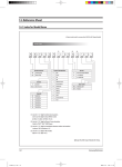
1
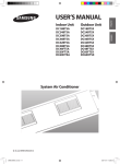
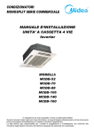
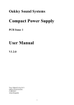
CH36BTAIM_E_23662 IB_E_23661 2005.12.19 8/17/05 3:33 PM AMPage 17 25 CH36BTA 9:35 Page INSTALLATION MANUAL CC18ETVX CC24ETVX CC36ETVX CC42GTVX CC48GTVX System Air Conditioner (Cooling Only) E A DB98-28263A(1) CH36BTX IM_E_23807 2005.12.16 11:28 AM Page 2 Safety Precautions The following safety precautions must be taken when using your air conditioner. WARNING INSTALLING THE UNIT Risk of electric shock. • Can cause injury or death. • Disconnect all remote electric power supplies before servicing, installing or cleaning. • This must be done by the manufacturer or its service agent or a similar qualified person in order to avoid a hazard. ◆ The unit should not be installed by the user. Ask the dealer or authorized company to install the units except room air conditioners for the U.S.A and Canada area. ◆ If the unit is installed improperly, water leakage, electric shock or fire may result. ◆ Mount with the lowest moving parts at least 2.5 m above the floor or grade level. (If applicable) ◆ The manufacturer does not assume responsibility for accidents or injury caused by an incorrectly installed air conditioner. If you are unsure about installation, contact an installation specialist. ◆ When installing the built-in type air conditioner, keep all electrical cables such as the power cable and the connection cord in pipe, ducts, cable channels e.t.c to protect them against liquids, outside impacts and so on. POWER SUPPLY LINE, FUSE OR CIRCUIT BREAKER ◆ If the power cord of this air conditioner is damaged, it must be replaced by the manufacturer, its service agent or similarly qualified persons in order to avoid a hazard. ◆ The unit must be plugged into an independent circuit if applicable or connect the power cable to the auxiliary circuit breaker. An all pole disconnection from the power supply must be incorporated in the fixed wiring with a contact opening of >3mm. ◆ Do not use an extension cord with this product. ◆ If the unit is equipped with a power supply cord and a plug, the plug must be accessible after installation. ◆ The air conditioner must be installed in accordance with national wiring regulations and safety regulations wherever applicable. E-2 CH36BTX IM_E_23807 2005.12.16 11:28 AM Page 3 Contents Preparation for outdoor unit installation ............................................................ Air conditioner and accessories ........................................................................ Deciding on where to install the outdoor unit ................................................... Outdoor unit installation .................................................................................... Connecting the cable ........................................................................................ Connecting the refrigerant pipe ........................................................................ Connecting up and removing air in the circuit .................................................. Cutting / Flaring the pipes ................................................................................... Performing leak tests ........................................................................................ Connecting the drain hose to the outdoor unit ................................................. Insulation ........................................................................................................... Using stop valve ............................................................................................... Adding refrigerant ............................................................................................. Checking correct grounding .............................................................................. Testing operations ............................................................................................. Optional parts List ............................................................................................. 5 5 6 9 10 15 16 17 18 18 18 19 20 22 23 24 E-3 CH36BTX IM_E_23807 2005.12.16 Type of outdoor unit 11:28 AM Page 4 A B C D CC18ETVX CC24ETVX CC36ETVX CC42GTVX CC48GTVX Design Model E-4 CH36BTX IM_E_23807 2005.12.16 11:28 AM Page 5 Preparation for outdoor unit installation Moving the Outdoor Unit by Wire Rope Wire rope Fasten the outdoor unit by two 8m or longer wire ropes as shown at the figure. To prevent from damage or scratches, insert a piece of cloth between the outdoor unit and rope, then move the unit. Plate protection cloth Air conditioner and accessories The following accessories are supplied with the air conditioner. The type and quantity may differ depending on the specifications. ◆CC36ETVX, CC42GTVX/CC48GTVX Flare Nuts 3/8" Cap Drain A Ring Terminal Rubber Bracket Wire Drain Plug Installation manual Rubber legs ◆ CC24ETVX Flare Nuts 1/4" Flare Nuts 5/8" Rubber legs Installation manual ◆ CC18ETVX Rubber legs Note Installation manual Refrigeration pipes and their insulating materials, power cables are not supplied. E-5 CH36BTX IM_E_23807 2005.12.16 11:28 AM Page 6 Deciding on where to install the outdoor unit Outdoor Unit ◆ The outdoor unit must not be placed on its side or upside down, as the compressor lubrication oil will run into the cooling circuit and seriously damage the unit. ◆ Choose a location that is dry and sunny, but not exposed to direct sunlight or strong winds. ◆ Do not block any passageways or thoroughfares. ◆ Choose a location where the noise of the air conditioner when running and the discharged air do not disturb any neighbours. ◆ Choose a position that enables the pipes and cables to be easily connected to the indoor unit. ◆ Install the outdoor unit on a flat, stable surface that can support its weight and does not generate any unnecessary noise and vibration. ◆ Position the outdoor unit so that the air flow is directed towards the open area. ◆ Maintain sufficient clearance around the outdoor unit, especially from a radio, computer, stereo system, etc. Indoor Unit Remote Controller 1m or m ore 1m or more Fuse ore 1.5m or m Fuse re mo e or r m r mo 1.5 o m 1.5 1.5m re or mo Outdoor Unit Stereo ◆ If the outdoor unit is installed at a height, ensure that its base is firmly fixed in position. ◆ Make sure that the water dripping from the drain hose runs away correctly and safely. CAUTION ◆ You have just purchased a system air conditioner and it has been installed by your installation specialist. ◆ This device must be installed according to the national electrical rules. E-6 CH36BTX IM_E_23807 2005.12.16 11:28 AM Page 7 Space Requirements for Outdoor Unit Unit : mm 2000 or more 600 or more When 3 sides of the outdoor unit are blocked by the wall 2000 or more 300 or more The upper part of the outdoor unit and the air outlet is towards the wall 300 or more 300 or more 500 or more When the air outlet is towards the wall 1500 or more 300 or more When the air outlet is opposite the wall 2000 or more 300 or more When installing 1 outdoor unit The upper part of the outdoor unit and the air outlet is opposite the wall When front and rear side of the outdoor unit is towards the wall E-7 CH36BTX IM_E_23807 2005.12.16 11:28 AM Page 8 Deciding on where to install the outdoor unit (Continued) When installing more than 1 outdoor unit 2000 or more Unit : mm 300 or more When the air outlet is towards the wall 300 or more 600 or more 600 or more 600 or more 600 or more 600 or more 2000 or more 300 or more When 3 sides of the outdoor unit are blocked by the wall When front and rear side of the outdoor unit is towards the wall 2000 or more 1000 or more 4000 or more 5000 or more When front and rear side of the outdoor unit is towards the wall E-8 200 or more CH36BTX IM_E_23807 2005.12.16 11:28 AM Page 9 Outdoor unit installation The outdoor unit must be installed on a rigid and stable base to avoid any increase in the noise level and vibration, particularly if the outdoor unit is to be installed in a location exposed to strong winds or at a height, the unit must be fixed to an appropriate support(wall or ground). Fix the outdoor unit with anchor bolts. Note The anchor bolt must be 20mm or higher from the base surface. Unit : mm Anchor bolt hole 543 340 364 3 10 319 343 283 Anchor bolt hole 660 788 880 Type A Type B Type C 427 375 3 40 880 364 320 645 403 Anchor bolt hole Anchor bolt hole 690 932 Type D CAUTION ◆ Make a drain outlet around the base for outdoor unit drainage. ◆ If the outdoor unit is installed on the roof, you have to check the ceiling strength and waterproof the unit. ◆ When installing the model CC48FT get rid of the cushion on the top of compressor. Outdoor Unit Support Outdoor ➔ Unit 20mm Anchor bolt ➔ Outdoor Unit Support Base Surface E-9 CH36BTX IM_E_23807 2005.12.16 11:28 AM Page 10 Connecting the cable Two electronic cables must be connected to the outdoor unit. ◆ The connection cord between indoor unit and outdoor unit. ◆ The power cable between outdoor unit and auxiliary circuit breaker. ◆ Specially for Russian and European market, before installation, the supply authority should be consulted to determine the supply system impedance to ensure compliance. Example of Air Conditioner System Power cable Communication cable When using ELB for 1 phase Outdoor Unit 1 Communication MCCB ELB Connection cord Earth Indoor Unit When using ELBs for 3 phase and 1 phase 1 3 ELB MCCB ELB MCCB Outdoor Unit Communication 1 Earth Indoor Unit ❋ If an outdoor unit is installed in a place in danger of an electric leak or submergence, you must install the ELB. E-10 CH36BTX IM_E_23807 2005.12.16 11:28 AM Page 11 Power Cable Specifications Type of outdoor unit Power Supply Single Phase 3 Phase Power Max/Min MCCB Supply (V) ELB Power Power Max/Min Cable Length Supply (V) MCCB ELB Power Cable Length A - - - - - - 220240V~ /50Hz ±10% Frame: 30A Trip:20A 20A 4.0mm 2, 2 Wires 20m or less B - - - - - - 220240V~ /50Hz ±10% Frame: 35A Trip:25A 25A 4.0mm 2, 2 Wires 20m or less 30A C - - - - - - 220240V~ /50Hz ±10% Frame: 35A Trip:30A D 3Φ/ 380415V~ /50Hz ±10% Frame: 30A Trip:20A 20A 4.0mm 2, 4 Wires 20m or less - - - Earth Cable 2 Ø1.6mm, 1 Wires 6.0mm 2, 2 Wires 20m or less - - - The power cable is not supplied with air conditioner. For power cable, use the grade H07RN-For H05RN-Fmaterials. Between Indoor and Outdoor Connection Cord Specifications Power Supply Power Supply CC18/24/36ETVX CC42/48GTVX Max/Min(V) Connection Wire ±10% 2.5mm2 2 wires 220-240V~/50Hz 3Φ/380-415V~ /50Hz Earth Cable Ø 1.6mm2 1 wire Outdoor Comp & Home server Fan Signal 2.5mm2 1 wires 0.75~ 1.25mm2 2 wires For connection cord, use the grade H07RN-F or H05RN-F materials. E-11 CH36BTX IM_E_23807 2005.12.16 11:28 AM Page 12 Connecting the cable (Continued) Wiring Diagram of Power Cable When using ELB for 1 phase Power Supply CC18ETVX Electrical component box MCCB ELB 3(C) MCCB Cable clamp 1 Phase Power Cable Connection Outdoor Comp & Cable Fan Signal Indoor Unit CC36ETVX CC24ETVX 3(C) 3(C) Cable clamp Cable clamp Connection Outdoor Comp Cable & Fan Signal 1 Phase Power Cable Connection Outdoor Comp Cable & Fan Signal 1 Phase Power Cable When using ELBs for 3 phase and 1 phase MCCB Single Phase ELB ELB MCCB MCCB 3 Phase 3 Wires Power Supply CC42/48GTVX Electrical component box 3(C) L1 L2 L3 N Cable clamp Indoor Unit E-12 Connection Cable Outdoor Comp & Fan Signal 3 Phase Power Cable CH36BTX IM_E_23807 2005.12.16 11:28 AM Page 13 CAUTION ◆ You should connect the power cable into the power cable terminal and fasten it with a clamp. ◆ The unbalanced power must be maintained within 2% of supply rating. - If the power is unbalanced greatly, it may shorten the life of the condenser. If the unbalanced power is exceeded over 4% of supply rating, the indoor unit is protected, stopped and the error mode indicates. ◆ To protect the product from water and possible shock, you should keep the power cable and the connection cord of the indoor and outdoor units in the iron pipe. ◆ Connect the power cable to the auxiliary circuit breaker. An all pole disconnection from the power supply must be incorporated in the fixed wiring(≥3mm). ◆ When connecting cables, make the cable pass through the cable tube as shown at the figure. Communication cable Connection cord Power cable Cable tube Gas refrigerant pipe Liquid refrigerant pipe ◆ Must keep the cable in a protection tube. ◆ Keep distances of 50mm or more between power cable and communication cable. E-13 CH36BTX IM_E_23807 2005.12.16 11:28 AM Page 14 Connecting the cable (Continued) Wiring Diagram of Connection Cord Indoor Unit (CC18ETVA) 1(L) 2(N) 3(C) 1(L) 2(N) Indoor Unit (CC24ETVA) 1(L) 2(N) F1 F2 V1 V2 F3 F4 3(C) L N CC18ETVX CC24ETVX Indoor Unit (CC36ETVA) 1(L) 2(N) 3(C) 3(C) F1 F2 V1 V2 F3 F4 N Indoor Unit (CC42/48GTVA) F1 F2 V1 V2 F3 F4 1(L) 2(N) 3(C) F1 F2 V1 V2 F3 F4 CC42/48GTVX CC36ETVX 1(L) 2(N) E-14 L 1(L) 2(N) 3(C) 3(C) L N 1(L) 2(N) 3(C) L1 L2 L3 N CH36BTX IM_E_23807 2005.12.16 11:28 AM Page 15 Connecting the refrigerant pipe Refrigerant Piping System L1 H L0 Pipe length or height Refrigerant piping system table Max. allowable length Actual pipe length L0 + H + L1 Allowable height length Actual pipe length H CC18/24ETVX 30m or less CC36ETVX CC42/48GTVX 50m or less CC18/24ETVX 15m or less CC36ETVX CC42/48GTVX 30m or less E-15 CH36BTX IM_E_23807 2005.12.16 11:28 AM Page 16 Connecting up and removing air in the circuit The air in the indoor unit and in the pipe must be purged. If air remains in the refrigeration pipes, it will affect the compressor, reduce to cooling capacity and could lead to a malfunction. Refrigerant for air purging is not charged in the outdoor unit. Use Vacuum Pump as shown at the figure. Outdoor unit Indoor unit A Gas pipe side C B Liquid pipe side D 1 Connect each assembly pipe to the appropriate valve on the outdoor unit and tighten the flare nut. 2 Referring to the illustration opposite, tighten the flare nut on section B first manually and then with a torque wrench, applying the following torque. Outer Diameter Torque (kgf•cm) 6.35 mm (1/4") 140~170 9.52 mm (3/8") 250~280 12.70 mm (1/2") 380~420 15.88 mm (5/8") 440~480 19.05 mm (3/4") 990~1210 22.23 mm (7/8") 990~1210 3 Connect the charging hose of low pressure side of manifold gauge to the packed valve having a service port as shown at the figure. 4 Open the valve of the low pressure side of manifold gauge counterclockwise. 5 Purge the air from the system using vacuum pump for about 10 minutes. ◆ Close the valve of the low pressure side of manifold gauge clockwise. ◆ Make sure that pressure gauge show -0.1MPa(-76cmHg) after about 10 minutes. Vacuum pump This procedure is very important in order to avoid gas leak. ◆ Turn off the vacuum pump. ◆ Remove the hose of the low pressure side of manifold gauge. B(liquid) 6 Set valve cork of both liquid side and gas side of packed valve to the open position. 7 Mount the valve stem nuts and the service port cap to the valve, and tighten them at the torque of 183kgf•cm with a torque wrench. 8 Check for gas leakage. ◆ At this time, especially check for gas leakage from the 3-way valve’s stem nuts(A port), and from the service port cap. Valve stem E-16 CH36BTX IM_E_23807 2005.12.16 11:28 AM Page 17 Cutting / Flaring the pipes 1 Make sure that you have the required tools available (pipe cutter, reamer, flaring tool and pipe holder). 2 If you wish to shorten the pipes, cut it with a pipe cutter, taking care to ensure that the cut edge remains at a 90° angle with the side of the pipe. Refer to the illustrations below for examples of edges cut correctly and incorrectly. O 90 Oblique Rough Burr 3 To prevent any gas from leaking out, remove all burrs at the cut edge of the pipe, using a reamer. 4 Slide a flare nut on to the pipe and modify the flare. Outer Diameter(D) 6.35 mm (1/4") 9.52 mm (3/8") 12.70 mm (1/2") 15.88 mm (5/8") 19.05 mm (3/4") 22.23 mm (7/8") 5 Check that the flaring is correct, referring to the illustrations below for examples of incorrect flaring. Inclined 6 Depth (A) 1.3mm 1.8mm 2.0mm 2.2mm 2.2mm 2.2mm Damaged Surface Cracked Uneven Thickness Align the pipes and tighten the flare nuts first manually and then with a torque wrench, applying the following torque. Outer Diameter 6.35 mm (1/4") 9.52 mm (3/8") 12.70 mm (1/2") 15.88 mm (5/8") 19.05 mm (3/4") 22.23 mm (7/8") Torque (kgf•cm) 140~170 250~280 380~420 440~480 990~1210 990~1210 CAUTION ◆ In case of welding the pipe, you must weld with nitrogen gas blowing. E-17 CH36BTX IM_E_23807 2005.12.16 11:28 AM Page 18 Performing leak tests Before completing the installation (insulation of the hose and piping), you must check that there are no gas leaks. B To check for gas leaks on the... Then, using a leak detector, check the... Outdoor unit Valves on sections A and B. A Connecting the drain hose to the outdoor unit When using the air conditioner in the heating mode, ice may accumulate. During de - icing, the condensed water must be drained off safely. Consequently, you must install a drain hose on the outdoor unit, following the instructions below. 1 Make space more than 50mm between the bottom of the outdoor unit and the ground for installation of the drain hose, as shown in figure. 2 Insert the drain plug into the hole on the underside of the outdoor unit. 3 Connect the drain hose to the drain plug. 4 Ensure that the drained water runs off correctly and safely. 50mm min. Insulation Once you have checked that there are no leaks in the system, you can insulate the piping and hose. 1 No gap To avoid condensation problems, place an insulator around each refrigerant pipe. Note ◆ When insulate the pipe, be sure to overlap the insulation. ◆ You have to use more than 120°C insulation(T13.0 or thicker Acrylonitrile Butadien Rubber) for the gas refrigerant pipe. NBR(T13.0 or thicker) E-18 CH36BTX IM_E_23807 2005.12.16 11:28 AM Page 19 Using stop valve To Open the Stop Valve 1 Open the cap and turn the stop valve counterclockwise by using a hexagonal wrench. 2 Turn it until the axis is stopped. Note ◆ Do not apply excessive force to the stop valve and always use special instruments. Otherwise, the stopping box can be damaged and the back sheet can leaks. ◆ If the watertight sheet leaks, turn the axis back by half, tighten the stopping box, then check the leakage again. If there is no leakage any more, tighten the axis entirely. 3 Cap Service port Axis Sealing point Tighten the cap securely. To Close the Stop Valve 1 Remove the cap. 2 Turn the stop valve clockwise by using a hexagonal wrench. 3 Tighten the axis until the valve reached the sealing point. 4 Tighten the cap securely. CAUTION ◆ When you use the service port, always use a charging hose, too. ◆ Check the leakage of refrigerant gas after tightening the cap. ◆ Must use a spanner and wrench when you open/tighten the stop valve. E-19 CH36BTX IM_E_23807 2005.12.16 11:28 AM Page 20 Adding refrigerant The outdoor unit is loaded with sufficient refrigerant for the standard piping. Thus, refrigerant must be added if the piping is lengthened. This operation can only be performed by a qualified refrigeration specialist. For quantity of adding refrigerant, refer to page 21. 1 Check that the stop valve is closed entirely. 2 Charge the refrigerant through the service port of liquid stop valve. Note ◆ Do not charge the refrigerant through the gas side service port. Note ◆ If necessary, refer to the pressure table classified by outdoor temperature. Outdoor unit Liquid side stop valve(service port) Gas side stop valve(service port) Ref. Indoor unit Balance E-20 Vacuum pump 1 CH36BTX IM_E_23807 2005.12.16 11:28 AM Page 21 How to Calculate the Quantity of Adding Refrigerant If you have used more than 5m, add “Q” of refrigerant for extra meter. (For maximum piping length and height, refer to page 15) The quantity of additional refrigerant is variable according to the installation situation. Thus, make sure the outdoor unit situation before adding refrigerant. This operation can only be performed by a qualified refrigeration specialist. Model “Q” (R22) CC18ETVX 20g/m CC24ETVX 35 g/m CC36ETVX 30g/m CC42GTVX 35g/m CC48GTVX 30g/m Model Additional charging amount Piping length 5.0m Piping length 7.5m Indoor Unit Outdoor Unit CC18ETVA CC18ETVX - 50g CC24ETVA CC24ETVX - 87.5g CC36ETVA CC36ETVX - 75g CC42GTVA CC42GTVX - 87.5g CC48GTVX - 75g CC48GTVA E-21 CH36BTX IM_E_23807 2005.12.16 11:28 AM Page 22 Checking correct grounding If the power distribution circuit does not have an earth or the ground does not comply with specifications, an grounding electrode must be installed. The corresponding accessories are not supplied with the air conditioner. Carbon plastic Steel core PVC-insulated green/ yellow wire 1 Select an grounding electrode that complies with the specifications given in the illustration. 2 Determine a suitable location for the grounding electrode: ◆ In damp hard soil rather than loose sandy or gravel soil that has a higher grounding resistance ◆ Away from underground structures or facilities, such as gas pipes, water pipes, telephone lines and underground cables ◆ At least two metres away from a lightening conductor grounding electrode and its cable Terminal M4 To grounding screw 50cm Note 30cm 3 Finish wrapping insulating tape around the rest of the pipes leading to the outdoor unit. 4 Install a green/yellow coloured grounding wire: ◆ If the grounding wire is too short, connect an extension lead, in a mechanical way and wrapping it with insulating tape (do not bury the connection) ◆ Secure the grounding wire in position with staples Note E-22 ◆ The grounding wire for the telephone line cannot be used to ground the air conditioner. ◆ If the grounding electrode is installed in an area of heavy traffic, its wire must be connected securely. 5 Carefully check the installation, by measuring the grounding resistance with a ground resistance tester. If the resistance is above required level, drive the electrode deeper into the ground or increase the number of grounding electrodes. 6 Connect the grounding wire to the electrical component box inside of the outdoor unit. CH36BTX IM_E_23807 2005.12.16 11:28 AM Page 25 Testing operations 1 Check the power supply between the outdoor unit and the auxiliary circuit breaker. Single phase power supply: L, N Three phase power supply: L1, L2, L3, N 2 Check the indoor unit. 2-1 Check that you have connected the power and communication cables correctly. (If the power cable and communication cables one mixed up or connected incorrectly, the PCB will be damaged.) 2-2 Check the thermistor sensor, drain pump/hose, and display are connected correctly. 3 Connect the outdoor unit to your computer where the provided software is installed, then supply power to the outdoor unit. E-23 CH36BTX IM_E_23807 2005.12.16 11:29 AM Page 28 Optional parts list Wired Remote Controller Accessories Wired remote controller Cable-tie Cable clamp 1 2 5 7 1 Wire joint Owner’s instructions Installation manual 1 1 1 Communication cable of the wired remote controller 1 M4x16 tapped Indoor unit power screw drawing cable Centralized Controller Accessories Centralized controller Cable-tie Cable clamp M4x16 tapped screw Owner’s instructions Installation manual 1 2 5 7 1 1 Function Controller Accessories Function controller Cable-tie Cable clamp M4x16 tapped screw Owner’s instructions Installation manual 1 2 6 7 1 1 Owner’s instructions Installation manual 1 1 Wireless Remote Controller Accessories E-24 Wireless remote controller Battery 1 2 Remote STS 2S-2x10 control holder tapped screw 1 2 CH36BTX IM_E_23807 2005.12.16 11:29 AM Page 30 Printed in Korea