1
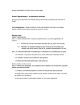
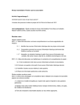
High Quality, Ultra-Thin,
17th Edition Compliant
Heating Mat
Fitting Guide – version 2
Call 01444 247020 for Technical Support
Underfloor Heating – made easy...
Please ensure you read this guide
completely before commencing
installation of the underfloor
heating. If you are unsure of any
aspect of the installation please
call Heat Mat’s Technical Support
helpline on 01444 247020.
Contents
Do’s and Don’ts
Technical information
Basic wiring diagram and warning label
System and testing information
Installation instructions
Electrical information
Warranty information
3
4
5
6
7
10
11
Before commencing your installation, please check
that you have the correct heater or combination of
heaters for your chosen area. (see page 6 for details)
Heat Mat Limited accept no liability, either express or implied, for any consequential losses incurred as a
result of a Heat Mat system installation that does not conform to the following installation instructions.
2
Please visit our website www.heatmat.co.uk for further information.
Do’s and Don’ts
• Do thoroughly read this guide
before commencing installation
• Don’t cut, shorten, strain or cross
the heating cables.
• Do ensure that all heating wire (including
joints) is fitted beneath the floor covering
• Don’t bend the joint between
the element and cold tail
• Do use a multi-meter to test the mat,
before, during and after covering
(see page 4)
• Don’t supply power to the heater until
the mat has been fully encased and the
wet trade has been allowed to fully dry out
• Do connect multiple mats in parallel
• Don’t lay cables closer than 3cm
to each other or conductive parts
• Do consider thermally insulating
your sub-floor before installing
the underfloor heating system
• Do use a Heat Mat thermostat
to control your system
• Do ensure that all electrical works conform
to Part ‘P’ of the Building Regulations and
current IEE Wiring Regulations
• Do ensure the system is protected
by a suitable RCD device (30mA)
• Do ensure that the cable is more
than 30mm away from conductive
parts such as water pipes
• Do remove cable from it’s mesh
to fit awkward areas
• Do ensure that all heating cable and
connections are covered with tile
adhesive or levelling compound
• Don’t install the system if the ambient
temperature is below 5ºC as the cables
on the mats can become less flexible
• Don’t install the mats in
walls or ceilings
• Don’t install the floor sensor close to other
heat sources such as hot water pipes
• Don’t begin covering with tile adhesive
or levelling compound until the mat
is in place and has been tested with
a multi-meter (see page 4)
• Don’t leave any sections of the heating
cable or connections in the open air or
beneath fixtures and fittings when
installation is completed
• Don’t use the heating system to
help to dry out the wet trade
• Do log on to www.heatmat.co.uk to
ensure that you are using the most
recent instructions
Tel: 01444 247020
3
Technical
specification
200 W/m2 Technical Specification
Size in m2
Length in Metres
2
1.0 m
1.6 m2
2.0 m2
2.6 m2
2.8 m2
3.5 m2
4.2 m2
5.4 m2
6.0 m2
6.7 m2
7.5 m2
8.9 m2
9.9 m2
2.0 m
3.2 m
4.0 m
5.2 m
5.6 m
7.0 m
8.4 m
10.8 m
12.0 m
13.4 m
15.0 m
17.8 m
19.7 m
Width in Metres
Wattage
0.5 m
0.5 m
0.5 m
0.5 m
0.5 m
0.5 m
0.5 m
0.5 m
0.5 m
0.5 m
0.5 m
0.5 m
0.5 m
Resistance
208 W
310 W
405 W
512 W
576 W
719 W
854 W
1083 W
1196 W
1353 W
1504 W
1769 W
1973 W
277
186
142
113
100
80
67
53
48
43
38
33
29
ΩΩ
ΩΩ
ΩΩ
ΩΩ
ΩΩ
ΩΩ
ΩΩ
ΩΩ
ΩΩ
ΩΩ
ΩΩ
ΩΩ
ΩΩ
150/160 W/m2 Technical Specification
Size in m2
Length in Metres
1.1 m2
1.5 m2
2.0 m2
2.3 m2
2.8 m2
3.1 m2
3.7 m2
4.4 m2
5.2 m2
6.2 m2
6.8 m2
7.7 m2
8.7 m2
10.4 m2
2.2 m
3.0 m
4.0 m
4.6 m
5.6 m
6.2 m
7.4 m
8.8 m
10.4 m
12.4 m
13.6 m
15.4 m
17.4 m
20.8 m
Technical Data:
General Construction:
Voltage:
Maximum Load:
Maximum Cable Temperature:
Approvals:
Wire Thickness:
Cable Flexibility:
Power Range:
Approved in accordance with:
Width in Metres
Wattage at 230Vac
0.5 m
0.5 m
0.5 m
0.5 m
0.5 m
0.5 m
0.5 m
0.5 m
0.5 m
0.5 m
0.5 m
0.5 m
0.5 m
0.5 m
168 W
221 W
318 W
340 W
401 W
454 W
546 W
644 W
781 W
919 W
1013 W
1154 W
1300 W
1543 W
315
240
166
155
132
116
97
82
68
58
52
43
40
34
ΩΩ
ΩΩ
ΩΩ
ΩΩ
ΩΩ
ΩΩ
ΩΩ
ΩΩ
ΩΩ
ΩΩ
ΩΩ
ΩΩ
ΩΩ
ΩΩ
Construction:
Dual conductor wire with earth
240 Vac – 50Hz
15 W/m
90 ºC
CE Marked, VDE and BEAB
system approved
2.7mm to 3.2mm depending
on Ohm Value
Minimum allowable cable radius
is 18mm
168W to 1973W
EN 60335-1:1998,
EN60335-2-17:1999, IEC 60730
Thermal Conductor:
Outer Insulation:
Reinforcement Materials:
IP Rating:
Reinforcement Mesh:
Fixing Materials:
2 x resistance wire insulated with
fluoropolymer (FEP 7Y) tested to 200ºC
PVC (Y) tested to 90ºC
Fibreglass strands
IPX7
Fibreglass mesh
Supplied with rows
of double-sided tape
150 W/m2 Mat Outputs are calculated at 230Vac
4
Resistance
Please visit our website www.heatmat.co.uk for further information.
Basic wiring diagram
and warning label
Typical Wiring System
• All electrical works must be carried out by a certified electrician.
• A suitable RCD protection must be incorporated in this system.
• If the ampage of the thermostat is exceeded by your chosen system,
a contactor or similar device will be required. All thermostats used
must be of a two-pole design with a minimum opening between the
contacts of 3mm. For full BEAB system approval you must use a
suitable Heat Mat BEAB approved thermostat.
• The heating cables must not be cut or cross each other or
other wiring.
• The cold tail joint must be kept straight and located beneath
the final floor covering and must be thoroughly encased in
tile adhesive or levelling compound.
• Please consult your electrician to discuss your individual
requirements.
Switched Fused Spur
Thermostat
Power Supply
through an RCD
18oC
1.3m above floor
Floor
Heating Element to cold tail joint
Floor Sensor
Please see the back page
of this fitting guide for the
required information label
for the distribution board.
It is a legal requirement that
this label is completed and
the required information is
displayed near the relevant
distribution board.
Tel: 01444 247020
5
Guide to choosing
the correct system
As a guide to confirming the wattage per
square metre (W/m2) that you require,
please use the following advice in
conjunction with the tables on page 4.
150W/m2 Table – Standard rooms:
When using any suitable floor covering including tiles,
carpet, vinyl or wood. These mats can be laid straight onto
wooden or *insulated concrete bases. They can provide
primary heating in well insulated areas and secondary
heating in other circumstances. (Please note a levelling
compound will be required for use with any floor covering
other than tiles.)
200W/m2 Table – High heat loss rooms:
When using beneath tiles on insulated concrete bases and
when primary heating is a priority. The 200W/m2 system
is capable of providing primary heating in almost any
situation providing the sub-floor is reasonably *insulated.
Speak to your electrician or builder to confirm that the
system output meets your individual requirements.
Calculating coverage:
Although 100% coverage is achievable, a border of 2-4cm
is recommended around the perimeter of the room as the
heating cables should not touch the walls, kickboards etc.
In normal circumstances we would recommend deducting
between 5 and 10% from the total free floor space that
you wish to heat, to give you the square metres of heating
mat that you should install. For areas above 8m2 we
would recommend only deducting 5%.
For instance: You have a 15.0m2 kitchen that is going
to have a tiled floor and contains units that will take
up 2.8m2 of the floor area, which therefore should
not be heated. You wish to use a 200W/sqm heating
mat system. The calculation you should use is as follows:
15.0m2 – 2.8m2 = 12.2m2 then 12.2m2 – 5% = 11.59m2
Refering to the table on page 4, the best combination
of heating mats would be:
1 x 9.9m2 200W mat and 1 x 1.6m2 200W mat.
We would recommend planning your
installation before starting to lay your system,
and also that you photograph your system
layout before tiling for future reference.
* Insulation within the floor base minimises downward heat loss allowing your underfloor heating to run more efficiently.
Insulation laid directly beneath the underfloor heating will provide the largest benefit, and the further down in the floor build the insulation is
(such as beneath a screed) the less benefit it will offer. Systems laid onto very badly insulated floor bases may not meet your expectations.
Testing your Heating Mat
with a multi-meter
Test your heating mat with a multi-meter before
unwrapping to confirm you have received it in
working order.
The black coldtail is double insulated and carries
an earth screen (silver braid), live and neutral wires.
Exposing the ends of these wires will allow the continuity
tests to be carried out with a functional multi-meter.
This test should also be done before, during and after tiling.
6
At no point should any cable be connected to a power
supply to test it.
Tests
• Live to neutral = ohms value as in table on page 4
• Live to earth and neutral to earth = both infinity.
If your tests do not conform to the expected results
please contact Heat Mat’s Technical Support Team.
Please visit our website www.heatmat.co.uk for further information.
Installation
instructions
fig.1
Floor preparation
Ensure the sub-floor is solid, level and dust free.
Wooden floors can be reinforced using 18mm
WPB plyboard, 10mm Marmox Insulation boards or
suitable Tilebacker boards. We would also recommend
that the entire floor base is of the same construction
to ensure the system performs evenly. If the floor
construction is not uniform you should use Marmox
boards or similar to provide a uniform base.
The sub-floor should be insulated to current building
regulations, however, if you are unsure how well
insulated your sub-floor is, Heat Mat can supply
6, 10 or 20mm Marmox Insulation boards. Insulation
improves the performance and efficiency of your system,
therefore reducing running costs. If there is little or no
insulation within the sub-floor we would recommend
using a suitable layer of insulation.
If installing Marmox boards, these should be secured
with flexible tile adhesive onto concrete sub-floors,
or with galvanised screws and washers onto timber
bases. Reinforcement tape should be used across
the joins. See www.heatmat.co.uk for further details.
If you do not have the build height required for Marmox
boards Heat Mat supply i-primer thermal primer which,
although less effective than Marmox boards, can reduce
downward heat loss by up to 20%. The thermal primer
is acrylic based and should be compatible with all
flexible tile adhesives. If in doubt please confirm
compatibility with the tile adhesive manufacturer.
fig.2
Installing the Ultra-Thin
Heating Mat System
Test each mat with a multi-meter before unpacking to
ensure you have received your product in full working
order. See the bottom of page 6 for testing instructions.
Draw a plan of how you intend to fit your mat/s.
Roll out your first mat onto your floor mesh side up. (fig.2)
Cut across the fibreglass mesh when you reach an
obstruction, carefully avoiding the heating cable, and
you can then flip the mat around and start laying it in
the opposite direction (figs.3 and 4). In awkward areas
the heating cable can be removed from the fibreglass
mesh and laid loosely to ensure the heating system
fits your room. When doing this, try to keep the spacing
between the cables similar to that on your mat to maintain
an even output across the floor area and never let the
cables touch or cross. The cables should be secured to
the floor with double sided tape.
Once in position, remove the backing from the adhesive
tape attached to the underside of your mat/s and secure
to your base (fig 5). Any loose cable or mesh can be
secured by using a hot glue gun or masking tape.
The cables should never be less than 30mm apart
whether they are on the heating mat or laid loosely.
If you find that you have to lay the cable separated from
the mat in rows less than 30mm apart to fit your room,
STOP, as the matting is too big for your area. The heating
cable can not be cut to shorten itself without destroying it.
If using our thermal primer to insulate your floor
you should ensure the room is well ventilated during
Tel: 01444 247020
7
Installation
instructions
fig.3
application and drying. The thermal primer can reduce
heat loss through the base by up to 20%. (fig.1)
Ensure that both sections of each mat with orange
warning labels are kept straight and laid flat to the
floor beneath your final floor covering. These will have
to be chased into the sub-floor to ensure they rest at the
same height as the top of the heating cable. These must
not be covered with tape, but do have to be fully encased
in tile adhesive. (fig.6)
fig.4
Multiple mats can be installed in one room but must
be connected in parallel (they do not join together).
Up to 2 heating mats can be wired directly into the
back of the thermostat. More than two mats will require
a connection box. If your chosen system exceeds 16amp
(approximately 3,600 watts), additional thermostats can
be used or your electrician can install a contactor or
similar device to allow the heating system to operate
safely through a single thermostat.
Position the floor sensor (contained inside the thermostat
box), halfway between two runs of the heating elements
(fig.7). The floor sensor should not cross the heating cable
and should be placed approx. 40cm into the heated floor
space. The floor sensor at the end of the cable should
also be chased into the sub-floor so it lies level with
the top of the heating cables. The sensor cable can be
extended if required up to 50m using a twin sheathed
high temperature PVC cable and the connection between
the two wires must be waterproof and fully insulated.
Ideally, the floor sensor should be placed into a length
of suitable close ended conduit (12-14mm diameter)
so that it can be easily replaced if required.
Test the heating system with a multi-meter again prior
to covering. We would recommend taking a photograph
of the layout of your system and the positioning of the
floor sensor at this stage for future reference.
The floor sensor should not be fitted in areas affected
by other heat sources, such as hot water pipes and
radiators, or in an area that will be covered at a later
date with items such as rugs or flat bottomed furniture,
as this will prevent the system from operating correctly.
Wear soft soled shoes and cover the system with
carpet/cardboard to protect it where you are working
during installation. Do not allow any unnecessary traffic
across the cabled area until the floor covering is
completed. Do not stack or cut tiles across the cabled
area and take care to avoid dropping sharp objects or
tiles onto the cables as this can crush or cut into them.
If using one of Heat Mat’s infra-red wall mounted floor
sensors you are not required to include an additional
floor sensor within the floor construction.
8
If covering is not going to happen straight away, protect
the heater/s by covering with cardboard or carpet and
restrict any traffic above the cable to a minimum. After
removing the protective covering before laying the final
floor covering you should check the continuity of the
cable before proceeding.
Covering the Heating Mat System
Please visit our website www.heatmat.co.uk for further information.
Installation
instructions
fig.5
fig.6
Check the resistance and continuity of the cable with a
multi-meter regularly during installation. If the resistance
changes, or the cable goes to open circuit, the cable has
been damaged. In this case, please contact Heat Mat’s
Technical Support line on 01444 247020. Even a small
nick in or scratch to the outer insulation can lead to
system failure when powered up over a period of time.
Heat Mat can supply Mira Thermoplan levelling compound
to incapsulate the heating cable (mosaic tiles, carpets,
vinyl and wood coverings require a layer 10-12mm from
base level). Using a suitable flexible levelling compound
reduces the risk of damage to the cables caused by using
tile trowels and should a tile need to be replaced in the
future, the heating cable is less likely to be damaged.
Air pockets around the cables are also less likely with
this method of installation. See www.heatmat.co.uk
for further details on Mira installation.
Whether using flexible levelling compound or tile adhesive
to cover your cable, you should avoid leaving air pockets
around the heating cable. In no circumstances must tiles
be laid with dabs of adhesive, they must always be fully
bedded in.
If using tile adhesive and grout to complete your
installation they must be suitable for underfloor heating,
the main requirement being that they are ‘flexible’
adhesives and grouts. Please refer to the manufacturers
instructions to confirm suitability.
If using flexible tile adhesive, a plastic notched trowel
should be used to push the adhesive along the cable rather
than against it. Care should be exercised to prevent damage
fig.7
to or dislodging of the heating cables. Ideally, lay carpet
or cardboard on top of the exposed cable and use this
as a crawl board to avoid damaging the system.
Although the cable is reinforced, it is ideal if the trowel
does not make contact with the cable itself.
If a tile needs to be moved after placement this must
be done carefully to avoid damaging the heating cable.
The floor should be grouted with a flexible grout, and
particular care should be taken not to damage the heating
system when cleaning out any grout lines. The underfloor
heating must never be used to ‘dry out’ the tile adhesive.
The system must not be turned on until the adhesive,
grout and/or levelling compound is completely dry.
This would normally take at least seven days,
but please refer to the appropriate manufacturers
instructions for confirmation.
Once the floor covering is laid, test the resistance
and continuity of the heating mats individually to
confirm they are undamaged.
Tel: 01444 247020
9
Installation
instructions
Electrical connections
Wiring can now be completed but no power should be
applied to the system until the adhesive, grout and/or
levelling compound is completely dry.
All work must comply with current IEE wiring regulations
and installations must comply with Part ‘P’ of the Building
Regulations. Consult your Local Authority Building Control
department regarding their requirements for certification
or check with an electrician qualified to issue Part ‘P’
certification regarding your individual installation.
The heating mat/s have to be wired into a thermostat
with floor temperature limitation. Please see the separate
instructions in your Heat Mat thermostat box.
Run the coldtail connection and floor sensor cable in
separate plastic conduit or trunking from your heated
floor to the thermostat position.
Up to 2 heating mats can be wired straight into the
thermostat. A connection box will be required if installing
3 or more heating mats. Ensure that multiple mats are
wired in parallel, not in series.
The mains power supply must be protected by a suitable
RCD (30mA and up to 4.8kW).
The thermostat should be connected to the power supply
via a suitably rated fused spur or circuit breaker.
Heat Mat’s thermostats are rated 16 Amp and if the total
loading from a combination of heating mats exceeds this,
the system will require multiple thermostats or we would
recommend the installation of a suitable rated contactor
which would allow the heating system to be run through
a single thermostat for ease of control.
Heat Mat’s thermostats are IP21 rated, which means
that they can be installed within a wet area in Zone 3
if it is available.
If the thermostat is placed outside the room to be
heated, or inside a cupboard, the thermostat will have
to be reprogrammed (when first switched on) to only
monitor the floor sensor that has been placed into the
heated floor space.
10
Remember:
If you are unsure how to
proceed at any stage of the
installation process, please
contact Heat Mat Technical
Support on 01444 247020
for guidance.
Living with your Underfloor
Heating System
To ensure that your system works to its full capacity
for the lifetime of the flooring, please ensure that
thermal blocking is avoided above the heating system.
Thermal blocking occurs when the heat produced by the
system warms the floor surface but is then trapped and
has no way of escaping from the surface of the floor.
This can cause the system to overheat in the thermally
blocked area and, in extreme cases, affect the integrity
of the floor covering and heating system.
Heat Mat’s thermostats are IP21 rated, and the heating
mats are IPX7 rated, which means systems can be
installed in bathrooms and other ‘wet areas’ and if a
suitable zone is available the thermostat can also be
placed in the bathroom.
Thermal blocking is not usually a problem within floors
where the system has been covered with levelling
compound or tile adhesive and tiles, as these coverings
are efficient transmitters of heat themselves and
will spread the heat around any thermal block.
Thermal blocking has a greater chance of occurring
in situations with a carpeted, wooden or laminate
floor finish that do not utilise a levelling compound
as these coverings do not transmit heat as effectively.
Please visit our website www.heatmat.co.uk for further information.
Heat Mat
Lifetime Warranty
Congratulations on your purchase of a
Heat Mat electric underfloor heating system.
The ultra-thin heating mat has been manufactured
and supplied in the European Union by Heat-Com
a/s/Heat Mat Limited, and the following Warranty is
supplied in accordance with the general product liability
rules, as stated in Directive 85/374/CEE, and all relevant
national laws. You are provided with a fifteen year
warranty on the ultra-thin heating mat for eventual
defects in material. Details and evidence of defects has
to be presented to Heat-Com, Heat Mat or an authorised
UK or Ireland distributor for approval.
When your warranty is invoked, your damaged product
will either be repaired or replaced free of charge to yourself.
Your warranty does not cover the following:
• Any faults caused by misuse.
• A system which has not been installed in accordance
with the manufacturer’s guidelines.
• Any other subsequential or consequential damages.
• Any system that had not been paid for in full.
Heat-Com a/s/Heat Mat Limited are covered by an
international insurance covering warranty payments.
Heat Mat Limited,
Ashwyn Business Centre,
Marchants Way,
Burgess Hill. RH15 8QY
T 01444 247020
F 01444 247121
www.heatmat.co.uk
In addition to the above warranty, Heat Mat offer a
lifetime extension to the above warranty on your ultrathin heating mat. To be covered by this extra warranty
in addition to the above stipulations you must also:
• Register your product at
www.heatmat.co.uk/warrantyregistration
within 90 days of purchase.
• Be able to provide your proof of purchase of the
system, a normal retail invoice/receipt is sufficient
for this purpose.
• Ensure the system has been installed in accordance
with Heat Mat’s installation guidelines and it must be
protected by a suitable RCD.
• Ensure that all installation work is compliant with current
IEE wiring regulations and installations must comply with
Part ‘P’ of the Building Regulations. You should retain
your Part ‘P’ certificate as proof of this.
If the above stipulations have been followed, Heat Mat
will provide a lifetime warranty once the original fifteen
year warranty expires for the ultra-thin heating mat.
This warranty runs for the life of the floor covering above
the original installation. This warranty covers manufacturing
defects in the ultra-thin heating mat supplied. Details and
evidence of defects has to be presented to Heat Mat or an
authorised UK or Ireland distributor for approval. When your
warranty is invoked, your damaged product will either be
repaired or replaced free of charge to yourself.
The repair or replacement of your system is the only remedy
available to you under these warranties. None of the above
warranties affect your statutory rights. Heat-Com a/s and
Heat Mat Limited will in no event be liable for consequential
losses or secondary charges including but not restricted to
the cost of replacing or repairing floor coverings, any costs
associated with utility expenses or running costs,
professional fees relating to trades peoples’ subsequent
work or any other damage caused to material items.
Tel: 01444 247020
11
Please complete and display at your distribution board.
Warning
This building is fitted with Heat Mat 100% earth shielded electric underfloor heating
utilising a 240Vac supply.
Do NOT pierce the floors above the system with nails, screws or other fasteners.
(see installer diagram for heater positioning)
Do NOT expose the floor to thermal blocking or attempt to reduce the size of
the heated floor area.
(check suitability of floor covering with manufacturer & that furniture
has 10mm (min) air void beneath it.)
In the event of flooding or when carrying out any repairs or alterations, disconnect the
underfloor Heating and contact your electrician or Heat Mat for advice
Details of Installation:
Electricians Name:
Signature:
Company Name:
& Address:
Date:
Room with heating installed:
Total Wattage of system:
Please list the product code and test results of each element
after installation (compare to installation guide for rated resistance)
Product Code
Resistance Rating
Insulation Test Passed
Heat Mat Ltd - Tel No: 01444 247020
see www.heatmat.co.uk for more underfloor heating solutions
This installation guide should be left with the thermostat user manual and the installer's
heater layout & wiring diagrams to meet IEE Wiring regulations (17th Edition – section 753).
These items should be permanently fixed near the relevant distribution board.
Heat Mat Limited, Ashwyn Business Centre,
Marchants Way, Burgess Hill. RH15 8QY
www.heatmat.co.uk
Reproduction of part or all of the contents
of this fitting guide in any form is prohibited
other than with the express written
permission of Heat Mat Limited.