1
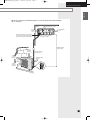
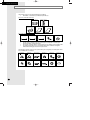
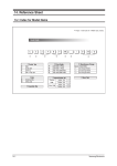
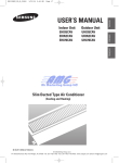
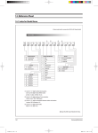
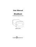
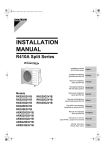
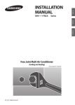
4:26 PM
Page 17
INSTALLATION
MANUAL
Outdoor Unit
AQB09JJWC
AQB12JJWC
UQB09JJWC
UQB12JJWC
FRANÇAIS
Indoor Unit
ENGLISH
2006.4.17
ESPAÑOL
AQB09JJ6WC_IM_E_25853
Split-type Air Conditioner
(Cooling and Heating)
E S F DB98-25853A(2)
AQB09JJ6WC_IM_E_25863
3/24/06 10:18 PM
Page 2
Safety Precautions
You should take the following safety precautions when using your air conditioner.
WARNING
INSTALLING THE
AIR CONDITIONER
• If you don’t follow the safety precautions, you may get the risk of an
electric shock, injury or death. • The manufacturer or qualified service
personnel must install this air conditioner. • Unplug the electric power
before repairing, installing or cleaning.
◆ Users should not install the air conditioner by themselves.
Ask the dealer or authorized company to install the air conditioner
except the window-type air conditioner in U.S.A and Canada.
◆ If you don’t install the air conditioner properly, it may cause a fire,
a water leakage or an electric shock.
◆ Install the indoor unit higher than 8.2ft(2.5m) from the floor to avoid the
injury caused by the operation of the fan.
(except the window-type air conditioner)
◆ The manufacturer is not responsible for the accidents or injury caused
by an incorrect installation.
◆ When installing the built-in type air conditioner, keep all electric cables
such as the power cable and the connection cord in pipes, ducts, or
cable channels to protect them from the danger of impact or any other
incidents.
POWER SUPPLY AND
CIRCUIT BREAKER
◆ If the power cord of the air conditioner is damaged, it must be replaced by
the manufacturer or a qualified person in order to avoid a hazard.
◆ The air conditioner must be plugged into an independent circuit if
applicable or connect the power cable to the auxiliary circuit breaker.
An all pole disconnection from the power supply must be
incorporated in the fixed wiring with a contact opening of >0.118 inch(3mm).
◆ Do not extend an electric cord to the air conditioner.
◆ You must install the air conditioner according to the national wiring
regulations and safety regulations.
E-2
3/24/06 10:18 PM
Page 3
ENGLISH
AQB09JJ6WC_IM_E_25863
Contents
◆ PREPARING THE INSTALLATION
■ Deciding the Installation Place . . . . . . . . . . . . . . . . . . . . . . . . . . . . . . . . 4
■ Accessories . . . . . . . . . . . . . . . . . . . . . . . . . . . . . . . . . . . . . . . . . . . . . . . 6
◆ INSTALLING THE AIR CONDITIONER
■ Fixing the Installation Plate . . . . . . . . . . . . . . . . . . . . . . . . . . . . . . . . . . . 7
■ Purging the Indoor Unit . . . . . . . . . . . . . . . . . . . . . . . . . . . . . . . . . . . . . 7
■ Connecting the Assembly Cable . . . . . . . . . . . . . . . . . . . . . . . . . . . . . . . 8
■ Installing and Connecting the Drain Hose of the Indoor Unit . . . . . . . . . . . . . . . 9
■ Installing and Connecting the Drain Hose of the Outdoor Unit . . . . . . . . . . . . . . 9
■ Installing and Connecting the Assembly Pipe of the Indoor Unit . . . . . . . . . . . 10
■ Cutting or Extending the Pipe . . . . . . . . . . . . . . . . . . . . . . . . . . . . . . . . 11
◆ COMPLETING THE INSTALLATION
■ Purging the Connected Pipes . . . . . . . . . . . . . . . . . . . . . . . . . . . . . . . . 12
■ Performing the Gas Leak Tests . . . . . . . . . . . . . . . . . . . . . . . . . . . . . . . 13
■ Fixing the Indoor Unit in Place . . . . . . . . . . . . . . . . . . . . . . . . . . . . . . . 13
■ Fixing the Outdoor Unit in Place . . . . . . . . . . . . . . . . . . . . . . . . . . . . . . 14
■ Checking and Testing Operations . . . . . . . . . . . . . . . . . . . . . . . . . . . . . 14
■ Providing Information for User . . . . . . . . . . . . . . . . . . . . . . . . . . . . . . . 15
E-3
AQB09JJ6WC_IM_E_25863
3/24/06 10:18 PM
Page 4
PREPARING THE INSTALLATION
Deciding the Installation Place
You should observe the following restrictions when you decide the installation place.
General
Do NOT install the air conditioner under the following conditions;
◆ Combustible gases
◆ Saline air
◆ Machine oil
◆ Sulphide gas
◆ Special environmental conditions
If you have no alternative place to install it, first consult your dealer or a qualified person.
Indoor Unit
◆ There must be no obstacles near the air inlet and outlet.
◆ Install the indoor unit on a surface that can support its weight.
◆ Choose a place where you can easily connect the pipes and cables to the outdoor unit.
The recommended length of the pipes and cables is 24.6ft(7.5m). The maximum length is 49ft(15m).
◆ Leave sufficient space below the indoor unit to remove the filters easily.
◆ Maintain sufficient space around the indoor unit as seen in the picture on page 5.
◆ Make sure that the water dripping from the drain hose runs off correctly and safely.
◆ Install the indoor unit higher than 8.2ft(2.5m) from the ground.
Outdoor Unit
◆ NEVER place the outdoor unit on its side or upside down. The compressor lubricating oil may run into
the circuit and damage the outdoor unit seriously.
◆ Choose a dry and sunny place avoiding direct sunlight or strong winds.
◆ Do not obstruct the passage.
◆ Avoid placing the outdoor unit where noise may affect neighbouring properties.
◆ Choose a place where you can easily connect the pipes and cables to the indoor unit.
The recommended length of the pipes and cables is 24.6ft(7.5m). The maximum length is 49ft(15m).
◆ Install the outdoor unit on a flat and stable surface.
Otherwise it may slant and make some noise and vibration.
◆ Install the outdoor unit on a hard and even place that can support its weight.
◆ Place the outdoor unit so as to let the discharged air out properly.
◆ Maintain sufficient space around the outdoor unit as seen in the picture on page 5.
◆ When you install the outdoor unit at a height, you should firmly fix it in its place. The maximum height
differential is 26ft(8m).
◆ Make sure that the water dripping from the drain hose runs off correctly and safely.
CAUTION
◆ The air conditioner must be installed according to the national electrical rules.
◆ Max input power & current is measured according to IEC standard and input power &
current is measured according to ISO standard.
E-4
AQB09JJ6WC_IM_E_25863
3/24/06 10:18 PM
Page 5
ENGLISH
PREPARING THE INSTALLATION
Observe the clearances and maximum lengths as seen in the picture below when installing
the air conditioner.
11.8inch(300mm) or more
4.9inch
(125mm)
or more
Wrap the refrigerant pipes and the drain
hose with the absorbent pad and vinyl
tape. Refer to page 13 for further details.
4.9inch (125mm)
or more
You can select the direction of
draining. (left or right)
26ft(8m) maximum
total pipe length
23.6inch
(600mm)
minimum
11.8inch
(300mm)
minimum
49ft(15m) maximum
total pipe length
11.8inch(300mm)
minimum
23.6inch
(600mm)
minimum
E-5
AQB09JJ6WC_IM_E_25853
2006.4.17
4:26 PM
Page 6
PREPARING THE INSTALLATION
Accessories
The following accessories are supplied with the air conditioner.
➢
The number of each accessory is indicated in parentheses.
Accessories in the Indoor Unit Case
Installation Plate (1)
Batteries for
Remote Control (2)
Remote Control (1)
User’s Manual (1)
Installation Manual(1)
Accessories in the Outdoor Unit Case
3-wire
Power Cable (1)
2-wire
Assembly Cable (1)
3-wire
Assembly Cable (1)
Drain Plug (1)
Rubber Leg (4)
➢
The flare nuts are attached to the end of each pipe of an evaporator or a service port.
Use the nuts when connecting the pipes.
➢
The (2)3-wire assembly cables are optional. If they are not supplied, use the standard cable.
➢
The drain plug and rubber leg are only included when the air conditioner is supplied
without the assembly pipe as seen in the picture below.
The following connection accessories are optional. If they are not supplied, you should prepare them
before installing the air conditioner.
Assembly Pipe,
Ø 14 inch(6.35mm) (1)
Assembly Pipe,
Ø 38 inch(9.52mm) (1)
PE T3 Foam Tube
Insulation (1)
Vinyl Tape (1)
Drain Plug (1)
Rubber Leg (4)
Pipe Clamps A (3)
Pipe Clamps B (3)
Cement Nail (6)
M4 x 16 Tapping
Screws (10)
Drain Hose(1)
Putty 3.28oz(100g) (1)
➢
E-6
If these accessories are supplied, you can find them in the accessory box.
AQB09JJ6WC_IM_E_25863
3/24/06 10:18 PM
Page 7
Installing the Air conditioner
ENGLISH
Fixing the Installation Plate
Before fixing the installation plate to the wall or window frame, you must
determine the position of the 2 169 inch(65mm)hole through which the cable,
pipe and hose pass to connect the indoor unit to the outdoor unit.
When facing the wall, the pipe and cable can be connected from the:
◆ Right
◆ Left
◆ Underside (right)
◆ Rear (right or left)
1
2
3
Determine the position of the pipe and drain hose hole as seen in the
picture and drill the hole with an inner diameter of 2 169 inch(65mm) so that it slants
slightly downwards.
If you fix the indoor unit to a...
Follow Steps...
Wall
3.
Window frame
4 to 6.
Fix the installation plate to the wall giving attention to the weight of the indoor unit.
Unit : inch(mm)
Installation plate
Pipe Hole
9
0 2 16
(65)
Unit : inch(mm)
1
3
4
(45)
➢ If you mount the plate on the concrete wall with anchor bolts,
the anchor bolts must not be projected by more than 34 inch(20mm).
4
Determine the positions of the wooden uprights to be attached to the window frame.
3
5
Attach the wooden uprights to the window frame giving attention to the weight of the
indoor unit.
6
Attach the installation plate to the wooden uprights using tapping screws as seen
in the picture.
5
8
(90)
3
5
8
(90)
Fixing the Installation Plate
On delivery, there may be inert gas inside the indoor unit.
You should purge the gas from the indoor unit before connecting the assembly pipe.
Unscrew the caps at the end of each pipe.
Result: All inert gas exhausts from the indoor unit.
➢
To prevent dirt or foreign substance from getting into the pipes during
installation, do NOT remove the caps completely until you are ready to
connect the pipes.
E-7
AQB09JJ6WC_IM_E_25863
3/27/06 8:34 PM
Page 8
Installing the Air conditioner
Connecting the Assembly Cable
The outdoor unit is powered from the indoor unit through the assembly cable.
If the outdoor unit is more than 24.6ft(7.5m) away from the indoor unit, you must extend
the cable. The maximum length of the cable is 49ft(15m).
Indoor unit
1
Extend the assembly cable if necessary.
2
Open the front grille by pulling on the tabs on the lower right and left sides of the indoor unit.
3
Remove the screw securing the connector cover.
4
Pass the assembly cable through the rear of the indoor unit and connect
the assembly cable to terminals as seen in the picture.
1(L) 2(N) F1 F2
➢ Each wire is labeled with the corresponding terminal number.
1(L)
1(L)
2(N)
1
2(N)
F1
F1
F1 F2 1(L) 2(N) L
F2
F2
E
E
5
Pass the other end of the cable through the 2 169 inch(65mm) hole in the wall.
6
Close the connector cover tightening the screw carefully.
7
Close the front grille.
8
Remove the terminal board cover on the side of the outdoor unit.
9
Connect the cables to the terminals as seen in the picture.
N
Outdoor unit
L
N
E
Circuit Breaker
(Main power)
➢ Each wire is labeled with the corresponding terminal number.
10
Connect the earth conductor to the earth terminals.
11
Close the terminal board cover tightening the screw carefully.
12
Connect the power cable to the indoor unit.
Power cable specification
Use
E-8
AWG
Cross sectional area (mm2)
Main Power Supply 3-wire
power cable
Indoor Power Supply 3-wire
power cable
13 or fewer
2.5 or more
16 or fewer
1.5 or more
2-wire assembly cable
16 or fewer
1.5 or more
➢
Connect the power cable to the auxiliary circuit breaker.
If every pole fails to connect to the power supply, it must be
incorporated in a wire with a contact opening of ≥0.118 inch(3mm).
➢
The 3-wire power cable and the 2-wire assembly cable are optional.
If these cables are not supplied, use the standard cable approved by
IEC standard.
AQB09JJ6WC_IM_E_25863
3/24/06 10:18 PM
Page 9
Installing the Air conditioner
ENGLISH
Installing and Connecting the Drain Hose of the Indoor Unit
Care must be taken when installing the drain hose for the indoor unit to ensure that any condensation
water is correctly drained outside. When passing the drain hose through the 2 169 inch(65mm) hole drilled
in the wall, check that none of the following situations occur.
2inch
(50mm)
less
The hose must
NOT slant
upwards.
The end of the drain
hose must NOT be
placed under water.
Do NOT bend the
hose in different
directions.
Keep a clearance of at
least 2inch(50mm)
between the end of the
hose and the ground.
Ditch
Do NOT place the
end of the drain hose
in a hollow.
To install the drain hose, do the following.
1
If necessary, connect the 6.56ft(2m) extension drain hose to the drain hose.
2
If you use the extension drain hose, insulate the inside of the extension drain hose
with a shield.
3
Fit the drain hose into 1 of 2 drain hose holes, and then fix the end of the
drain hose with a clamp tightly.
Shield
Drain hose
Extension drain hose
➢ If you don’t use the other drain hose hole, block it with a rubber stopper.
4
Pass the drain hose under the refrigerant pipe keeping the drain hose tight.
5
Pass the drain hose through the hole in the wall. Check if it slants
downwards as seen in the picture.
➢
The hose will be fixed permanently into position after finishing the
installation and the gas leak test; refer to page 12 for further details.
Installing and Connecting the Drain Hose of the Outdoor Unit
While heating, ice may accumulate. During the process of defrosting,
you should check if condensate draining is adequate.
For the adequate draining, do the following.
1
Drain hole (option)
Insert the drain plug into the drain hole on the underside of the outdoor unit.
➢ There are 3 drain holes on the underside. You can use any hole for
your convenience.
2
Connect the drain hose to the drain plug.
3
Ensure that condensate draining is adequate.
Drain hole
E-9
AQB09JJ6WC_IM_E_25863
3/24/06 10:18 PM
Page 10
Installing the Air conditioner
Installing and Connecting the Assembly Pipe of the Indoor Unit
There are 2 refrigerant pipes of different diameters:
◆ The smaller one is for the liquid refrigerant
◆ The larger one is for the gas refrigerant
A short pipe is already fitted to the air conditioner. You must extend the pipe
using the assembly pipe. (Optional)
The connection procedure for the refrigerant pipe varies according to the exit
position of the pipe when facing the wall:
◆ Right (A)
◆ Left (B)
B
◆ Underside (C)
A
◆ Rear
C
1
Cut out the appropriate knock-out piece on the rear of the indoor unit unless you
connect the pipe directly from the rear.
2
Smooth the cut edges.
3
Remove the protection caps of the pipes and connect the assembly pipe to each pipe.
Tighten the nuts first with your hands, and then with a torque wrench applying the
following torque.
Outer Diameter
1
4 inch(6.35 mm)
3
8 inch(9.52 mm)
Torque
10.1~12.3ft•lb(140~170kgf•cm)
18.1~20.3ft•lb(250~280kgf•cm)
➢ If you want to shorten or extend pipes, refer to page 11.
4
Cut off any excess foam insulation.
5
If necessary, bend the pipe round, along the bottom of the indoor unit and out through
the appropriate hole, taking care to ensure that:
◆ The piping does not jut out from the rear of the indoor unit
◆ The bending radius is 4inch(100mm) or more
6
Pass the piping through the hole in the wall.
7
For further details on how to connect to the outdoor unit and purge the air,
refer to page 12.
➢
E-10
The pipe will be insulated and fixed permanently into position after
finishing the installation and the gas leak test; refer to page 13 for
further details.
AQB09JJ6WC_IM_E_25863
2006.4.14
3:20 PM
Page 11
Installing the Air conditioner
ENGLISH
Cutting or Extending the Pipe
A 24.6ft(7.5m) pipe is supplied with the air conditioner. (Optional)
The length of the pipe can be:
◆ Extended up to 49ft(15m)
◆ Shortened as required
☛
If you need a pipe longer than 24.6ft(7.5m) :
◆
You must extend the assembly cable.
1
Make sure that you prepared the required tools.
(pipe cutter, reamer, flaring tool and pipe holder)
2
If you want to shorten the pipe, cut it using a pipe cutter ensuring that the cut edge
remains at 90° with the side of the pipe. There are some examples of correctly and
incorrectly cut edges below.
Oblique
O
90
O
Rough
x
Burr
x
x
3
To prevent a gas leak, remove all burrs at the cut edge of the pipe using a reamer.
4
Put a flare nut slightly into the pipe and modify the flare.
Outer Diameter (D)
1
4 inch(6.35 mm)
3
8 inch(9.52 mm)
5
6
Check if you flared the pipe correctly. There are some examples of incorrectly
flared pipes below.
x
x
x
x
Inclined
Damaged Surface
Cracked
Uneven Thickness
Align the pipes to connect them easily. Tighten the flare nuts first with your hands,
and then with a torque wrench applying the following torque.
Outer Diameter
1
4 inch(6.35 mm)
3
8 inch(9.52 mm)
7
Depth (A)
inch(1.3 mm)
1
16 inch(1.8 mm)
1
16
Torque
10.1~12.3ft•lb(140~170kgf•cm)
18.1~20.3ft•lb(250~280kgf•cm)
For further details on how to connect to the outdoor unit and purge the air,
refer to page 12.
E-11
AQB09JJ6WC_IM_E_25863
3/24/06 10:18 PM
Page 12
Completing the Installation
Purging the Connected Pipes
The outdoor unit is loaded with sufficient R410A refrigerant for a 24.6ft(7.5m) pipe.
You should purge the air in the indoor unit and in the pipe.
If air remains in the refrigerant pipes, it affects the compressor. It may cause reduction of
cooling and heating capacity and malfunction. Refrigerant for air purging is not charged in
the outdoor unit. Use Vacuum Pump as seen in the picture.
Outdoor unit
Indoor unit
A
Gas pipe side C
B
Liquid pipe side D
1
Connect each assembly pipe to the appropriate valve on the outdoor unit
and tighten the flare nut.
2
Tighten the flare nut first with your hands, and then with a torque wrench applying
the following torque.
Outer Diameter
1
4 inch(6.35 mm)
3
8 inch(9.52 mm)
3
Connect the charging hose of low-pressure side of manifold gauge to a gas
service port as seen in the picture.
4
Open the valve of the low pressure side of manifold gauge counterclockwise.
5
Purge the air in the connected pipes using vacuum pump for about 10 minutes.
- Close the valve of the low pressure side of manifold gauge clockwise.
- Make sure that pressure gauge show -0.1MPa(-76cmHg) after about 10 minutes.
This procedure is very important to avoid a gas leak.
- Turn off the vacuum pump.
- Remove the hose of the low pressure side of manifold gauge.
Vacuum Pump
Valve stem
Stem cap
A
(gas)
B
(liquid)
E-12
Torque
10.1~12.3ft•lb(140~170kgf•cm)
18.1~20.3ft•lb(250~280kgf•cm)
6
Set a valve cork of liquid and gas service port to the open position.
7
Mount the valve stem nuts and the service port cap to the valve, and
tighten them at the torque of 183kgf•cm with a torque wrench.
8
Check for a gas leak.
- At this time, especially check for a gas leak from the 3-way valve’s stem
nuts and from the service port cap.
AQB09JJ6WC_IM_E_25863
3/24/06 10:18 PM
Page 13
Completing the Installation
ENGLISH
Performing the Gas Leak Tests
You must check if there is a gas leak before completing all the installation process.
(connecting the assembly pipe and hose between indoor unit and outdoor unit,
insulating the cables, hose and pipe, and fixing the indoor unit to the installation plate)
To check for gas leaks on the...
Using a leak detector, check the...
Indoor unit
Flare nuts at the end of sections
C and D.
Outdoor unit
Valves on sections A and B.
C
D
A
B
Fixing the Indoor Unit in Place
After checking for a gas leak in the system, you can insulate the pipe, hose and
cables. Then place the indoor unit on the installation plate.
1
To avoid condensation problems, place heat-resistant polyethylene foam separately around
each refrigerant pipe in the lower part of the indoor unit.
2
Wrap the refrigerant pipe and the drain hose in the rear of the indoor unit with the
absorbent pad.
➢ Wind the pipe and hose three times to the end of the indoor unit with the absorbent
pad. [ 34 inch(20mm) interval]
3
Wind the pipe, assembly cable and drain hose with insulation tape.
4
Place the bundle (the pipe, assembly cable and drain hose) in the lower part of the
indoor unit carefully so as not to be projected from the rear of the indoor unit.
Installation plate
5
Hook the indoor unit on the installation plate and move the unit to the right and left
until it secures in place.
6
Wrap the rest of the pipe with vinyl tape.
7
Attach the pipe to the wall using clamps (Optional).
E-13
AQB09JJ6WC_IM_E_25863
3/24/06 10:18 PM
Page 14
Completing the Installation
Fixing the Outdoor Unit in Place
You should install the outdoor unit on a stable base to avoid the generation of
noise and vibration, especially when installing the outdoor unit close to your
neighbor.
If you install the outdoor unit in a place exposed to strong winds or at a height,
you must fix it to the appropriate support (wall or ground).
21 81 (538)
11 83 (290)
Unit : inch(mm)
Rubber leg
1
Place the outdoor unit as indicated on the top of the unit to let the discharged air out
properly.
2
Fix the outdoor unit to the appropriate support using anchor bolts.
3
If the outdoor unit is exposed to strong winds, install shield plates around
the outdoor unit, so that the fan can operate correctly.
➢
Secure the rubber leg in order to prevent the generation of noise and
vibration.
Checking and Testing Operations
To complete the installation, perform the following checks and tests to ensure that the air
conditioner is operating correctly.
1
Review all the following elements in the installation:
◆
◆
◆
◆
◆
◆
◆
2
Installation site strength
Piping connection tightness to detect any gas leakages
Connection wiring
Heat-resistant insulation of the piping
Drainage
Earthing wire connection
Correct operations (follow the steps below)
Press the
Result:
3
Press the
Result:
4
E-14
button.
◆ The indicator lights on the indoor unit flash at half-second intervals.
◆ While the indoor unit opens, the indoor unit fan runs to start.
button.
The outdoor unit operates in cooling or heating mode as
following the room temperature.
Air flow direction
Press the
button and check that the air flow blades
work properly.
AQB09JJ6WC_IM_E_25863
3/24/06 10:18 PM
Page 15
Completing the Installation
ENGLISH
Providing Information for User
After finishing the installation of the air conditioner, you should explain
the following to the user. Refer to appropriate pages in the User’s Manual.
1
How to start and stop the air conditioner
2
How to select the modes and functions
3
How to adjust the temperature and fan speed
4
How to adjust the airflow direction
5
How to set the timers
6
How to clean and replace the filters
➢
When you complete the installation successfully, hand over the User’s
Manual and this Installation Manual to the user for storage in a handy
and safe place.
E-15
AQB09JJ6WC_IM_E_25863
3/24/06 10:18 PM
Page 16
ELECTRONICS