1
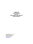
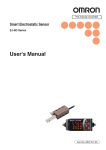
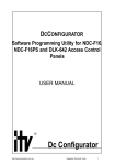
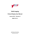
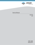
GW15
GS20
GS25
FREESTANDING
COOKER
user manual
imagine the possibilities
Thank you for purchasing this Samsung product.
To receive more complete service, please register
your product at
www.samsung.com/de/global/register/
GENERAL INFORMATION
This appliance complies with the following European Directives:
- 2006/95/EEC regarding “Low Voltage”.
- 2004/108/EEC regarding “Electromagnetic Disturbances”.
- 2009/142/EEC regarding “Gas appliances”
- 89/109/EEC regarding “Materials in contact with food”
- This appliance must be installed in accordance with the regulations in force and must only
be used in well-ventilated rooms. Consult the instructions booklet before installing and using
the appliance.
- This household appliance has been designed for cooking and it must therefore be used for
this purpose only.
DEAR CUSTOMER,
- Carefully read these instructions before using the appliance and keep them for future
consultation.
- Keep potentially hazardous packaging (plastic bags, polystyrene etc.) out of the reach of
children.
WARRANTY
Your new appliance is covered by a warranty.
The warranty certificate is herewith enclosed. If it is missing, ask the retailer for it, indicating purchasing
date, model, and data plate number which are printed on the data nameplate identifing the appliance
(fig. 8F).
Keep the part destined to you, and in case of necessity, show it to the Technical Service together with
the receipt.
If you do not follow this procedure, the Technical Service will be compelled to charge you with all the
fees of each eventual reparation.
You can find the original spare parts only in our Technical Service and Spare Parts Authorised Centres.
TECHNICAL AFTER SALES SERVICE
Before leaving the factory, this appliance has been tested and set up by skilled personal, in order to give
the best performance results.
Each reparation or set up that could be necessary afterwards, must be carried out with a great care and
attention.
For this reason, we reccommend you to keep always in touch with the Sales Centre or with our nearer
After Sales Service. Specify always the kind of problem and the model of your appliance.
ENVIRONMENT PROTECTION
Packing disposal
Sort packing into different materials (cardboard, polystyrene etc.) and dispose of them in
accordance with local waste disposal laws.
GENERAL INFORMATION _1
01 GENERAL INFORMATION
- Moreover the above mentioned Directives comply with Directive 93/68/EEC.
PRECAUTIONS AND GENERAL
RECCOMANDATIONS
ATTENTION:
The use of a gas cooking appliance produces heat and moisture in the room where is installed. Ensure
that the kitchen is well-ventilated: keep natural ventilation holes open or install a mechanical ventilation
device (mechanical extractor hood).
Prolonged intensive use of the appliance may call for additional ventilation, for example opening a
window, or more effective ventilation, for example increasing the level of mechanical ventilation here
present.
Prior to installation, ensure that the local distribution conditions (nature of the gas and gas pressure)
and the adjustment of the appliance are compatible.
- Before using the appliance, do not forget to remove the plastic films protecting some parts
of the appliance (facia-panel, parts in stainless steel, etc.)
- Do not use the appliance as a space heater.
- When the appliance is not in use, we recommend you disconnect the current and close
the gas general tap.
In Case Of Fire:
- In case of fire, close immediately the main valve of the gas pipe line, disconnect the current
and never pour water on firing oil in any case.
- Do not store flammable products or aerosol containers near the burners, and do not
vaporize them near lighted burners.
FOR YOUR SAFETY AND THE ONE OF YOUR CHILDREN.
- Do not store items that are attractive to children above or near the appliance.
- Keep children well away from the appliance: do not forget that some parts of the appliance
or of the pans become very hot and dangerous during use, and it is always necessary to
cool them down.
- In order to avoid any unintentional fall down, pan handles should be turned to the back of
the cooker, not out to the room or over adjacent burners.
- When cooking, do not use clothes with large flaving and flammable sleeves; in case of
firing you can suffer very serious injuries.
- The appliance must not be used be people (including children) with limited physical,
sensory or mental abilities, or without experience or expertise, unless they have received
instructions for using it from those responsible for their safety.
- Young children should be supervised to ensure they not play with the appliance.
Warning - Oven:
When the oven or the grill are in use, accessible parts can become very hot; it is
necessary to keep children away from the appliance.
- Never cook food on the lower wall of the oven.
- In case of careless use, in proximity of the oven door hinges, there is hurt danger.
- Do not let children sit down or play with the oven door. Do not use the drop down door as
a stool to reach above cabinets.
2_ PRECAUTIONS AND GENERAL RECCOMANDATIONS
Lower drawer
You must not place inflammable materials or plastic utensils in the lower drawer (placed
below the oven).
For appliances with glass cover lid
Glass lids may shatter when heated.
Turn off the burners before shutting the lid.
RECCOMANDATIONS AND PRECAUTIONS _3
02 RECCOMANDATIONS
While using the appliance make sure that the glass lid does not touch any pan. After use
never close the glass lid while the burners or the electric hotplates are still hot.
HOW TO USE THE WORK TOP
USING GAS BURNERS
The following symbols are on the control panel next to each knob:
Black circle
gas off
Large flame
maximum setting
Small flame
minimum setting
The minimum position is at the end of the anticlockwise rotation of the knob. All operation must be done
between the positions max. and min., never choose them between max. and off.
Manual ignition
To turn on a burner, approach a match to it, press the knob corresponding to the selected
burner and turn it anticlockwise to the max position.
Electric ignition (according to the models)
To turn on a burner, press the knob corresponding to the selected burner and turn it
anticlockwise to the max position; simultaneously press the electric ignition button on the
symbol.
control panel marked with
In case there is no electric current, the burner can also be lighted using a match.
Automatic electric ignition (according to the models)
To turn on a burner, press the knob corresponding to the selected burner and turn it
anticlockwise to the max position. Keeping the automatic electric ignition button pressed the
burner will be lighted.
In case there is no electric current, the burner can also be lighted using a match.
Appliances with safety valve (according to the models)
Follow the same procedure described above to ignite the burners.
In this case, however, once you have turned the knob to the open setting, hold it pressed in
for 10 seconds.
If for any reason the burner flame goes out, the safety valve automatically shuts off the gas
supply of the burner in question.
ENERGY SAVING TIPS
- The diameter of the pan bottom should be the same as that of the burner. The burner flame
must never come out from the pans diameter.
- Use flat-bottomed pans only.
- Whenever possible, keep a lid on the pan while cooking.
You will not need much heat.
- Cook vegetables, potatoes, etc. with as little water as possible to reduce cooking times.
BURNERS
4_ WORK TOP USE
PANS
RAPID
SEMIRAPID
Ø min.
180 mm
120 mm
Ø max.
320 mm
220 mm
AUXILIARY
TRIPLE CROWN
80 mm
220 mm
180 mm
320 mm
USE OF THE GAS OVEN
BEFORE YOU BEGIN
Clean the oven thoroughly before using for the first time.
The oven is fitted with: a rod shelf for cooking food contained in oven dishes or placed directly
on the rod shelf itself, a drip tray for cooking sweets, biscuits, pizzas, etc., or for collecting
juices and fats from food cooked directly on the rod shelf.
do not cook foods on the bottom in the base of the oven.
Tangential fan
The oven has a cooling fan which is activated and deactivated if necessary during cooking.
The fan stays on for a few minutes even after the oven is switched off.
The hot air escapes through the door.
GAS OVEN
Manual ignition of oven burner
0
25
fig. 1
0
17
210
After making sure that the burner has lit properly,
gently close the oven door.
140
To ignite the oven burner, simply insert a match
through the opening (fig. 2) and then turn the tap
to the maximum setting as shown in fig. 1.
To obtain the temperature required, simply turn
the pointer of the knob to the chosen number.
Do not operate the ignition for more than 15
seconds. If the burner fails to ignite, leave
the oven door open for at least 1 minute
before pressing the knob again.
140°C
250°C
Electric ignition of oven burner
(according to the models)
=
=
=
=
CLOSED
MINIMUM
MAXIMUM
GRILL
1
The oven door must always be completely
open, before the burner ignition.
Turn the knob anticlockwise to the maximum
button to ignite the
position, then press
burner.
In case there is no electric current, the burner
can also be lighted using a match (fig. 2).
fig. 2
Automatic electric ignition
(according to the models)
The oven door must always be completely
open, before the burner ignition.
To ignite the burner, press the knob and turn it
anticlockwise to the maximum position. Keep it
fig. 3
USE OF THE GAS OVEN _5
04 USE OF THE GAS OVEN
Remove accessories and operate the oven at the bake setting at max °C for 1 hour before
using. There will be a distinctive odor; this is normal, but ensure your kitchen is well ventilated
during this conditioning period.
pressed to start up the automatic ignition of the
burner (fig. 3).
Food
In case there is no electric current, the burner
can also be lighted using a match (fig. 2).
Meat
Roast Pork
180-210 °C
Burner with safety device
Roast Beef
Roast Veal
Roast Lamb
Roast Hare
Roast Rabbit
Roast Turkey
Roast Goose
Roast Duck
Roast Chicken
Roast-Beef
Fish
Fruit Cake
Margherita Cake
Brioches
Scones
Ring-Shaped Cake
Puff-Paste
Grapes Cake
Strudel
Savoia Biscuit
Apple Fritter
Pudding
Toast
Bread
250 °C
220 °C
220 °C
230 °C
235 °C
220 °C
235 °C
225 °C
235 °C
200-225 °C
200-225 °C
220 °C
190 °C
175 °C
235 °C
190 °C
200 °C
200 °C
180 °C
290 °C
200 °C
200 °C
250 °C
230 °C
For burners fitted with safety device, it is
necessary to keep on pressing the concerned
knob for about 10 seconds after the ignition
(fig.3). In this way the safety valve will be started
up. If for any reason the burner flame goes out,
repeat the procedure as described above.
When you are sure that the burner is on, close
the oven door softly.
Wait at least 15 minutes before introducing the
food, in order to reach the desired temperature.
Below you will find an indicative cooking table
(tab. C).
To switch on the oven light, press the button
or, depending on the model, turn the knob
(fig. 6).
Tab. C
6_ USE OF THE GAS OVEN
Temp. °C
USE OF THE GAS GRILL
(according to the models)
Manual ignition of the grill
position
05 USE OF THE GAS GRILL
Open the oven door, then turn the oven knob to
the right and place it on the grill
.
Bring a light match near the holes of the burner
placed on the oven upper part (fig.4).
Electric ignition of grill burner
(according to the models)
Turn the knob clockwise to the grill position
to ignite the burner.
then press button
fig. 4
,
In case there is no electric current, the burner
can also be lighted using a match.
Automatic electric ignition
(according to the models)
Automatic electric ignition (according to the
models)
The oven door must always be completely open,
before the burner ignition.
To ignite the burner, press the knob and turn it
. Keep it pressed
clockwise to the grill position
to start up the automatic ignition of the burner.
In case there is no electric current, the burner
can also be lighted using a match (fig.4).
Do not operate the ignition for more than 15
seconds. If the burner fails to ignite, leave
the oven door open for at least 1 minute
before pressing the knob again.
USE OF THE GAS GRILL _7
Burner with safety device
Repeat the above mentioned procedure, and
press the oven knob at the same time. When the
burner is on, keep the knob pressed for about 10
seconds (fig.3). In this way the safety valve will
be started up. If for any reason the burner flame
goes out, repeat the procedure as described
above.
Heat the oven for 5 minutes, before introducing
the food.
This device ensures that the gas supply is shut
off if the flame on the gas burner is extinguished
while the burner is in use.
fig. 5A
NOTE: The grill must be used with the door
half-open (fig. 5A). Fit the deflector S onto the
centring pins N on the top of the oven opening
(fig. 5B). Then gently close the oven door against
the deflector.
S
fig. 5B
8_ USE OF THE GAS GRILL
USE OF THE TURNSPIT
Turn the knob to the position
.
with the symbol
(fig. 6) to use the turnspit or, in some models, press the button marked
MULTILPE TURNSPIT
06 USE OF THE TURNSPIT
Follow the instructions described below to use the
turnspit.
- Thread the chicken or the slices of meat to
roast on the spit L , ensuring that it is gripped
safely between the two forks F and balancing
it properly to avoid unnecessary strain on the
trasmission R (fig. 6A).
- Put the spit on the support G, after having
introduced its opposite end into the socket P
of the transmission R (fig. 6A)
fig. 6
- Put the support G completely into the oven so
that the bar I goes into the socket H of the
turnspit motor M (fig. 6B).
- Place the drip tray with some water under the
turnspit, on the lowest level.
- The turnspit must be used with the oven door
open (fig. 5A); fit the deflector S onto the
centring pins N on the top of the oven opening
(fig.5 B ).
P
G
fig. 6A
- when removing the spit, wear oven mitts, pull
out support G.
I
fig. 6B
SINGLE TURNSPIT
Follow the instructions described below to use the
turnspit.
fig. 7
- Put the food in spit L (fig. 7), paying attention
to block it within the two forks F and to balance
it, in order to avoid any unnecessary effort in
motor R.
- Put the spit on support G, after having put its
opposite end into hole P of motor R.
L
- Place the drip tray with a little water under the spit.
The turnspit must be used with the oven
door open (fig. 5A); fit the deflector S onto the
centring pins N on the top of the oven opening
(fig.5 B ).
- To remote the spit, operate in the opposite
direction using protecting gloves of isolating
wool (fig.7).
USE OF THE TURNSPIT _9
INSTRUCTIONS FOR USE OF
CONTROL DEVICES
(according to the models)
MINUTES COUNTERS (FIG. 8)
Turn the knob clockwise to set the desired cooking time.
The minutes minder can be adjusted from 1 to 60
minutes.
A sound signal will inform you that the chosen time is up.
55
50
10
5
15
45
20
40
30
25
fig. 8
35
ELECTRONIC TIMER FOR THE
COOKER
On
The display flashes.
Time setting
Press the left button.
Set the time with buttons “+” and “-”.
This function remains activated for 7 seconds
after the last +/- operation.
Timer setting
This function is permanently activated and it will
be immediately set with +/- buttons.
fig 8B
During setting the units are of 10 seconds.
1 Time of the day
During count down the timer takes priority on 2 Timing and insertion
the display.
3 Signal timng and insertion
The units are seconds.
The maximum time is 99 minutes.
Reset timer
Press “+” and “-” buttons together and release “+” button first.
Signal
The signal will be maintained for 7 minutes if it has not been reset with the “+” button (one
touch only).
Signal frequency
When the display shows the time of day, the signal frequency can be selected by pressing the
“-” button. Three different frequencies can be selected.
10_ INSTRUCTIONS FOR USE OF CONTROL DEVICES
ELECTRICAL CONNECTION
Connection to the main supply of the appliance must
be done in accordance with the rules in force, and only
by an authorized technician.
L
THIS APPLIANCE MUST BE EARTHED
N
08 ELECTRICAL CONNECTION
Check that the power rating of the mains supply and of
the sockets are suitable for the maximum power of the
appliance as indicated on the specification plate. If the
appliance isn't already fitted with a plug, fit a regulation
plug to the cable which is capable of taking the power
indicated on the specification plate (fig. 8F ).
*
The earth wire is yellow/green. If the plug fitted to the
appliance, and the socket, are not compatible, get a
profesionnally qualified technician to fit the correct type
of a plug. If an appliance is not equipped with a supply
cable and a plug, the power supply must be fitted with a
disconnect switch in which the distance between contacts
permits total disconnection in accordance with overvoltage
category III, as required by installation regulations.
The yellow/green earth wire should not be controlled
by the switch.
The plug used for mains supply connection should be easy
to get at, once the appliance is in position.
Position the mains supply cable so that it is never
subjected to a temperature which is more than
50°C above ambient temperature.
The electrical safety of the appliance can only be guaranteed
when it has been correctly connected to an efficient earthed
power supply, as laid down in the regulations for electrical
safety.
The manufacturer cannot be held responsible for
any damage to persons or objects due to the
lack of an earth connection.
TYPE AND SECTION OF SUPPLY CABLE
Appliance
type
All gas
Alimentation monophase
230 V~
Type of
section
cable
Rubber H05
3 x 0,75 mm2
RR-F
If the supply cable is damaged, it must be
replaced by the manufacturer or by his aftersales service, or by a similar qualified person, in
order to prevent any risk.
ELECTRICAL CONNECTION _11
CARE AND MAINTENANCE
Before cleaning the appliance, disconnect the gas general tap and unplug the appliance or
disconnect the power at the main circuit breaker of the electrical system.
Do not use steam cleaners to clean the oven.
Do not clean the appliance surfaces while it is still hot.
Periodically check the external gas connection hole and replace it when it shows any sign of
deterioration. Do not attempt to repair the gas hose under any circumstances.
ENAMELLED SURFACES
Clean with a damp sponge using soap and water.
Grease can be easily removed using hot water or a specific cleansing agent for enamelled surfaces. Do
not use abrasive cleansers.
Do not leave any acid or alkaline substances (lemon juice, vinegar, salt, etc.) on the enamel.
Clean the parts in stainless steel with specific cleansers for stainless steel surfaces.
These detergents must be applied using a soft cloth.
GRIDS AND BURNERS
To clean the work top burners, remove them by pulling
upwards and soak them for about 10 minutes in hot water
with a little detergent. After having cleaned and washed
them, wipe them carefully.
Make sure that no burner hole is clogged.
fig. 8D
Clean the burners once a week or more frequently if
necessary.
MAKE SURE YOU HAVE ASSEMBLED THE BURNERS IN
A RIGHT WAY.
Side Grills (depending of the model)
The oven side grills are secured on three pins
and can be removed by pressing down lightly as
shown in fig. 8C.
Interior glass of the oven (for some
models only)
The interior glass of the oven door can be
removed: with the door in a semi-open position,
remove the glass as shown in figures 8D.
After cleaning, refit the glass by proceeding in
reverse order.
12_ CARE AND MAINTENANCE
fig. 8C
OVEN DOOR (FIG. 8E)
For some models, the oven door can be disassembled in
the following way:
fig. 8E
Before closing the door, do not forget to remove the movable jumpers B.
Attention, in proximity of the oven door hinges, there is hurt danger.
CAUTION: Do not use rough or abrasive materials or sharp metal scrapers to clean
the glass doors of the oven since they may scratch the surface and cause the glass to
break.
OVEN
Clean the enamelled parts with a damp sponge using soap and water. Grease can be easily removed
using hot water or a specific cleansing agent for enamelled surfaces.
Do not use abrasive cleansers.
CARE AND MAINTENANCE _13
09 CARE AND MAINTENANCE
- hinges A are provided, for this purpose, with
two movable jumpers B; these block them,
once hooked to the hinges slots C, when the
door is completely opened. After that lift the
door outward carring out the two movements
shown in the picture. To do that, operate on
the door sides next to the hinges. In order to
re-assemble the door, introduce the hinges in
their relevant slots.
USER INSTRUCTIONS
OVERALL DIMENSIONS WARNINGS
A = 25 mm according to the models
B = Adjustable legs (100 / 150mm)
895
600
B
725
A
60
600
A = 30 mm according to the models
The technical data are indicated on the data nameplate placed on the rear of the
appliance.
The adjustment conditions are stated on the label applied on the packaging and on the
appliance.
Do not use the oven door handle to move the appliance, such as to remove it from the
packaging.
The appliance is in class 1 or class 2, subclass 1.
INSTALLATION
The coating of the furniture must be able to withstand high temperatures (min. 90°C).
If the appliance is to be installed near units, leave the minimum gaps specified in the
figure 8G.
CAUTION : The cooker must not be placed on a pedestal.
The cooker is fitted with 4 legs for an eventual alignment in height with the furniture. To assemble
them, it is necessary to raise the cooker and to screw the four legs into the suitable threadings
placed on the corners on the bottom of the appliance (fig. 8H).
14_
INSTRUCTIONS DESTINED TO THE USER
Gas appliances
This appliance is not connected to a device to
vent the combustion products. It must therefore
be installed and connected in conformity with
the installation standards in force.
Particular attention must be paid to the
standards on room ventilation.
Room ventilation
In particular when there is only this gas
appliance in the room, there must be a hood
over the appliance to ensure the natural and
direct removal of spent air, with a vertical
straight duct of length equal to at least twice
the diameter and a minimum section of at
least 100 cm 2.
10 USER INSTRUCTIONS
Remember that this appliance can be
installed and work in well-ventilated rooms
only, according to the standards in force.
The openings on the external walls or the
spacial ducts allow a correct natural or
forced ventilation, ensuring permanently and
sufficiently the entry of the air needed for the
correct combustion and the removal of the
spent air.
fig. 8F
OK
O
fig. 8 H
For the indispensable entry of fresh air into
the room there must be a similar 100 cm 2
opening directly to the outside, situated at a
height near floor level so that it is not blocked
either inside or outside the wall and not to
cause disturbances to the correct burners
combustion and to the regular removal of
spent air and with a difference of height
with respect to the outlet opening of at least
180 cm (fig. 8L).
Remember that the quantity of air necessary
for the combustion must never be less than
min. 0 mm
min. 20mm
00 mm
min. 20mm
min.
min. 00 mm
min.
0 mm
min. 0 mm
fig. 8G
INSTRUCTIONS DESTINED TO THE USER
_15
2m 3 /h for each kW of power (see total power
in kW on the appliance data plate fig. 8F ).
min. 180 cm.
*
In all the other cases, i.e. when there are other
gas appliances in the same room, or when
natural direct ventilation is not possible and
natural indirect or forced ventilation must be
installed, contact a qualified specialist who
will install and make the ventilation system,
scrupulously
observing
the
regulations
contained in the standards in force.
The openings must be so positioned that
there are no draughts of air which cannot be
tolerated by the occupants.
min. 100cm2.
Moreover to eliminate combustion products, it
is forbidden to use flues already used by other
appliances.
ic n
min. 180 cm.
c
min. 100cm2.
fig. 8 L
16_ INSTRUCTIONS DESTINED TO THE USER
GAS CONNECTION
We recommend to check wether the appliance has been
foreseen for the kind of gas distributed.
(G 1/2) ISO 228-1
The appliance must be connected to the gas piping in a
workmanlike way and in conformity with the regulations in
force which lay down the installation of a safety valve at the
end of the piping.
2
F
F
fig. 9A
Once the gas appliance has been connected, check the
connection seal by means of soapy water.
1:Hose attachment for liquid gas
2:Hose attachment for natural gas
The possible connections are:
1)
by the insertion of a rubber tube in accordance
with the rules.
(G 1/2) ISO 228-1
This tube must be connected directly on the
push-on connector, concerning the gas used,
and it must be blocked with a band.
In the last case, check the tube's printed date of
expiry and replace it before this date (Fig. 9A).
2)
by rigid pipe in iron or copper.
fig. 9B
3)
by flexible tube in stainless steel with continuing
wall, with mechanical connection in accordance
with rules. The tube must be directly connected
to the manifold elbow (Fig.9B).
Concerning rubber flexible tubes, we remember
you:
- to avoid the tube to be narrowed or crushed
- do not submit it to traction or torsion efforts
- to avoid contact with sharp edges, etc...
- to avoid contact
temperatures over
temperature
with parts
70°C the
reaching
ambient
- to ensure that they can be checked for all their
length.
Note: If the cooker has to be connected on the
opposite side, run the flexible tube as shown in
the figure 10.
fig. 10
GAS CONNECTING _17
11 GAS CONNECTION
For butane and propane a pressure reducer conforming
to the standards in force may perform this task. The seal
gaskets must be in accordance with rules.
1
GAS ADJUSTMENT
If the appliance is foreseen to operate with a type of gas different from the suitable supply gas, proceed as
follows: change the injectors, adjust the minimum flow of the burners, change the push-on connector.
In order to change the work top injectors, it is necessary to act as follows: remove the grids, remove
burners and flame-spreaders (fig. 10A), change the injector (fig. 10B) and replace it with another one
suitable for the new type of gas (see general injectors table in page 21). Re-assemble everything in the
opposite direction, paying attention to place the flame-spreader in the right way on the burner.
To change the oven injector, it is necessary to act as follows: open the oven door, remove the lower side
of the oven (fig. 10C), unscrew screw C and disassemble the oven burner (fig. 10D). Change the injector
(fig. 10E) and replace it with another one suitable for the new gas type (see table D).
Re-assemble everything in the opposite direction, paying attention to place the burner in the right way
on its rear slot.
To change the grill injector, it is necessary to act as follows: open the oven door, unscrew screw C and
disassemble the grill burner (fig. 10F / 10F1). Change the injector (fig. 10G) and replace it with another
one suitable for the new gas type (see general injectors table in page 21).
Re-assemble everything in the opposite direction, paying attention to place the burner in the right way
on its rear slot.
fig. 10A
fig. 10B
fig. 10C
C
fig. 10D
fig. 10E
C
fig. 10F
18_ GAS ADJUSTMENT
fig. 10F1
fig. 10G
GENERAL INJECTORS TABLE
Tipe of gas
mbar
Nozzle N.
Burners
Position-type
min. rated
NATURAL
17
30
28
37
max.
min.
1.15
0.97
0.72
1.28
1.50
1.45
Rapid
Semirapid
Auxiliary
Triple crown
Oven
Grill
3000
1750
1000
3300
4300
3800
750
480
330
1300
0.85
0.65
0.50
0.93
1.00
0.95
Rapid
Semirapid
Auxiliary
Triple crown
Oven
Grill
3000
1750
1000
3300
4300
3800
750
480
330
1300
Consum.
max
286
167
95
315
389
344
219
128
73
241
213
277
l/h
l/h
l/h
l/h
l/h
l/h
g/h
g/h
g/h
g/h
g/h
g/h
MINIMUM FLOW ADJUSTMENT FOR WORK TOP TAPS
In order to adjust the minimum, act as follows: switch the
burner on, and turn the knob towards the minimum flow
position . Remove the knob from the tap, introduce a
little screwdriver in the tap rod (fig. 11).
Attention: in taps with security valve, the minimum adjusting
screw “Z” is placed outside the rod tap (fig. 12).
Unscrew the adjusting screw in order to increase the flow
or screw it to decrease the flow.
The right adjustment is obtained when the flame has a
length of about 3 or 4 mm.
fig. 11
For butane/propane gas, the adjusting screw must be tight
screwed.
Z
Make sure that the flame does not go out passing
to the minimum flow
and
quickly from the max. flow
viceversa.
Assemble the knob again.
fig. 12
GAS ADJUSTMENT _19
12 GAS ADJUSTMENT
G.P.L.
BUTANE
PROPANE
20
Power Watt
MINIMUM FLOW ADJUSTMENT FOR OVEN THERMOSTAT
In order to adjust the minimum, act as follows: switch the
burner on turning the knob to the maximum position.
Remove the knob and unscrew of some turns the by-pass
screw (fig. 12A).
Assemble the knob and let the oven warm up for 15 minutes;
after that turn the knob to the minimum position.
After having removed the knob once again, make sure that
the thermostat rod has not been moved, and screw slightly
the above mentioned by-pass screw, in order to obtain a
flame of 3 or 4 mm of length.
For butane/propane gas, the adjusting screw must be tight
screwed. Make sure that the flame does not extinguish
passing quickly from the maximum flow to the minimum
flow, and closing and opening the oven door (the oven door
must be closed softly).
fig. 12A
T
Attention: for taps with safety device, the minimum adjusting
screw “T” is on the outside of the tap rod (fig. 12B).
fig. 12B
20_ GAS ADJUSTMENT
REGULATION OF THE
AIR ADJUSTER
REGULATION OF THE AIR ADJUSTER (OVEN BURNER )
In this way, entrace of the air increases or descreases,
obtaining a correct flame.
Be sure that the flame does not lift or light back or present
a yellow colouration.
A
REGULATION OF THE AIR ADJUSTER
(GRILL BURNER )
fig. 13A
Unscrew the screw (A) in order to slip it forwards or
backwards (fig. 13B).
In this way, entrace of the air increases or descreases,
obtaining a correct flame.
Be sure that the flame does not lift or light back or present
a yellow colouration.
On completion of all the burner gas type
conversion operations, re-do all the seals on the
air supply controls.
A
fig. 13B
APPLIANCE MAINTENANCE
Isolate the cooker from the electricity supply
before attempting to replace the oven lamp.
The oven lamp used is of a special type
withstanding high temperatures. To replace it,
act as follows: disassemble the protecting glass
(A) and replace the burnt lamp with one of the
same type (fig. 14). Reassemble the protecting
glass.
E 14
25 W - 230 V~
T300°C
A
fig. 14
fig. 15
REGULATION AIR ADJUSTER _21
15 AIR ADJUSTER
Unscrew the screw (A ) in order to rotate the metal ring at
the end of the burner (fig. 13A).
DISASSEMBLE OF WORK TOP
In case it is necessary to repair or replace the inside
components, act as follows:remove the glass lid from its
position slipping off it upwards.
Remove the grids, remove burners and flame-spreaders
(fig. 15), unscrew the visible screws “V” placed on the work
top (fig. 15A). Disassemble the work top by unscrewing the
4 rear screws “A” (fig. 15B).
fig. 15B
fig. 16
V
fig. 15A
A
B
To disassemble the control panel, unscrew the 4 internal screws (B) fixing the control panel to the oven
face (fig. 16).
22_ REGULATION AIR ADJUSTER
QUESTIONS OR COMMENTS?
COUNTRY
CALL
OR VISIT US ONLINE AT
FAX no.
CANADA
1-800-SAMSUNG(726-7864)
www.samsung.com/ca
1-866-436-4617
MEXICO
01-800-SAMSUNG(726-7864)
www.samsung.com/mx
01.800.849.1743
U.S.A
1-800-SAMSUNG(726-7864)
www.samsung.com/us
(973)601-6001
ARGENTINE
0800-333-3733
www.samsung.com/ar
BRAZIL
0800-124-421
4004-0000
www.samsung.com/br
CHILE
800-SAMSUNG(726-7864)
www.samsung.com/cl
NICARAGUA
00-1800-5077267
www.samsung.com/latin
HONDURAS
800-7919267
www.samsung.com/latin
COSTA RICA
0-800-507-7267
www.samsung.com/latin
ECUADOR
1-800-10-7267
www.samsung.com/latin
EL SALVADOR
800-6225
www.samsung.com/latin
GUATEMALA
1-800-299-0013
www.samsung.com/latin
JAMAICA
1-800-234-7267
www.samsung.com/latin
PANAMA
800-7267
www.samsung.com/latin
PUERTO RICO
1-800-682-3180
www.samsung.com/latin
REP. DOMINICA
1-800-751-2676
www.samsung.com/latin
56-2-485-8502
TRINIDAD & TOBAGO
1-800-SAMSUNG(726-7864)
www.samsung.com/latin
VENEZUELA
0-800-100-5303
www.samsung.com/latin
COLOMBIA
01-8000112112
www.samsung.com.co
BELGIUM
02 201 2418
www.samsung.com/be (Dutch)
www.samsung.com/be_fr (French)
CZECH REPUBLIC
800 - SAMSUNG (800-726786)
www.samsung.com/cz
DENMARK
8 - SAMSUNG(7267864)
www.samsung.com/dk
FINLAND
30 - 6227 515
www.samsung.com/fi
FRANCE
01 48 63 00 00
www.samsung.com/fr
01 48 63 06 38
GERMANY
01805 - SAMSUNG(726-7864 € 0,14/Min)
www.samsung.de
01805 - 121214
HUNGARY
06-80-SAMSUNG(726-7864)
www.samsung.com/hu
ITALIA
800-SAMSUNG(726-7864)
www.samsung.com/it
LUXEMBURG
02 261 03 710
www.samsung.com/lu
NETHERLANDS
0900-SAMSUNG (0900-7267864)
(€ 0,10/Min)
www.samsung.com/nl
NORWAY
3 - SAMSUNG(7267864)
www.samsung.com/no
POLAND
0 801 1SAMSUNG(172678)
022-607-93-33
www.samsung.com/pl
PORTUGAL
80820-SAMSUNG(726-7864)
www.samsung.com/pt
SLOVAKIA
0800-SAMSUNG(726-7864)
www.samsung.com/sk
SPAIN
902 - 1 - SAMSUNG (902 172 678)
www.samsung.com/es
6001278
(+420) 225 020 789
02 92141801
+48-22-607 4448
SWEDEN
075 - SAMSUNG(726 78 64)
www.samsung.com/se
U.K
0845 SAMSUNG (7267864)
www.samsung.com/uk
0845 650 8080
EIRE
0818 717 100
www.samsung.com/ie
+44 (0)131 202 0630
AUSTRIA
0810 - SAMSUNG(7267864, € 0.07/min)
www.samsung.com/at
SWITZERLAND
0848 - SAMSUNG(7267864, CHF 0.08/
min)
www.samsung.com/ch
RUSSIA
8-800-555-55-55
www.samsung.ru
+7-495-783-0556
KAZAKHSTAN
8-10-800-500-55-500
www.samsung.com/kz_ru
+7 (727) 258-59-66
UZBEKISTAN
8-10-800-500-55-500
www.samsung.com/kz_ru
+998-71-120-7208
KYRGYZSTAN
00-800-500-55-500
TADJIKISTAN
8-10-800-500-55-500
‘+996 312 934 555
UKRAINE
8-800-502-0000
www.samsung.ua
380 (44) 390 5334
LITHUANIA
8-800-77777
www.samsung.com/lt
+370 52 139 770
LATVIA
8000-7267
www.samsung.com/lv
+371 67 50 84 80
ESTONIA
800-7267
www.samsung.com/ee
+372 6579089
AUSTRALIA
1300 362 603
www.samsung.com/au
(612) 9763 5750
NEW ZEALAND
0800 SAMSUNG (0800 726 786)
www.samsung.com/nz
CHINA
800-810-5858
400-810-5858
010-6475 1880
www.samsung.com/cn
HONG KONG
3698-4698
www.samsung.com/hk
INDIA
3030 8282
1800 110011
1800 3000 8282
www.samsung.com/in
INDONESIA
0800-112-8888
www.samsung.com/id
(021)5694-2525
JAPAN
0120-327-527
www.samsung.com/jp
+81-3-3527-5533
MALAYSIA
1800-88-9999
www.samsung.com/my
03-7711-7299
PHILIPPINES
1-800-10-SAMSUNG(726-7864)
1-800-3-SAMSUNG(726-7864)
02-5805777
www.samsung.com/ph
SINGAPORE
1800-SAMSUNG(726-7864)
www.samsung.com/sg
(65) 6568 7576
THAILAND
1800-29-3232
02-689-3232
www.samsung.com/th
02-689-3298
TAIWAN
0800-329-999
www.samsung.com/tw
(84)-8-825-1128
VIETNAM
1 800 588 889
www.samsung.com/vn
(084) 08-8235808
TURKEY
444 77 11
www.samsung.com/tr
90 (0)212 288 5657
SOUTH AFRICA
0860-SAMSUNG(726-7864 )
www.samsung.com/za
27-11-549-1704
27-11-549-1726
U.A.E
800-SAMSUNG (726-7864)
8000-4726
www.samsung.com/ae
971-4-881-3215
24_
3698 4666