1
Contents
Safety Precautions
.........................................................................................
........................................................................................................
Selecting the Installation Location ........................................................
Indoor Unit Installation ...............................................................................
Purging the Unit .............................................................................................
Connecting the Refrigerant Pipe ............................................................
Cutting/Flaring the Pipes ...........................................................................
Performing Leak Test & Insulation .........................................................
Drainpipe and Drain Hose Installation ................................................
Wiring Work ......................................................................................................
Indoor Unit Setting .......................................................................................
Additional Functions ....................................................................................
Final Checks and User Tips ........................................................................
Troubleshooting .............................................................................................
Accessories
3
5
6
12
14
15
16
17
19
22
25
26
27
28
E-2
AVXC1@@_IM_E_29824-2_12.14.09.indd 2
2009-12-14 17:38:35
Safety Precautions
(Carefully follow the precautions listed below because they are essential to guarantee the safety of the equipment.)
WARNING
• Always disconnect the air conditioner from the power supply before servicing it or
accessing its internal components.
• Verify that installation and testing operations are performed by qualified personnel.
• Verify that the air conditioner is not installed in an easily accessible area.
GENERAL INFORMATION
Carefully read the content of this manual before installing the air conditioner and store the manual in a safe place in order to be
able to use it as reference after installation.
For maximum safety, installers should always carefully read the following warnings.
Store the operation and installation manual in a safe location and remember to hand it over to the new owner if the
air conditioner is sold or transferred.
This manual explains how to install an indoor unit with a split system with two SAMSUNG units. The use of other types of units
with different control systems may damage the units and invalidate the warranty. The manufacturer shall not be responsible for
damages arising from the use of non compliant units.
The manufacturer shall not be responsible for damage originating from unauthorized changes or the improper connection of electric
and hydraulic lines. Failure to comply with these instructions or to comply with the requirements set forth in the “Operating limits”
table, included in the manual, shall immediately invalidate the warranty.
The air conditioner should be used only for the applications for which it has been designed: the indoor unit is not suitable to be
installed in areas used for laundry.
Do not use the units if damaged. If problems occur, switch the unit off and disconnect it from the power supply.
In order to prevent electric shocks, fires or injuries, always stop the unit, disable the protection switch and contact SAMSUNG’s
technical support if the unit produces smoke, if the power cable is hot or damaged or if the unit is very noisy.
Always remember to inspect the unit, electric connections, refrigerant tubes and protections regularly. These operations should be
performed by qualified personnel only.
The unit contains moving parts, which should always be kept out of the reach of children.
Do not attempt to repair, move, alter or reinstall the unit. If performed by unauthorized personnel, these operations may cause
electric shocks or fires.
Do not place containers with liquids or other objects on the unit.
All the materials used for the manufacture and packaging of the air conditioner are recyclable.
The packing material and exhaust batteries of the remote control(optional) must be disposed of in accordance with current laws.
The air conditioner contains a refrigerant that has to be disposed of as special waste. At the end of its life cycle, the air conditioner
must be disposed of in authorized centers or returned to the retailer so that it can be disposed of correctly and safely.
INSTALLING THE UNIT
IMPORTANT: When installing the unit, always remember to connect first the refrigerant tubes, then the electrical lines.
Always disassemble the electric lines before the refrigerant tubes.
Upon receipt, inspect the product to verify that it has not been damaged during transport. If the product appears damaged,
DO NOT INSTALL it and immediately report the damage to the carrier or retailer (if the installer or the authorized technician has
collected the material from the retailer.)
After completing the installation, always carry out a functional test and provide the instructions on how to operate
the air conditioner to the user.
Do not use the air conditioner in environments with hazardous substances or close to equipment that release free flames to avoid
the occurrence of fires, explosions or injuries.
The air conditioner should be used only for the applications for which it has been designed: the indoor unit is not suitable to be
installed in areas used for laundry.
Our units must be installed in compliance with the spaces indicated in the installation manual to ensure either accessibility from
both sides or ability to perform routine maintenance and repairs. The units’ components must be accessible and that can be
disassembled in conditions of complete safety either for people or things.
For this reason, where it is not observed as indicated into the Installation Manual, the cost necessary to reach and repair the unit (in
safety, as required by current regulations in force) with slings, trucks, scaffolding or any other means of elevation won’t be
considered in-warranty and charged to end user.
POWER SUPPLY LINE, FUSE OR CIRCUIT BREAKER
Always make sure that the power supply is compliant with current safety standards. Always install the air conditioner in compliance
with current local safety standards.
Always verify that a suitable grounding connection is available.
Verify that the voltage and frequency of the power supply comply with the specifications and that the installed power is sufficient
to ensure the operation of any other domestic appliance connected to the same electric lines.
Always verify that the cut-off and protection switches are suitably dimensioned.
Verify that the air conditioner is connected to the power supply in accordance with the instructions provided in the wiring
diagram included in the manual.
Always verify that electric connections (cable entry, section of leads, protections…) are compliant with the electric specifications
and with the instructions provided in the wiring scheme. Always verify that all connections comply with the standards applicable
to the installation of air conditioners.
AVXC1@@_IM_E_29824-2_12.14.09.indd 3
E-3
2009-12-14 17:38:35
Safety Precautions (Continued)
CAUTION
Make sure that you earth the cables.
- Do not connect the earth wire to the gas pipe, water pipe, lighting
rod or telephone wire. If earthing is not complete, electric shock or
fire may occur.
Install the circuit breaker.
- If the circuit breaker is not installed, electric shock or fire may occur.
Make sure that the condensed water dripping from the drain hose
runs out properly and safely.
Install the power cable and communication cable of the indoor and
outdoor unit at least 1m away from the electric appliance.
Install the indoor unit away from lighting apparatus using the ballast.
- If you use the wireless remote control, reception error may occur
due to the ballast of the lighting apparatus.
Do not install the air conditioner in following places.
- Place where there is mineral oil or arsenic acid.
Resin parts flame and the accessories may drop or water may leak.
The capacity of the heat exchanger may reduce or the air conditioner
may be out of order.
- The place where corrosive gas such as sulfurous acid gas generates
from the vent pipe or air outlet.
The copper pipe or connection pipe may corrode and refrigerant
may leak.
- The place where there is a machine that generates electromagnetic
waves.
The air conditioner may not operate normally due to control system.
- The place where there is a danger of existing combustible gas,
carbon fiber or flammable dust.
The place where thinner or gasoline is handled.
Gas may leak and it may cause fire.
Our units must be installed in compliance with the spaces indicated in
the installation manual to ensure either accessibility from both sides
or ability to perform routine maintenance and repairs. The units’
components must be accessible and that can be disassembled in
conditions of complete safety either for people or things.
E-4
AVXC1@@_IM_E_29824-2_12.14.09.indd 4
2009-12-14 17:38:36
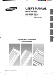
Accessories
The following accessories are supplied with the indoor unit.
The type and quantity may differ depending on the specifications.
AVXC1/AVXCS/AVXC2
Pattern sheet
Insulation drain
Flexible hose
Rubber
Insulation cover band
Pattern sheet
Insulation cover band
Insulation drain hose
Insulation pipe
Cable-tie
Flexible hose
M4x12 tapped Screw
Insulation drain sub
Pad stopper
Installation manual
Cable-tie
Installation manual
AVXC4
Safety net
M4x12 tapped Screw
AVXCM
Pattern sheet
Insulation cover band
Insulation drain hose
Insulation pipe
Flexible hose
M4x12 tapped Screw
Pad stopper
Installation manual
Safety net
M4x12 tapped Screw
E-5
AVXC1@@_IM_E_29824-2_12.14.09.indd 5
2009-12-14 17:38:38
Selecting the Installation Location
Indoor Unit
There must be no obstacles near the air inlet and outlet.
Install the indoor unit on a ceiling that can support its weight.
Maintain sufficient clearance around the indoor unit.
Make sure that the water dripping from the drain hose runs away
correctly and safely.
The indoor unit must be installed in this way, that they are out of public
access. (Not touchable by the users)
Rigid wall without vibration.
Where it is not exposed to direct sunshine.
Where the air filter can be removed and cleaned easily.
CAUTION
As a rule, the unit cannot be installed at a height of less than 2.5 m.
It is possible to install the unit at a height of between 2.2~2.5m from
the ground, if the unit has a duct with a well defined length (300mm or
more) to avoid fan motor blower contact.
Space Requirements for Indoor Unit
AVXC1/AVXCS/AVXC2
AVXC4/AVXCM
E-6
AVXC1@@_IM_E_29824-2_12.14.09.indd 6
2009-12-14 17:38:39
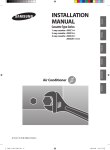
Dimension of the indoor unit
AVXC1
Unit : mm
No.
Name
Description
Liquid pipe connection
Gas pipe connection
Drain pipe connection
Power supply connection
-
Air discharge grille
-
Air suction grille
-
ø6.35 (1/4”)
ø12.70 (1/2”)
VP20 (OD ø26, ID ø20)
E-7
AVXC1@@_IM_E_29824-2_12.14.09.indd 7
2009-12-14 17:38:39
Selecting the Installation Location (Continued)
Dimension of the indoor unit
AVXCS
���
���
Unit : mm
���
���
����
����
���
��
���
Drain hole
����
No.
Name
Description
Liquid pipe connection
ø6.35 (1/4”)
Gas pipe connection
ø12.70 (1/2”)
Drain pipe connection
OD ø29, ID ø25
Power supply connection
-
Air discharge grille
-
Air suction grille
-
E-8
AVXC1@@_IM_E_29824-2_12.14.09.indd 8
2009-12-14 17:38:42
AVXC2
Unit : mm
493
890
919
25
136.5
157
650
72.5
1030
575
117
230
180
No.
Name
Description
056: ø6.35 (1/4”)
071: ø9.52 (3/8”)
056: ø12.70 (1/2”)
071: ø15.88 (5/8”)
Liquid pipe connection
Gas pipe connection
Drain pipe connection
Power supply connection
-
Air discharge grille
-
Air suction grille
-
VP25 (OD ø32, ID ø25)
E-9
AVXC1@@_IM_E_29824-2_12.14.09.indd 9
2009-12-14 17:38:51
Selecting the Installation Location (Continued)
AVXC4
Unit : mm
5
6
AVXC4045/056/071/090
57
57
840
260
290
25
41
208
100
80
230
64
160
190
166
218
344
178
25
1000mm
242
246
305
322
AVXC4112/128/140
57
310
840
260
290
25
57
322
242
246
305
4
No.
1
1000 or more
64
160
190
200
25
208
57
840
158
138
68
258 Adjustable
3
41
298
457
57
2
Name
Liquid pipe connection
Gas pipe connection
Drain pipe connection
Description
045/056ø6.35 (1/4”)
071/090/112/128/140ø9.52 (3/8”)
045/056ø12.70 (1/2”)
071/090/112/128/140ø15.88 (5/8”)
OD ø32, ID ø26
Power supply connection
-
Air discharge grille
-
Air suction grille
-
E-10
AVXC1@@_IM_E_29824-2_12.14.09.indd 10
2009-12-14 17:38:54
AVXCM
Unit : mm
No.
Name
Description
Liquid pipe connection
ø6.35 (1/4")
Gas pipe connection
ø12.70 (1/2”)
Drain pipe connection
Power supply connection
-
Air discharge grille
-
Air suction grille
-
VP25 (OD ø32, ID ø25)
E-11
AVXC1@@_IM_E_29824-2_12.14.09.indd 11
2009-12-14 17:39:16
Indoor Unit Installation
It is recommended to install the Y-joint before installing the indoor unit.
1
Place the pattern sheet on the ceiling at the spot where you want to
install the indoor unit.
Note
Concrete
Since the diagram is made of paper, it may shrink or stretch
slightly due to temperature or humidity. For this reason,
before drilling the holes maintain the correct dimensions
between the markings.
2
Insert bolt anchors, use existing ceiling supports or construct a suitable
support as shown in figure.
3
Install the suspension bolts depending on the ceiling type.
Insert
Hole in anchor
Hole in plug
Suspension bolt(3/8" or M10)
Ceiling support
CAUTION
Ensure that the ceiling is strong enough to support
the weight of the indoor unit. Before hanging the unit,
test the strength of each attached suspension bolt.
If the length of suspension bolt is more than 1.5m,
it is required to prevent vibration.
If this is not possible, create an opening on the false
ceiling in order to be able to use it to perform the required
operations on the indoor unit.
E-12
AVXC1@@_IM_E_29824-2_12.14.09.indd 12
2009-12-14 17:39:23
4
Nut
Screw eight nuts to the suspension bolts making space for hanging the
indoor unit.
CAUTION
5
Washer
You must install the suspension bolts more than four when
installing the indoor unit.
Rubber
Check the level of the indoor unit by using a leveler.
A tilt of the indoor unit may cause malfunction of a built-in float switch
and water leaks.
6
Fasten the nut
Adjust the height of the indoor unit by using the gauge of dimensions.
You should adjust the gauge of dimensions and the pattern sheet to fit
the cutting dimensions of ceiling.
Make sure that the indoor unit is installed at a level if the indoor unit
slants too much, there can be water leaks.
AVXC1
Level
AVXCS
Ceiling
Gauge of Dimensions
AVXC2
Air inlet
15mm
Air
outlet
15mm
Air
inlet
����
����
Side view
Air outlet Ceiling
Gauge of Dimensions
AVXC4
Indoor Unit
20mm
Ceiling
����
35mm
����
Ceiling
Ceiling
Gauge of
Dimensions
AVXCM
Indoor Unit
20mm
Ceiling
17mm
Gauge of
Dimensions
7
Tighten the upper part nuts.
8
Remove the gauge of dimensions after installing the indoor unit.
E-13
AVXC1@@_IM_E_29824-2_12.14.09.indd 13
2009-12-14 17:39:24
Purging the Unit
From factory the unit is supplied and set with a pre-charge of nitrogen gas
(insert gas). Therefore, all insert gas must be purged before connecting the
assembly piping.
Unscrew the pinch pipe at the end of each refrigerant pipe.
Gas refrigerant
port
Result:
All inert gas escapes from the indoor unit.
Note
To prevent dirt or foreign objects from getting into the pipes
during installation, do NOT remove the pinch pipe completely
until you are ready to connect the piping.
Liquid refrigerant port
The designs and shape are subject to
change according to the model.
E-14
AVXC1@@_IM_E_29824-2_12.14.09.indd 14
2009-12-14 17:39:25
Connecting the Refrigerant Pipe
There are two refrigerant pipes of differing diameters:
A smaller one for the liquid refrigerant
A larger one for the gas refrigerant
The inside of copper pipe must be clean & has no dust.
1
Before connecting the reprigerant pipe, open the cover side.
2
Remove the pinch pipe on the pipes and connect the assembly pipes to each
pipe, tightening the nuts, first manually and then with a torque wrench,
a spanner applying the following torque.
Outer Diameter [mm(inch)]
6.35 (1/4)
9.52 (3/8)
12.70 (1/2)
15.88 (5/8)
Note
3
Torque (kgf•cm)
145~175
333~407
505~615
630~769
Refrigerant oil
Torque wrench
Spanner
Flare nut
Union
Must apply refrigerant oil on the flaring area to prevent
a leak.
Be sure that there must be no crack or kink on the bended area.
Cover side
CAUTION
The designs and shape are subject to
change according to the model.
Connect the indoor and outdoor units using pipes with flared
connections(not supplied). For the lines, use insulated, unwelded,
degreased and deoxidized copper pipe,(Cu DHP type to ISO 1337),
suitable for operating pressures of at least 4200kPa and for a burst
pressure of at least 20700kPa. Copper pipe for hydro-sanitary
applications is completely unsuitable.
For sizing and limits (height difference, line length, max. bends,
refrigerant charge, etc.) see the outdoor unit installation manual.
All refrigerant connection must be accessible, in order to permit either
unit maintenance or removing it completely.
E-15
AVXC1@@_IM_E_29824-2_12.14.09.indd 15
2009-12-14 17:39:25
Cutting/Flaring the Pipes
1
Make sure that you prepared the required tools.
(pipe cutter, reamer, flaring tool and pipe holder)
2
If you want to shorten the pipe, cut it using a pipe cutter ensuring that the cut
edge remains at 90° with the side of the pipe. There are some
examples of correctly and incorrectly cut edges below.
Oblique
Rough
Burr
3
To prevent a gas leak, remove all burrs at the cut edge of the pipe using
a reamer.
4
Carry out flaring work using flaring tool as shown below.
A
Flaring tool
York
Die
Die
Clutch type
Outer diameter
(mm)
6.35
9.52
12.70
15.88
Flare nut
A(mm)
Conventional flare tool
Clutch type
Wing nut type
1.0~1.5
1.5~2.0
1.0~1.5
1.5~2.0
1.0~1.5
1.5~2.0
1.0~1.5
1.5~2.0
Check if you flared the pipe correctly. There are some examples of
incorrectly flared pipes below.
Inclined
6
Flare tool for
R410A clutch type
0~0.5
0~0.5
0~0.5
0~0.5
Copper pipe
Copper pipe
Damaged Surface
Cracked
Uneven Thickness
Align the pipes and tighten the flare nuts first manually and then with a torque
wrench, applying the following torque.
6.35
145~175
8.70~9.10
9.52
333~407
12.80~13.20
12.70
505~615
16.20~16.60
15.88
630~769
19.30~19.70
Flare shape
(mm)
90° ±2°
Outer diameter
Connection
Flare dimension
(mm)
Torque(kgf•cm)
(mm)
45° ± 2°
5
Wing nut type
R 0.4~0.8
CAUTION
In case of needing brazing, you must work with Nitrogen gas blowing.
E-16
AVXC1@@_IM_E_29824-2_12.14.09.indd 16
2009-12-14 17:39:26
Performing Leak Test & Insulation
Leak test
LEAK TEST WITH NITROGEN (before opening valves)
In order to detect basic refrigerant leaks, before recreating the vacuum and
recirculating the R410A, it’s responsible of installer to pressurize the whole
system with nitrogen (using a pressure regulator) at a pressure above
4.1MPa (gauge).
LEAK TEST WITH R410A (after opening valves)
Before opening valves, discharge all the nitrogen into the system and
create vacuum. After opening valves check leaks using a leak detector for
refrigerant R410A.
CAUTION
Leak check
The designs and shape are subject to
change according to the model.
Discharge all the nitrogen to create a vacuum and charge
the system.
Insulation
Once you have checked that there are no leaks in the system,
you can insulate the piping and hose.
1
Note
2
No gap
To avoid condensation problems, place T13.0 or thicker Acrylonitrile
Butadien Rubber separately around each refrigerant pipe.
Always make the seam of pipes face upwards.
Wind insulating tape around the pipes and drain hose avoiding to compress
the insulation too much.
NBR(T13.0 or thicker)
Insulation cover pipe
3
4
Insulation pipe
Finish wrapping insulating tape around the rest of the pipes leading to the
outdoor unit.
The pipes and electrical cables connecting the indoor unit with the outdoor
unit must be fixed to the wall with suitable ducts.
Indoor unit
Be sure to overlap
the insulation
CAUTION
Must fit tightly against body
without any gap.
CAUTION
All refrigerant connection must be accessible, in order to permit
either unit maintenance or removing it completely.
E-17
AVXC1@@_IM_E_29824-2_12.14.09.indd 17
2009-12-14 17:39:27
Performing Leak Test & Insulation (Continued)
5
Select the insulation of the refrigerant pipe.
Insulate the gas side and liquid side pipe referring to the thickness
according to the pipe size.
The thickness according to the pipe size is a standard of the indoor
temperature of 27°C and humidity of 80%.
If installing in an unfavorable conditions, use thicker one.
Insulator’s heat-resistance temperature should be more than 120°C.
Pipe size
(mm)
Minimum thickness
of insulation (mm)
PE foam
EPDM foam
Ø6.35~Ø15.88
13
10
-
25
19
Remarks
If you install the pipe underground,
at the seaside, a spa or on the lake,
use 1 grade thicker one according
to the pipe size.
Refrigerant pipe before EEV kit and MCU or without EEV kit and MCU
Insulation
Insulation
You can contact the gas side and liquid side pipes but the pipes
should not be pressed.
When contacting the gas side and gas side pipe, use 1 grade thicker
Liquid pipe
Gas pipe
insulator.
Refrigerant pipe after EEV kit and MCU
Install the gas side and liquid side pipes, leave 10mm of space.
10mm
10mm
10mm
10mm
When contacting the gas side and liquid side pipe, use 1 grade
thicker insulator.
CAUTION
Gas pipe
Liquid pipe
Install the insulation not to get wider and use the adhesives
on the connection part of it to prevent moisture from entering.
Wind the refrigerant pipe with insulation tape if it is exposed to
outside sunlight.
Install the refrigerant pipe respecting that the insulation does not
get thinner on the bent part or hanger of pipe.
Add the additional insulation if the insulation plate gets thinner.
Hanger
Additional insulation
a
a×3
Refrigerant pipe insulation
E-18
AVXC1@@_IM_E_29824-2_12.14.09.indd 18
2009-12-14 17:39:28
Drain pipe and Drain Hose Installation
Care must be taken when installing the drainpipe and drain hose for the indoor unit so
that condensate water is drained correctly outside.
1
Fix the flexible hose to the drainpipe.
The connection port of the flexible hose and PVC drainpipe must be fixed
with PVC adhesives.
Drainpipe
Flexible hose
AVXC1
AVXCS
Check out that the connected part doesn’t leak.
AVXC2/4/M
Drain pipe type : VP20(AVXC1/AVXCS ),
VP25(AVXC2/AVXC4/AVXCM)
2
Connect the flexible hose to the drain hose port.
Make sure that a rubber ring is installed on the drain hose port.
Drain hose port location differs depending on the unit types.
3
Insulation cover band
Insulation drainpipe
Install the drain pipe as shortly as possible.
Give a slightly slant to the drainpipe for proper drainage of condensate
water.
There must be no gap on the connected part so that the drainpipe is
not separated from the flexible hose.
4
Drain hose port
Insulate the drainpipe, and then fix it as indicated.
Whole drainpipe should be insulated by 5t(or more) insulation to prevent
water condensation.
Insulation cover drain
Indoor
Unit
Band(Not supplied)
Drain
hose
port
Adhesives
Flexible
hose
Band
Drainpipe
Band
E-19
AVXC1@@_IM_E_29824-2_12.14.09.indd 19
2009-12-14 17:39:29
Drain pipe and Drain Hose Installation (Continued)
Drainpipe Connection
Flexible hose Installation
1
The drain pipe should be installed within 100mm from the flexible hose,
lift up from 100mm to 550mm and lift down 20mm or more.
2
Install horizontal drainpipe with a slope of 1/100 or more and fix it by hanger
space of 1~1.5m.
3
Install the air vent in the horizontal drainpipe to prevent water flow back to
the indoor unit.
Be horizontal
Indoor
Unit
Flexible hose
Note
Install horizontally
Indoor
Unit
You may not need to install it if there were proper slope in the
horizontal drainpipe.
4
The flexible hose should not be installed upward position, it may cause
water flow back to the indoor unit.
5
Install U-trap at the end of the drainpipe to prevent a nasty smell to reach
the indoor unit.
Max. 20mm
Max. allowable axis gap
1~1.5m
Air vent
300mm or less
Flexible hose
Indoor
Unit
100mm
or more
100~550mm
or more
Max. 30˚
Hanger
Horizontal drainpipe
more than 1/100 slope
Ceiling
Max. allowable bending angle
Centralized Drainage
Insulation
Connect to
indoor unit
Insulation
Flexible hose
(Apply adhesive on
the outside)
Connect to
PVC drain
pipe
PVC
drain pipe
(Apply
adhesive on
the inside)
1
Install main air vent at the front of the farthest indoor unit from the main
drain when installed indoor units are more than 3.
2
You may need to install individual air vent to prevent water flow back at the
top of each indoor unit drainpipe.
Handle with using adhesive not to block the
inside of flexible hose
1~1.5m
Hanger
Main air vent
Individual
air vent
550mm or less
Main drainpipe
Centralized horizontal drainpipe
(more than 1/100 slope)
E-20
AVXC1@@_IM_E_29824-2_12.14.09.indd 20
2009-12-14 17:39:29
Testing the Drainage
You should test drainage after completing the installation.
Prepare a little water about 1.0 liter.
1
Open the cover water supply intake.
2
Pour water into the water supply intake.
3
Operate the unit in the Cool mode and check a drain pump pumping.
4
Check drain water drops at the end of the drainpipe.
AVXC1/AVXCS
Air outlet
Leveler
AVXC2
Drainpipe
Drain water drops
5
Make sure there is no water leak at the drainage.
6
When you finished the test, close the coverside.
AVXC4/AVXCM
CAUTION
When maintaining the air conditioner, remove condensate water
remained in the drain pan by using a drain port for maintenance.
Cover drain pump
or less
E-21
AVXC1@@_IM_E_29824-2_12.14.09.indd 21
2009-12-14 17:39:31
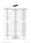
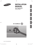
Wiring Work
Power and communication cable connection
1
Before wiring work, you must turn off all power source.
2
Indoor unit power should be supplied through the breaker(ELCB or MCCB+ELB) separated by the outdoor power.
ELCB: Earth Leakage Circuit Breaker
MCCB:Molded Case Circuit Breaker
ELB:Earth Leakage Breaker
3
The power cable should be used only copper wires.
4
Connect the power cable{1(L), 2(N)} among the units within maximum length and communication cable(F1, F2) each.
5
Connect V1, V2(for DC12V) and F3, F4(for communication) when installing the wired remote Control.
Outdoor Unit
Wired Remote
Control
220-240V~
or
ELCB
L
Indoor Unit 1
Indoor Unit 2
N
MCCB+
ELB
Indoor Unit 3
EEV kit
N
L
N
L
N
L
ELCB : Essential Installation
WARNING :
Power off before connecting any wires;
Indoor PBA will be damaged while V1,V2,F3,F4 short each other.
Indoor Unit 4 Indoor Unit 5 Indoor Unit 6
Ceiling, wall-mounted indoor unit.
Selecting compressed ring terminal
Silver solder
B
D
d1
E
F
L
d2
t
Norminal
Norminal
Standard
Standard
Standard
Standard
dimensions for dimensions for
Allowance
Allowance
Allowance
Allowance
Min. Min. Max. dimension
Min.
dimension
dimension
dimension
cable (mm2)
screw (mm)
(mm)
(mm)
(mm)
(mm)
(mm)
(mm)
(mm)
(mm)
1.5
2.5
4
4
4
4
4
6.6
8
6.6
8.5
4
9.5
±0.2
3.4
±0.2
4.2
±0.2
5.6
+0.3
-0.2
+0.3
-0.2
+0.3
-0.2
1.7
±0.2
4.1
6
16
4.3
2.3
±0.2
6
6
17.5
4.3
3.4
±0.2
6
5
20
4.3
+0.2
0
+0.2
0
+0.2
0
0.7
0.8
0.9
E-22
AVXC1@@_IM_E_29824-2_12.14.09.indd 22
2009-12-14 18:27:23
Specification of electronic wire
Power supply
MCCB
Max : 242V
Min : 198V
XA
Rating current
Communication
ELB or ELCB Power cable Earth cable
cable
Unit
Model
Rating current
AVXC1
022
028
036
0.18A
0.20A
0.23A
AVXCS
022
028
036
0.20A
0.23A
0.25A
The capacity of ELCB(or MCCB+ELB) X [A] = 1.25 X 1.1 X ∑Ai
AVXC2
056
071
0.38A
0.40A
X : The capacity of ELCB(or MCCB+ELB).
∑Ai : Sum of Rating currents of each indoor unit.
Refer to each installation manual about the rating current of indoor unit.
AVXC4E
045
056
071
090
112
128
140
0.19A
0.19A
0.21A
0.23A
0.23A
0.30A
0.36A
AVXC4EG
045
056
071
090
112
128
140
0.40A
0.40A
0.40A
0.50A
0.60A
0.60A
0.80A
AVXCM
028
036
056
071
0.50A
0.50A
0.52A
0.55A
X A, 30mmA
0.1 sec
2.5mm2
2.5mm2
0.75~1.5mm2
Decide the capacity of ELCB(or MCCB+ELB) by below formula.
Decide the power cable specification and maximum
length within 10% power drop among indoor units.
Coef×35.6×Lk×ik
n
∑(
1000×Ak
k=1
)<
10% of input
voltage[V]
Coef: 1.55
Lk : Distance among each indoor unit[m], Ak: Power cable specification[mm2]
ik : Running current of each unit[A]
Example of Installation
- Total power cable length L = 100(m), Running current of each units 1[A]
- Total 10 indoor units were installed
10[A]
9[A]
1[A]
ELCB
Or MCCB+
ELB
0[m]
Indoor unit10
Indoor unit2
Indoor unit1
10[m]
20[m]
100[m]
Apply following equation.
Coef×35.6×Lk×ik
n
∑(
1000×Ak
k=1
)<
10% of input
voltage[V]
Calculation
Installing
with 1 sort wire.
2.5[mm2]
2.5[mm2]
-2.2[V]
-2.0[V]
220[V]
208.8[V](Within 198V~242V)
it's okay
-(2.2+2.0+1.8+1.5+1.3+1.1+0.9+0.7+0.4+0.2)=-11.2[V]
Installing
with 2 different sort wire.
4.0[mm2]
220[V]
············ 2.5[mm2] ············
4.0[mm2]
-1.4[V]
············ 2.5[mm2] ············
-1.2[V]
-(1.4+1.2+1.8+1.5+1.3+1.1+0.9+0.7+0.4+0.2)=-10.5[V]
209.5[V](Within 198V~242V)
it's okay
E-23
AVXC1@@_IM_E_29824-2_12.14.09.indd 23
2009-12-14 17:39:33
Wiring Work (Continued)
CAUTION
Select the power cable in accordance with relevant local and national
regulations.
Wire size must comply with local and national code.
For the power cable, use the grade of H07RN-F or H05RN-F materials.
You should connect the power cable into the power cable terminal
and fasten it with a clamp.
The unbalanced power must be maintained within 10% of supply
rating among whole indoor units.
If the power is unbalanced greatly, it may shorten the life of the
condenser. If the unbalanced power is exceeded over 10% of supply
rating, the indoor unit is protected, stopped and the error mode
indicates.
To protect the product from water and possible shock, you should keep
the power cable and the connection cord of the indoor and outdoor
units in the iron pipe.
Connect the power cable to the auxiliary circuit breaker.
An all pole disconnection from the power supply must be incorporated
in the fixed wiring(≥3mm).
You must keep the cable in a protection tube.
Keep distances of 50mm or more between power cable and
communication cable.
Maximum length of power cables are decided within 10% of power
drop. If it exceeds, you must consider another power supplying
method.
The circuit breaker(ELCB or MCCB+ELB) should be considered more
capacity if many indoor units are connected from one breaker.
Use round pressure terminal for connections to the power terminal
block.
For wiring, use the designated power cable and connect it firmly,
then secure to prevent outside pressure being exerted on the terminal
board.
Use an appropriate screwdriver for tightening the terminal screws.
A screwdriver with a small head will strip the head and make proper
tightening impossible.
Over-tightening the terminal screws may break them.
See the table below for tightening torque for the terminal screws.
Tightening torque(kgf•cm)
M4
12.0~14.7
E-24
AVXC1@@_IM_E_29824-2_12.14.09.indd 24
2009-12-14 17:39:34
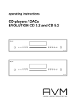
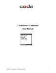
Indoor Unit Setting
1
Before installing the indoor unit, assign an address to the indoor unit
according to the air conditioning system plan.
2
The address of the indoor unit is assigned by adjusting MAIN(SW01, SW02) and
RMC(SW03, SW04) rotary switches.
SW01
SW02
K1 K2 K3 K4
SW03
K5 K6 K7 K8
SW04
K9K10K11K12
The designs and shape are subject to change according to the model.
Setting MAIN Address
The MAIN address is for communication between the indoor unit and the
outdoor unit. Therefore, you must set it to operate the air conditioner
properly.
You can set the MAIN address from ‘00’ to ‘99’ by mixing SW01 and SW02.
The MAIN address from ‘00’ to ‘99’ should differ from each other.
Check the indoor unit address on the plan that you are to install and set
the address according to the plan.
Note
You may not need to set MAIN address if you selected Auto
Address Setting from the outdoor unit: see details on the outdoor
unit installation manual.
For Example
When MAIN address is set as "12".
Setting RMC Address
You must set the SW03, SW04 and K2 switch when using the centralized controller.
For Example
When RMC address is set as "12".
SW03
SW04
E-25
AVXC1@@_IM_E_29824-2_12.14.09.indd 25
2009-12-14 17:39:34
Additional Functions
No.
SW05
K1 K2 K3 K4
Function
ON
OFF
K1
External room sensor
Not use
Use
K2
Centralized controller
Not use
Use
1way/Slim 1way/2way/
mini 4way
-
-
4way
Not use
Use
-
-
K3
Compensation RPM
K4
-
K1 OFF
Heating mode : Setting temperature compensation value = 0°C
Thermo OFF Fan OFF
No.
Function
K5
SW06
K5 K6 K7 K8
K9K10K11K12
OFF
1way/Slim 1way/2way
+2°C
+5°C
4way/mini 4way
+5°C
+2°C
K6
Filter Time
K7
-
-
-
K8
-
-
-
No.
SW07
Heating Current
Temperature
Compensation
ON
1000 hours 2000 hours
Function
ON
OFF
K9
Indoor Expansion Valve For
Heating Stop
Fix 80 step
0 or 80 step
K10
Wired Remocon Group Master
Not Use
Use
K11
External control
Not Use
Use
K12
Operation output
Thermal ON
Operation ON
E-26
AVXC1@@_IM_E_29824-2_12.14.09.indd 26
2009-12-22 8:38:53
Final Checks and User Tips
To complete the installation, perform the following checks and tests to ensure
that the air conditioner operates correctly.
1
Check the followings.
Strength of the installation site
Tightness of pipe connection to detect a gas leak
Electric wiring connections
Heat-resistant insulation of the pipe
Drainage
Earth conductor connection
Correct operation (follow the steps below)
After finishing the installation of the air conditioner, you should explain the
following to the user. Refer to appropriate pages in the User’s Manual.
1
How to start and stop the air conditioner
2
How to select the modes and functions
3
How to adjust the temperature and fan speed
4
How to adjust the airflow direction
5
How to set the timers
6
How to clean and replace the filters
Note
When you complete the installation successfully, hand over
the User’s Manual and this Installation Manual to the user for
storage in a handy and safe place.
E-27
AVXC1@@_IM_E_29824-2_12.14.09.indd 27
2009-12-14 17:39:36
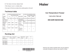
Troubleshooting
Detection of errors
If an error occurs during the operation, one or more LED flickers and the operation is stopped except the LED.
If you re-operate the air conditioner, it operates normally at first, then detect an error again.
LED Display on the receiver & display unit
LED Display
Indicators
Abnormal conditions
Operating
Green
Red
X
Power reset
Error of temperature sensor in indoor unit
(OPEN/SHORT)
X
Error of heat exchanger sensor in indoor unit
Error of heat exchanger OUT sensor in indoor unit
Error of outlet temperature sensor in indoor unit
(OPEN/SHORT): For heat pump models only
Error of indoor fan motor:
Below 450RPM for 15 minutes
X
X
X
X
Error of outdoor temperature sensor
Error of COND sensor
Error of DISCHARGE sensor
X
X
X
X
X
X
Displayed on appropriate indoor unit
which is operating
Displayed on appropriate indoor unit
which is operating
X
X
X
Displayed on appropriate indoor unit
which is operating
X
X
X
Displayed on appropriate indoor unit
which is operating
Displayed on outdoor unit
1. No communication for 2 minutes between
indoor unit and outdoor unit (communication
error for more than 2 minutes)
1. Error of indoor unit: Displayed on the
indoor unit regardless of operation
2. Indoor unit receiving the communication
error from outdoor unit
2. Error of outdoor unit: Displayed on the
indoor unit which is operating
3. Outdoor unit tracking 3 minute error
X
X
X
4. When sending the communication
error from outdoor unit due to the
mismatching of the communication
numbers and installed numbers after
completion of tracking (communication
error for more than 2 minutes)
On
Flickering
X Off
If you turn off the air conditioner when the LED is flickering, the LED is also turned off.
If you re-operate the air conditioner, it operates normally at first, then detects an error again.
E-28
AVXC1@@_IM_E_29824-2_12.14.09.indd 28
2009-12-14 17:39:36
LED Display
Indicators
Abnormal conditions
Operating
Green
Red
Self-diagnostic error
(including the indoor unit not detected)
1. Error of electronic expansion valve close
2. Error of electronic expansion valve open
X
X
Displayed on appropriate indoor unit
which is operating
Displayed on outdoor unit
X
3. Breakaway of EVA OUT sensor
4. Breakaway of EVA IN sensor
Displayed on appropriate indoor unit
which is operating
Displayed on outdoor unit
5. Breakaway of COND MID sensor
6. 2nd detection of refrigerant completely leak
7. 2nd detection of high temperature COND
8. 2nd detection of high temperature DISCHARGE
9. COMP DOWN due to 2nd detection of
low pressure switch
X
X
Detection of the float switch
X
X
Error of setting option switches for optional
accessories
X
X
10. Error of reverse phase
11. Compressor down due to 6th detection of
freezing
12. Self-diagnosis of condensation sensor (G8, G9)
13. Compressor down due to condensation
ratio control
X
EEPROM error
X
-
X
-
X
-
EEPROM option error
On
Flickering
-
X Off
If you turn off the air conditioner when the LED is flickering, the LED is also turned off.
If you re-operate the air conditioner, it operates normally at first, then detects an error again.
E-29
AVXC1@@_IM_E_29824-2_12.14.09.indd 29
2009-12-14 17:39:37
"EEE Yönetmeliğine Uygundur"
"This EEE is compliant with RoHS"
AVXC1@@_IM_E_29824-2_12.14.09.indd 30
2009-12-14 17:39:37
INSTALLATION
MANUAL
Cassette Type Series
1 way cassette : AVXC1
AVXCS(Slim)
2 way cassette : AVXC2
4 way cassette : AVXC4
AVXCM(mini)
Air Conditioner
E DB98-31753A(1)
AVXC1@@_IM_E_31753_12.14.09.indd 31
2009-12-25 14:15:05