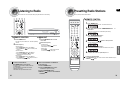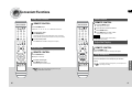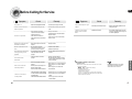
1
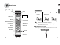
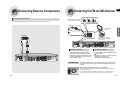
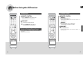
Digital Surround
AV Receiver System
HT-AS610
AV-R610
THIS APPLIANCE IS MANUFACTURED BY:
Instruction Manual
AH68-01853K
Safety Warnings
GB
Precautions
PREPARATION
This symbol indicates that dangerous voltage which
can cause electric shock is present inside this unit.
CAUTION
RISK OF ELECTRIC SHOCK.
DO NOT OPEN
This symbol alerts you to important operating and
maintenance instructions accompanying the unit.
CAUTION:
TO REDUCE THE RISK OF ELECTRIC SHOCK, DO
NOT REMOVE REAR COVER. NO USER
SERVICEABLE PARTS INSIDE. REFER SERVICING TO
QUALIFIED SERVICE PERSONNEL.
WARNING: To reduce the risk of fire or electric shock, do not
expose this appliance to rain or moisture.
CAUTION: TO PREVENT ELECTRIC SHOCK, MATCH WIDE
BLADE OF PLUG TO WIDE SLOT, FULLY INSERT.
VOLUME
Ensure that the AC power supply in your house complies with the identification sticker located on the back of your player. Install
your player horizontally, on a suitable base (furniture), with enough space around it for ventilation (7.5~10cm). Make sure the
ventilation slots are not covered. Do not stack anything on top of the player. Do not place the player on amplifiers or other
equipment which may become hot. Before moving the player, ensure the disc tray is empty. This player is designed for
continuous use. Switching off the DVD player to the stand-by mode does not disconnect the electrical supply. In order to
disconnect the player completely from the power supply, remove the main plug from the wall outlet, especially when left unused
for a long period of time.
• This apparatus shall always be connected to a AC outlet with a protective grounding connection.
• To disconnect the apparatus from the mains, the plug must be pulled out from the mains socket, therefore the mains
plug shall be readily operable.
EUROPE ONLY
This marking shown on the product or its literature, indicates that it should not
be disposed with other household wastes at the end of its working life.
To prevent possible harm to the environment or human health from uncontrolled
waste disposal, please separate this from other types of wastes and recycle it
responsibly to promote the sustainable reuse of material resources.
Household users should contact either the retailer where they purchased this
product, or their local government office, for details of where and how they
can take this item for environmentally safe recycling.
Business users should contact their supplier and check the terms and
conditions of the purchase contract.
This product should not be mixed with other commercial wastes for disposal.
2
During thunderstorms, disconnect AC main plug from
the wall outlet.
Voltage peaks due to lightning could damage the unit.
Do not expose the unit to direct sunlight or other heat
sources.
This could lead to overheating and malfunction of the
unit.
Protect the player from moisture(i.e. vases) , and excess
heat(e.g.fireplace) or equipment creating strong magnetic or
electric fields (i.e.speakers...). Disconnect the power cable from
the AC supply if the player malfunctions. Your player is not
intended for industrial use.
Use of this product is for personal use only.
Condensation may occur if your player or disc have been
stored in cold temperatures.
If transporting the player during the winter, wait approximately
2 hours until the unit has reached room temperature before using.
The battery used with this product contain chemicals
that are harmful to the environment.
Do not dispose of batteries in the general household
trash.
3
Features
GB
Contents
PREPARATION
PREPARATION
Digital AV Receiver
This product is a pure digital AV receiver that performs digital signal processing to minimize
signal distortion and loss.
Safety Warnings ..............................................................................................................2
Precautions......................................................................................................................3
Features ..........................................................................................................................4
Description ......................................................................................................................6
CONNECTIONS
Dolby Pro Logic II
Connecting the Speakers ................................................................................................10
Connecting External Components ..................................................................................12
Connecting the FM and AM Antennas.............................................................................15
Dolby Pro Logic II is a new form of multi-channel audio signal
decoding technology that improves upon existing Dolby Pro Logic.
OPERATION
DTS (Digital Theater Systems)
DTS play backs 5.1 channel sound with less compression than Dolby
Digital for richer sound.
Before Using the AV Receiver .........................................................................................16
Selecting Digital/Analog Input .........................................................................................18
Setting the Speaker Mode ...............................................................................................20
Setting the Speaker Listening Distance .........................................................................22
Setting Digital Input .........................................................................................................24
Setting DRC (Dynamic Range Compression) .................................................................25
Test Tone ........................................................................................................................26
Setting Speaker Level .....................................................................................................28
Dolby Pro Logic ll Mode..................................................................................................30
Dolby Pro Logic ll Effect .................................................................................................32
SFE Mode........................................................................................................................34
Stereo Mode ....................................................................................................................36
SFE(Sound Field Effect) Using 24bit Audio Digital Signal Processing
Provides more realistic surround sound with normal stereo audio sources.
RADIO OPERATION
Listening to Radio ...........................................................................................................38
Presetting Radio Stations ...............................................................................................39
MISCELLANEOUS
Convenient Functions......................................................................................................40
Operating your TV with the Remote Controll...................................................................42
Operating your VCR (DVD) with the Remote Control......................................................44
Before Calling for Service................................................................................................46
Specifications ..................................................................................................................48
4
5
GB
Description
FUNCTION button
SELECT ( , ) button
INPUT MODE button
TUNING ( , ) button
POWER STANDBY Indicator
HEADPHONE Jack
FM ANTENNA
JACK
SURROUND button
SETUP button
POWER button
VOLUME CONTROL
VCR/SAT VIDEO INPUT
JACK
VCR VIDEO OUTPUT
JACK
AM ANTENNA
JACK
DVD VIDEO INPUT
JACK
DVD OPTICAL DIGITAL AUDIO
INPUT JACK
CD COAXIAL DIGITAL
AUDIO INPUT JACK
FRONT SPEAKER
TERMINALS
MONITOR VIDEO
OUTPUT JACK
PREPARATION
[ Rear Panel ]
[ Front Panel ]
COOLING FAN
SUBWOOFER SPEAKER TERMINALS
SURROUND SPEAKER TERMINALS
CENTER SPEAKER TERMINALS
[ Display ]
DVD AUDIO INPUT JACKS
DTS
LIVE SURROUND
INDICATOR
INDICATOR
DOLBY
INDICATOR
VCR/SAT AUDIO INPUT JACKS
L.PCM
INDICATOR
SPEAKER INDICATOR
CD AUDIO INPUT JACKS
VCR AUDIO OUTPUT JACKS
SUBWOOFER OUTPUT JACKS 1, 2
DOLBY DIGITAL
INDICATOR
RADIO FREQUENCY
INDICATOR
√√ Accessories œœ
DIGITAL INDICATOR
DOLBY PRO
LOGIC II
INDICATOR
RADIO STEREO INDICATOR
Remote Control
AM Antenna
FM Antenna
User’s Manual
RADIO BROADCASTING
RECEIVING INDICATOR
FRONT DISPLAY
6
7
GB
Description
TV button
AMP button
Insert Remote Batteries
DVD button
VCR button
DIMMER button
POWER button
TV VIDEO, FUNCTION button
CD button
NUMBER(0~9) buttons
PREPARATION
[ Remote Control ]
1
Remove the battery
cover in the direction
of the arrow.
2
Insert two 1.5V AAA
batteries, paying
attention to the correct
polarities (+ and –).
3
Replace the battery
cover.
VCR/SAT button
DVD button
SLEEP button
MO/ST button
DRC button
TUNER button
INPUT MODE DIGITAL button
INPUT MODE ANALOG button
EXTERNAL DEVICE PLAYBACK button
MUTE button
VOLUME CONTROL button
MENU button
TUNER/CHANNEL button
TUNING MODE button
Follow these precautions to avoid leaking or cracking batteries:
• Place batteries in the remote control so they match the polarity:(+) to (+)and (–)to (–).
• Use the correct type of batteries.Batteries that look similar may differ in voltage.
• Always replace both batteries at the same time.
• Do not expose batteries to heat or flame.
Range of Operation of the Remote Control
The remote control can be used up to approximately 23 feet/7 meters in a straight line. It can also be operated
at a horizontal angle of up to 30° from the remote control sensor.
CURSOR/ENTER button
SUBWOOFER button
INFO button
STEREO button
SPK DISTANCE button
TUNER MEMORY button
MODE button
EFFECT button
TEST TONE button
SPK LEVEL button
SFE MODE button
8
SPK SELECT button
9
GB
Connecting the Speakers
Before moving or installing the product, be sure to turn off the power and disconnect the power cord.
ACTIVE SUBWOOFER
(not supplied)
FRONT (R)
PS-AF610
FRONT (L)
PS-AF610
SURROUND SURROUND (L)
PS-AR610
(R)
CONNECTIONS
• If more bass is desired, you can
connect an additional active
subwoofer (not supplied) to the
Subwoofer 1or 2 port. Since the
signal on the Subwoofer 1and 2 ports
is not stereo, you will hear the same
mono bass sound regardless of the
port you connect to.
MAIN UNIT
AV-R610
SL
SR
SYSTEM MODEL NAME : HT-AS610
Position of AV Receiver
Surround Speakers
• Place AV Receiver on a dedicated stand or rack.
• Place these speakers behind your listening position.
• If there isn't enough room, place these speakers so they
face each other.
• Place them about 60 to 90cm (2 to 3feet) above your ear,
facing slightly downward.
❈ Unlike the front and center speakers, the surround
speakers are used to handle mainly sound effects and
sound will not come from them all the time.
Front Speakers
• Place these speakers in front of your listening
position, facing inwards (about 45°) toward you.
• Place the speakers so that their tweeters will be at
the same height as your ear.
• Align the front face of the front speakers with the
front face of the center speaker or place them
slightly in front of the center speakers.
MAIN UNIT
FRONT SPEAKER
CENTER SPEAKER
SURROUND SPEAKER
PASSIVE SUBWOOFER
AV-R610
PS-AF610
PS-AC610
PS-AR610
PS-AW610
CENTER
PS-AC610
PASSIVE
SUBWOOFER
PS-AW610
√ Connecting Speaker Wire
1
Press the tab of the
speaker connector.
Subwoofer
2
Insert the black wire into the black(-)
terminal and the gray wire into the
red(+) terminal.
• The position of the subwoofer is not so critical.
Place it anywhere you like.
Center Speaker
• It is best to install it at the same height as the front
speakers.
• You can also install it directly over or under the TV.
• When you attach the speakers to a wall, make sure to
fasten them tightly so they do not fall off.
Caution
• Keep the subwoofer speaker out of reach of children to prevent them from inserting their hands or objects
into the duct (hole) of the subwoofer speaker.
• Never touch speaker terminals while the power is on.
Doing so could result in electric shock.
• Make sure the polarities (+ and -) are correct.
10
11
GB
Connecting External Components
Connecting Video Component
Before moving or installing the product, be sure to turn off the power and disconnect the power cord.
SAT(Settop Box)
or
Video Projector
• The Analog Audio and Video In jacks of the main unit
can be used for SAT or VCR.You cannot connect
both devices at the same time.
• If the external component has only one Audio Output
jack, connect it to either the right or left Audio Input
jack of the main unit.
• Connect the audio cable's red plug to the red jack
and white cable to the white jack.
or
• Disconnect the power plug from the outlet if you will not use this unit for a long period of time.
• Even though the Digital Audio inputs are labelled DVD and CD, you can connect your DVD/CD player to either
the OPTICAL or COAXIAL digital audio input (as long as it matches the Digital audio output on your player).
12
CONNECTIONS
DVD Player
TV
VCR
13
Connecting External Components
Connecting Audio Component
Before moving or installing the product, be sure to turn off the power and disconnect the power cord.
GB
Connecting the FM and AM Antennas
If AM reception is poor, connect an
outdoor AM antenna(not supplied).
CONNECTIONS
AM Loop Antenna
(supplied)
CD Player
FM Antenna (supplied)
Snap the tabs on the loop into the
slots of the base to assemble the
AM loop antenna.
FM antenna connection
1. Connect the FM antenna supplied to the FM
75ΩCOAXIAL terminal as a temporary measure.
2. Slowly move the antenna wire around until you find
a location where reception is good, then fasten it to
a wall or other rigid surface.
COOLING FAN
AM antenna connection
1. Connect the AM loop antenna supplied to the AM
and terminals.
2. If reception is poor, connect an outdoor single vinylcovered wire to the AM terminal.
(Keep the AM loop antenna connected).
The cooling fan dissipates the heat generated inside the unit so that the unit can
be operated normally. The cooling fan is activated automatically to supply cool air
to the unit.
Please observe the following cautions for your safety.
• Make sure the unit is well-ventilated. If the unit has poor ventilation, the temperature inside may
rise and cause damage to it.
• Do not obstruct the cooling fan or ventilation holes. (If the cooling fan or ventilation holes are
covered with a newspaper or cloth, heat may build up inside the unit and fire may result.)
14
15
GB
Before Using the AV Receiver
Turning On/Off
REMOTE CONTROL
Press the POWER button of the remote control.
• This unit will be turned on or set to Standby mode.
To Select a Function
REMOTE CONTROL
Method 1
Press the FUNCTION button.
• Each time you press the this button, FM ➝ AM ➝ DVD ➝ VCR/SAT ➝ CD
MAIN UNIT
1 Connect the power plug to the outlet.
2 Press the POWER button of the main unit.
will be selected in turn.
Method 2
Press CD, VCR/SAT, DVD or TUNER button.
• You can directly select CD, VCR/SAT, DVD or TUNER.
OPERATION
• This unit will be turned on or set to Standby mode.
MAIN UNIT
Functions of Dedicated Remote Control
Press FUNCTION button.
• Each time you press the this button, FM ➝ AM ➝ DVD ➝ VCR/SAT ➝ CD
will be selected in turn.
You can operate your AMP(this AV receiver), TV, DVD and VCR with this
remote control.
See pages 44-47 for more details.
16
17
GB
Selecting Digital/Analog Input
You can listen to sound in 2 Channel analog or Dolby Digital 5.1 Channel using this unit.
REMOTE CONTROL
For DVD Function
Follow steps 1-4 in DVD setup on page 26 before selecting the DVD Input Mode.
Press the INPUT MODE DIGITAL button.
• DVD OPTICAL or COAXIAL will be selected based on the DVD setup you made
on page 26
MAIN UNIT
or
Press the INPUT MODE ANALOG button.
For DVD Function
Follow steps 1-4 in DVD setup on page 26 before selecting the DVD Input Mode.
• DVD setup is not required before selecting the DVD Analog mode.
Press the INPUT MODE button.
OPERATION
• DVD ANALOG will be selected.
• DVD OPTICAL or COAXIAL and DVD ANALOG will be selected repetitively.
For CD Function
Follow steps 1-4 in CD setup on page 26 before selecting the CD Input Mode.
Press the INPUT MODE DIGITAL button.
• CD OPTICAL or COAXIAL will be selected based on the DVD setup you made
on page 26
For CD Function
Follow steps 1-4 in CD setup on page 26 before selecting the CD Input Mode.
Press the INPUT MODE button.
• CD OPTICAL or COAXIAL and CD ANALOG will be selected repetitively.
or
Press the INPUT MODE ANALOG button.
• CD ANALOG will be selected.
• CD setup is not required before selecting the CD Analog mode.
• The product is set to “DVD:OPTICAL,CD:COAXIAL ” by factory default.
• You can enjoy Dolby Digital only if you connect the Digital Audio Output jack
of an external audio component to the Optical/Coaxial Digital Audio Input jack
on the main unit.
18
19
GB
Setting the Speaker Mode
Before moving or installing the product, be sure to turn off the power and disconnect the power cord.
Frequency response from the speaker will be adjusted according to your speaker configuration and whether certain
speakers are used or not.
√
REMOTE CONTROL
SPK SELECT button to select the speaker you want.
1 Press
Each time you press this button, F.SPK ➝ C.SPK ➝ S.SPK ➝ SW SPK ➝
•
CROVR ➝ SPK MODE OFF will be selected in turn.
MAIN UNIT
2 Press …† button to set the mode (Large, Small etc.) for the
SETUP button.
1 Press
“SETUP MODE” appears on the display and enters into Setup Mode.
3 Repeat steps 1-2 to set the mode for each speaker.
2 Press FUNCTION button 1 time.
To Exit Setup Mode
3 Press SURROUND button to select the speaker you
selected speaker.
•
OPERATION
• “SPK SETUP” appears in the display.
want.
• Wait for about 5 seconds or press the SPK SELECT button of the remote control to
• Each time you press this button, F.SPK ➝ C.SPK ➝ S.SPK ➝ SW SPK ➝
select SPK MODE OFF.
CROVR will be selected in turn.
4 Press SELECT (
,
) button to set the mode for the
selected speaker.
5 Repeat steps 3-4 to adjust each speaker.
To Exit Setup Mode
• Wait for about 5 seconds or press SETUP button.
“SETUP MODE OFF” appears on the display and exits Setup Mode.
To turn the SUBWOOFER On or Off.
Press SUBWOOFER button on the remote.
• Each time you press this button, SW SPK : YES, SW SPK : NO will be selected in
turn.
• If F.SPK is set to LARGE, you can select YES or NO for SW SPK.
• If F.SPK is set to SMALL, SW SPK is automatically set to YES. NO cannot be
Setting the Speaker
SPEAKER
F.SPK(Front)
C.SPK(Center)
S.SPK(Surround)
SW SPK(Subwoofer)
CROVR
(Crossover Frequency)
Possible Settings
LARGE,SMALL
LARGE,SMALL,NONE
LARGE,SMALL,NONE
YES,NO
60,80,100,120,
150,180,200(Hz)
Default Setting
SMALL
SMALL
SMALL
YES
150Hz
• LARGE : Select when using large speakers. You can listen to full
range sound.
• SMALL : Select when using small speakers.
Bass below 100Hz will not be output.
• NONE : Select when you use no speaker.
• YES(Subwoofer) : Select when using the Subwoofer Speaker.
• NO(Subwoofer) : Select when not using the Subwoofer Speaker.
• CROVR: Select the crossover frequency for the best bass
response in your room.
selected.
20
21
GB
Setting the Speaker Listening Distance
√
REMOTE CONTROL
1 Press the SPK DISTANCE button to select the speaker you
want.
• Each time you press this button, F.L ➝ CEN ➝ F.R ➝ S.R ➝ S.L ➝ S.W
➝ DIST OFF will be selected in turn.
…† button to set the speaker distance.
2 Press
For F.L, CEN, F.R, S.W, S.R, S.L Speaker, you can set the distance from
•
the speaker to listening position between 0.3~9.0m in intervals of 0.3m.
MAIN UNIT
SETUP button.
1 Press
“SETUP MODE” appears on the display and enters into Setup Mode.
2 Press FUNCTION button 2 times.
•
To Exit Setup Mode
• Wait for about 5 seconds or press the SPK DISTANCE button of remote control to
SURROUND button to select the speaker you want.
3 Press
Each time you press this button, F.L ➝ CEN ➝ F.R ➝ S.R ➝ S.L ➝
•
S.W will be selected in turn.
select DIST OFF.
SELECT( , ) button to set the speaker distance.
4 Press
For F.L, CEN, F.R, S.W, S.R, S.L Speaker, you can set the distance from the
•
speaker to listening position between 0.3~9.0m in intervals of 0.3m.
To Exit Setup Mode
• Wait for about 5 seconds or press SETUP button.
“SETUP MODE OFF” appears on the display and Setup Mode is exited.
• If the listening position is beyond the range of speaker distance setup when
you place the speaker, set the speaker distance to the maximum.
22
23
OPERATION
• “DIST SETUP” appears on the display.
Digital Input Setup
Setting DRC (Dynamic Range Compression)
You must set the digital input for a DVD or CD player to either Optical or Coaxial depending on which Digital
input you have your player connected to.
You can use this function to enjoy Dolby Digital sound when watching movies at low volume at night.
GB
√
MAIN UNIT
REMOTE CONTROL
DVD SETUP
•
• “DIGITAL IN” appears on the display.
3 Press SURROUND button to select DVD.
4 Press SELECT( , ) button to set the digital input.
• Each time you press this button, OPTICAL
COAXIAL will be selected in turn.
• Each time you press this button, DRC : STD ➝ DRC : MAX ➝ DRC : MIN
will be selected in turn.
MAIN UNIT
SETUP button.
1 Press
“SETUP MODE” appears on the display and enters into Setup Mode.
2 Press FUNCTION button 4 times.
•
• “DRC SETUP” appears on the display.
To Exit Setup Mode
• Wait for about 5 seconds or press SETUP button.
“SETUP MODE OFF” appears on the display and the unit exits Setup Mode.
CD SETUP
SETUP button.
1 Press
“SETUP MODE” appears on the display and enters into Setup Mode.
2 Press FUNCTION button 3 times.
•
• “DIGITAL IN” appears on the display.
3 Press SURROUND button to select CD.
4 Press SELECT( , ) button to set the digital input.
• Each time you press this button, OPTICAL
Press DRC button.
OPERATION
1 “SETUP MODE” appears on the display and enters into Setup Mode.
2 Press FUNCTION button 3 times.
Press SETUP button.
SURROUND button.
3 Press
“DRC : STD” appears on the display .
4 Press SELECT( , ) button to set DRC.
•
• Each time you press this button, DRC : STD ➝ DRC : MAX ➝ DRC : MIN
will be selected in turn.
To Exit Setup Mode
• Wait for about 5 seconds or press SETUP button.
“SETUP MODE OFF” appears on the display and the unit exits Setup Mode.
COAXIAL will be selected in turn.
To Exit Setup Mode
• Wait for about 5 seconds or press SETUP button.
“SETUP MODE OFF” appears on the display and the unit exits Setup Mode.
Setting DRC
24
• STD : Sets DRC effect to standard.
• MAX : Sets DRC effect to maximum.
• MIN : Sets DRC effect to minimum.
25
GB
Test Tone
Use test tone to check the speaker connection status or level.
To Automatically Output Test Tone
√
REMOTE CONTROL
Press TEST TONE button.
• Test signal will be automatically output as follows; F.L ➝ CEN ➝ F.R ➝ S.R
To Manually Output Test Tone
➝ S.L ➝ S.W.
• During test tone output, press …† button to adjust the speaker output level
from -10 to +10 dB by 1 step.
• Press TEST TONE button again.
OPERATION
√
To Stop Test Tone
MAIN UNIT
√
SETUP button.
1 Press
“SETUP MODE” appears on the display and the unit enters into Setup Mode.
2 Press FUNCTION button 6 times.
•
MAIN UNIT
SETUP button.
1 Press
“SETUP MODE” appears on the display and enters into Setup Mode.
2 Press FUNCTION button 5 times.
“TEST-T AUTO” appears in the display.
3 Press SURROUND button.
• “TEST-T MANU” appears in the display.
3 Press SURROUND button.
•
• Each time you press this button, F.L ➝ CEN ➝ F.R ➝ S.R ➝ S.L ➝ S.W will
be selected in turn.
•
4 Press SELECT(
• You can adjust the speaker output level from -10 to +10dB by 1 step.
• The sound gets quieter at -10dB and louder at +10dB.
S.R ➝ S.L ➝ S.W .
,
) button to set the test tone as you
want.
• Test signal will be automatically output as follows; F.L ➝ CEN ➝ F.R ➝
• During test signal output, press SELECT (
,
) button to adjust the speaker
output level from -10 to +10 dB by 1 step.
To Stop Test Tone
To Stop Test Tone
Press SETUP button 1 time.
• “SETUP MODE OFF” appears on the display and test signal stops.
Press SETUP button 1 time.
• “SETUP MODE OFF” appears on the display and test tone stops.
Test Tone Output
26
• F.L (Front-Left) : -10 ~ +10dB
• CEN (Center) : -10 ~ +10dB
• F.R (Front-Right) : -10 ~ +10dB
• S.R (Surround-Right) : -10 ~ +10dB
• S.L (Surround-Left): -10 ~ +10dB
• S.W (Subwoofer): -10 ~ +10dB
27
GB
Setting Speaker Level
You can set the balance and level of speakers
√
Remote Control
SPK LEVEL button to select the speaker you want.
1 Press
Each time you press this button, F.L ➝ CEN ➝ F.R ➝ S.R ➝ S.L ➝ S.W ➝
•
MAIN UNIT
SPK LVL OFF will be selected in turn.
…† button to set the speaker level you want.
2 Press
You can adjust it from -10 to +10dB by 1 step.
•
•
The sound gets quieter at -10dB and louder at +10dB.
Default setting value is 00dB.
•
1 Press SETUP button.
• “SETUP MODE” appears on the display and enters into Setup Mode.
OPERATION
FUNCTION button 8 times.
2 Press
“LEVEL SETUP” appears on the display.
•
3 Press SURROUND button.
To Exit Setup Mode
• Wait for about 5 seconds or press SPK LEVEL button on the remote control to select
• Each time you press this button, F.L ➝ CEN ➝ F.R ➝ S.R ➝ S.L ➝ S.W
SPK LVL OFF.
will be selected in turn.
4 Press SELECT(
,
) button to set to the speaker level you
want.
• You can adjust it from -10 to +10dB by 1 step.
• The sound gets smaller at -10dB and louder at +10dB.
• Default setting value is 00dB
To Exit Setup Mode
• Wait for about 5 seconds or press SETUP button.
“SETUP MODE OFF” appears on the display and exits Setup Menu.
Setting Speaker Level
• F.L (Front-Left) : -10 ~ +10dB
• CEN (Center) : -10 ~ +10dB
• F.R (Front-Right) : -10 ~ +10dB
• S.R (Surround-Right) : -10 ~ +10dB
• S.L (Surround-Left): -10 ~ +10dB
• S.W (Subwoofer): -10 ~ +10dB
28
29
GB
Dolby Pro Logic ll Mode
This mode provides 5.1 channel sound from 2 channel sources
REMOTE CONTROL
Press
MODE button.
• Each time you press this button, CINEMA ➝ MATRIX ➝ GAME
➝ PROLOGIC ➝ MUSIC will be selected in turn.
MAIN UNIT
1 Press SURROUND button to select “DPL ll”
Mode.
• Each time you press this button, DPL ll ➝ SFE ➝ STEREO will be selected
in turn.
,
OPERATION
2 Press SELECT(
) button.
) button, CINEMA ➝ MATRIX ➝
GAME ➝ PROLOGIC ➝ MUSIC will be selected in turn.
• Each time you press SELECT (
) button, MUSIC ➝ PROLOGIC ➝
GAME ➝ MATRIX ➝ CINEMA will be selected in turn.
• Each time you press SELECT (
To Exit Setup Mode
To Exit Setup Mode
• Wait for about 5 seconds.
• Wait for about 5 seconds.
Dolby Pro Logic ll Mode
• MUSIC : Provides 5.1 Channel Surround sound to digital, analog
or existing stereo sources such as CD, TAPE, FM, TV and Stereo
VCR.
• CINEMA : Adds realism to the movie soundtrack.
• MATRIX : You will hear 5.1 Channel Surround sound.
• GAME : Enhances the excitement of the game's sound.
• PROLOGIC : You will experience a surround effect with just the
front left and right speakers.
30
• You cannot use Dolby Pro Logic ll Mode for multi channel
signals such as Dolby Digital and DTS.
• Pro Logic works only for PCM audio signals with sampling
frequencies of 32KHz,44KHz or 48KHz.
31
GB
Dolby Pro Logic ll Effect
This function works only in Dolby PRO LOGIC II MUSIC Mode.
REMOTE CONTROL
MODE button to select ‘MUSIC’ Mode.
1 Press
EFFECT button.
2 Press
Each time you press this button, C-WIDTH ➝ DIMENSION ➝ PANORAMA
•
will be selected in turn.
MAIN UNIT
SETUP button.
1 Press
“SETUP MODE” appears on the display and enters into Setup Mode.
•
OPERATION
FUNCTION button 10 times.
2 Press
“DPL ll MODE”appears on the display.
•
SURROUND button.
3 Press
Each time you press this button, C-WIDTH ➝ DIMENSION ➝
Press …† button to select Dolby Pro Logic II effect you
3 want.
•
PANORAMA will be selected in turn.
• C-WIDTH: You can set from 0 to 7.
• DIMENSION: You can set from -7 to +7.
• PANORAMA: You can Set it ON or OFF.
4 Press SELECT(
,
) button to select Dolby Pro Logic ll
effect you want.
To Exit Setup Mode
• Wait for about 5 seconds.
To Exit Setup Mode
• Wait for about 5 seconds or press SETUP button.
“SETUP MODE OFF” appears on the display and exits Setup Mode.
Dolby Pro Logic ll Effect
• C-WIDTH : This sets the width of the center image. The higher the setting, the less
sound comes from the center speaker.
• DIMENSION : Incrementally adjusts the sound field (DSP)from the front or rear.
• PANORAMA : This mode extends the front stereo image to include the surround
speakers for an exciting "wraparound" effect with side wall imaging.
32
33
GB
SFE Mode
The SFE (Sound Field Effect) function uses 7 different DSP sound field effects to digitally simulate
actual music environments such as concert halls or movie theaters.
REMOTE CONTROL
Press SFE MODE button.
• Each time you press this button, HALL ➝ THEATER ➝ ARENA ➝ CLUB ➝
DOME ➝ STADIUM ➝ CHURCH will be selected in turn.
MAIN UNIT
SURROUND button to select ‘SFE’ Mode.
1 Press
Each time you press this button, DPL II ➝ SFE ➝ STEREO will be selected
•
in turn.
,
) button.
) button, HALL ➝ THEATER ➝ ARENA ➝
CLUB ➝ DOME ➝ STADIUM ➝ CHURCH will be selected in turn
• Each time you press Select (
) button, CHURCH ➝ STADIUM ➝ DOME
➝ CLUB ➝ ARENA ➝ THEATER ➝ HALL will be selected in turn.
• Each time you press Select (
To Exit Setup Mode
• Wait for about 5 seconds.
To Exit Setup Mode
• Wait for about 5 seconds.
34
35
OPERATION
2 Press SELECT(
GB
Stereo Mode
You can select this mode when listening to sound through the Front Left and Right speakers and subwoofer.
For Surround Mode and Input Signal
o = active, – = inactive
Output Channel
Surround Mode
DOLBY
(MUSIC,
CINEMA,
MATRIX,
GAME,
PROLOGIC)
Display Information
Input Signal
Decoding
L/R
C
Dolby D Surr. EX
Dolby Digital 5.1
O
O
O
O
DIGITAL
L, C, R, SL, SR, SW
Dolby D (5.1ch)
Dolby Digital 5.1
O
O
O
O
DIGITAL
L, C, R, SL, SR, SW
Dolby D (2ch)
Pro Logic II
O
O
O
O
DIGITAL
L, C, R, SL, SR, SW
Dolby D (2ch Surr)
Pro Logic II
O
O
O
O
DIGITAL
L, C, R, SL, SR, SW
L.PCM (Audio)
Pro Logic II
O
O
O
O
L.PCM
L, C, R, SL, SR, SW
Analog
Pro Logic II
O
O
O
O
ANALOG
L, C, R, SL, SR, SW
DTS-ES
DTS 5.1
O
O
O
O
DTS
L, C, R, SL, SR, SW
DTS 96/24
DTS 5.1
O
O
O
O
DTS
L, C, R, SL, SR, SW
DTS (5.1)
DTS 5.1
O
O
O
O
DTS
L, C, R, SL, SR, SW
L.PCM (Audio)
Neo:6
O
O
O
-
L.PCM
L, R
O
O
O
DIGITAL
L, C, R, SL, SR, SW
DIGITAL
L, C, R, SL, SR, SW
SL
Sub
SR Woofer
Display Signal Format
Channel Status
DTS
MAIN UNIT
Press STEREO button.
Press SURROUND button to select ‘STEREO’. •
Dolby D (2ch)
DD + SFE
O
• “STEREO” appears in the display and Stereo Mode is
Each time you press this button, DPL ll ➝ SFE ➝ STEREO
will be selected in turn.
Dolby D (2ch Surr)
DD + SFE
O
O
O
O
L.PCM (Audio)
SFE
O
O
O
O
L.PCM
L, C, R, SL, SR, SW
Analog
SFE
O
O
O
O
ANALOG
L, C, R, SL, SR, SW
Dolby D (2ch)
DD
O
-
-
-
DIGITAL
L, R, SW
Dolby D (2ch Surr)
DD
O
-
-
-
DIGITAL
L, R, SW
L.PCM (Audio)
Stereo
O
-
-
-
L.PCM
L, R, SW
To Exit Setup Mode
L.PCM 96KHz
Stereo
O
-
-
-
L.PCM
L, R, SW
• Wait for about 5 seconds.
Analog
Stereo
O
-
-
-
ANALOG
L, R, SW
selected.
SFE
To Exit Setup Mode
• Wait for about 5 seconds.
OPERATION
REMOTE CONTROL
STEREO
L/R : Front Speaker (Left/Right) C : Center Speaker SL/SR : Rear Speaker (Left/Right) SW : Subwoofer
• When PCM and Analog Stereo signals are input, the left and right channels are played back
in Stereo Mode.
36
• Channel status displays are dependent on the speaker configuration.
• SFE Mode works with 2ch signals.
37
Listening to Radio
Presetting Radio Stations
You can listen to the chosen band (FM, AM) by using either automatic or manual tuning.
You can preset up to 30 FM and AM stations.
GB
REMOTE CONTROL
Ex) Setting station FM 89.10 in preset 2 .
TUNER button.
1 Press
Each time you press this button, FM ➝ AM will be selected in turn.
•
2 Press Select button and then TUNING MODE button
to
select 89.10.
• Refer to step 2, page 38, to tune in automatically and manually.
REMOTE CONTROL
MAIN UNIT
1 Press TUNER button.
1 Press FUNCTION button to select
• Each time you press this button, FM ➝ AM will be repetitively
selected.
2 Select frequency.
:
1) Press TUNING MODE button to select PRESET.
2) Press TUNING/CH ( , ) button to select the preset
frequency.
• Automatic Tuning 2 :
1) Press TUNING MODE button to select MANUAL
2) Press and hold TUNING/CH ( , ) button to
automatically tune in frequency.
• Manual Tuning :
1) Press TUNING MODE button to select MANUAL.
2) Press TUNING/CH ( , ) button briefly to increase or
decrease the frequency step by step.
To Listen to Mono/Stereo
Press MO/ST button on the remote.
• Each time you press this button, STEREO, MONO will
be selected in turn.
• If you select MONO in the area with weak reception,
it will help to reduce noise.
• This function works only with the Remote Control.
38
2 Select the frequency.
•
4 Press TUNING/CH(
, ) button to select preset 2.
• You can select from presets 1 to 30.
• Automatic Tuning :
Press and hold TUNING( , ) button to
automatically tune in frequency.
• Manual Tuning :
Press TUNING( , ) button briefly to increase
or decrease the frequency step by step.
TUNER MEMORY button.
5 Press
Tuner number will disappear and station 89.10 will be saved in preset 2.
RADIO OPERATION
• Automatic Tuning 1
FM or AM.
TUNER MEMORY button.
3 Press
Tuner number will blink on the display.
•
6 To preset other stations, repeat steps 2 to 5.
To Listen to Preset Station
• Press TUNING MODE button of the remote control to select the PRESET and press
TUNING/CH (
,
) button.
How to select PRESET and MANUAL
on the main unit.
1. Press the SETUP button.
2. Press the FUNCTION button 9 times.
• “TUNER SETUP” appears in the display.
3. Press the SURROUND button.
4. SELECT ( , ) button to select MANUAL
or PRESET.
39
GB
Convenient Functions
Sleep Timer Function
You can set the time that this unit will shut itself off.
REMOTE CONTROL
Press the SLEEP button.
• SLEEP : OFF ➝ 15 ➝ 30 ➝ 45 ➝ 60 ➝ 90 ➝ 120MIN will be selected in turn.
To Check Sleep Timer
Press SLEEP button.
• The remaining time before this unit will shut itself off is shown on the display.
• Pressing the button again changes the sleep time from what you set previously.
To Cancel Sleep Timer
• Press SLEEP button until SLEEP : OFF appears on the display.
Reset Function
REMOTE CONTROL
the MUTE button.
1 Press
MUTE appears on the display.
“0” button five times and then
2 Press
press ENTER button.
…† buttons to select “YES”.
3 Press
The unit will turn off after 5 seconds.
•
•
Caution
• Using the RESET function will erase all stored settings.
• Do not use this unless necessary.
Adjust the Display
You can adjust the brightness of the display.
Mute Function
This function is useful when answering a doorbell or telephone call.
REMOTE CONTROL
Press the MUTE button.
• MUTE appears on the display.
Press MUTE button again.
• MUTE will disappear and sound will output.
Press the DIMMER button.
• Each time you press this, the brightness of the display will be adjusted.
Using Headphone
Use headphones (not supplied) for private listening pleasure.
Connect the headphone to the headphone jack and listen
to music.
MISCELLANENOUS
To Output Sound Again
REMOTE CONTROL
• Do not turn the volume up too high when you use headphones as It
may damage your hearing.
• SLEEP, Mute and the Adjust Display function can only be
operated with the remote control.
40
41
GB
Operating your TV with the Remote Control
TV Brand Code List
1
2
3
4
Brand
Press TV button to set the remote
to TV mode.
Press POWER button to turn
on the TV.
Point the remote control toward the TV.
While holding down POWER button,
enter the code corresponding to your
brand of TV.
• If the code matches the TV's code, the TV will be turned off.
• If there is more than one code listed for your TV in the table, enter
one at a time to determine which code works.
• You can use the TV POWER, VOLUME, CHANNEL, MENU and
Numeric buttons (0~9).
AOC
BELL & HOWELL(M.WARDS)
BROCSONIC
CANDLE
CETRONIC
CITIZEN
CINEMA
CLASSIC
CONCERTO
CONTEC
CORONADO
CRAIG
CROSLEX
CROWN
CURTIS MATHES
CXC
DAEWOO
DAYTRON
DYNASTY
EMERSON
FISHER
FUNAI
FUTURETECH
GENERAL ELECTRIC(GE)
HALL MARK
HITACHI
INKEL
JC PENNY
JVC
KTV
KEC
KMC
LG(GOLDSTAR)
Code Number
056, 057, 058
001, 015
001, 002, 003, 004,005,
006, 007, 008, 009, 010,
011, 012, 013, 014
001, 018, 040, 048
057, 058, 081
059, 060
018
003
003, 018, 025
097
003
018
046
015
003, 005, 061, 082, 083,
084
062
003
059, 061, 063
003
002, 003, 004, 015,016,
017, 018, 019, 020, 021,
022, 023, 024, 025, 026,
027, 028, 029, 030, 032,
034, 035, 036, 040, 048,
059, 090, 099, 100
040
003
003, 015, 040, 046, 059,
061, 064, 082, 083, 084,
085
019, 065, 103
003
003
006, 040, 056, 059, 066,
067, 068
040
015, 018, 050, 059, 069
045
056, 059, 067, 086
070
059, 061, 087, 088
003, 015, 040
015
001, 015, 016, 017, 037,
038, 039, 040, 041, 042,
043, 044, 054, 086
Brand
LUXMAN
LXI(SEARS)
MAGNAVOX
MARANTZ
MATSUI
MGA
MITSUBISHI/MGA
MTC
NEC
NIKEI
ONKING
ONWA
PANASONIC
PENNEY
PHILCO
PHILIPS
PIONEER
PORTLAND
PROTON
QUASAR
RADIO SHACK
RCA/PROSCAN
REALISTIC
SAMPO
SAMSUNG
SANYO
SCOTT
SEARS
SHARP
SIGNATURE 2000 (M.WARDS)
SONY
SOUNDESIGN
SPECTRICON
SSS
Code Number
018
019, 054, 056, 059, 060,
062, 063, 065, 071
015, 017, 018, 048, 054,
059, 060, 062, 072, 089
040, 054
054
018, 040
018, 040, 054, 059, 060,
075, 101
018
018, 019, 020, 040, 059,
060
003
003
003
006, 007, 008, 009, 054,
066, 067, 073, 074
018
003, 015, 017, 018, 048,
054, 059, 062, 069, 090
015, 017, 018, 040, 048
054, 062, 072, 112, 114,
117, 118
063, 066, 080, 091
015, 018, 059
040
006, 066, 067
017, 048, 056, 060, 061,
075
018, 059, 067, 076, 077
078, 092, 093, 094
003, 019
040
000, 015, 016, 017, 040,
043, 046, 047, 048, 049,
054, 059, 060, 098
019, 061, 065, 101, 102,
103, 104
003, 040, 060, 061
015, 018, 019
015, 057, 064, 101, 105,
106, 115
057, 058
050, 051, 052, 053, 055,
101
003, 040
001
018
Brand
SYLVANIA
SYMPHONIC
TATUNG
TECHWOOD
TEKNIKA
TMK
TOSHIBA
VIDTECH
VIDECH
WARDS
YAMAHA
YORK
YUPITERU
ZENITH
ZONDA
DONGYANG
LOWE
FINLUX
YOKO
LOEWE OPTA
PHONOLA
RADIOLA
SCHNEIDER
AKAI
GRUNDIG
BLAUPUNKT
SIEMENS
CGE
IMPERIAL
MIVAR
SABA
BANG&OLUFSEN
BRIONVEGA
FORMENTI
METZ
WEGA
RADIOMARELLI
SINGER
SINUDYNE
TELEFUNKEN
Code Number
018, 040, 048, 054, 059,
060, 062
061, 095, 096
006
018
003, 015, 018, 025
018, 040
019, 057, 063, 071, 101
107, 109, 110, 111, 113
018
059, 060, 069
015, 017, 018, 040, 048,
054, 060, 064
018
040
003
058, 079
001
003, 054
054
054, 109, 114
054
054, 114
054, 112, 114
054, 112
054
103
108, 109, 113, 119, 120,
121
108
108
113
113
113
114
114
114
114
114
114
114
114
114
116
MISCELLANENOUS
5
If TV is turned on or off when you press the
power button of the remote control, the
setting is completed.
ADMIRAL(M.WARDS)
A MARK
ANAM
• The remote control may not work on some brands of TVs. Also, some operations
may not be possible depending on your brand of TV.
• The remote control will work with Samsung TVs by default.
42
43
GB
Operating your DVD (VCR) with Remote Control
VCR Brand Code List
Brand
1
2
3
4
Press DVD button to set the remote to DVD
mode.
• If you operate VCR, press VCR button to set the remote to VCR mode.
Press POWER button to turn on the DVD
(VCR).
Point the remote control toward the DVD
(VCR).
While holding down POWER button, enter
the code corresponding to your brand of
DVD (VCR).
• If the code matches the DVD (VCR)'s code, the DVD (VCR)
will be turned off.
• If there is more than one code listed for your DVD (VCR) in
the table, enter one at a time to determine which code works.
• You can use DVD (VCR) POWER, VOLUME, PLAY, PAUSE,
STOP, SKIP, MENU and Numeric button (0~9).
AOC
AUDIO DYNAMIC
BELL & HOWELL(M.WARDS)
BROKSONIC
CANON
CAPEHART
CITIZEN
CRAIG
CRITERION
CURTIS MATHES
DAEWOO
DAYTRON
DBX
EMERSON
FISHER
FUNAI
GENERAL ELECTRIC(GE)
GO VIDEO
HARMAN KARDON
HITACHI
HQ
INSTANT REPLAY
JCL
JCP
JC PENNY
JVC
KENWOOD
LG(GOLDSTAR)
LXI(SEARS)
MAGIN
MAGNAVOX
• The remote control may not work on some brands of DVD (VCR).
Also, some operations may not be possible depending on your brand
of DVD (VCR).
• The remote control will work with Samsung DVDs (VCRs) by default.
44
MARANTZ
MARTA
Code Number
043, 106
044, 045, 046
088, 089, 090
001, 002, 003, 004, 005,
033
091
019, 047, 092
048, 093
092, 094, 095
001, 033, 049, 091
011
050
050, 072, 096
051
001, 031, 032, 033, 044,
091
006, 007, 008, 009, 010,
011, 012, 013, 014, 015,
016, 017, 018, 046, 051,
091
011
019, 047, 052, 092
025, 031, 032, 044, 046,
094, 095, 097, 098, 099
009, 048, 053, 054, 055,
100
044
001, 031, 032, 033, 056,
091
059, 060, 061
019
020, 021, 049, 054, 062,
100
051
001, 033, 049, 091
001, 033
025
047, 048, 052, 062, 091,
092
001, 033, 047, 052, 063,
064, 065, 092
047, 050, 052, 092
019, 020, 021, 022, 023,
024, 025, 026, 027, 028,
029, 030, 050
020, 025, 044, 048, 050,
053, 054, 055, 062, 100
072
001, 031, 032, 033, 049,
066, 067, 091
001, 019, 033, 047, 052,
092, 110
025, 050
Brand
MEI
MEMOREX
MINOLTA
MITSUBISHI/MGA
MTC
MULTITECH
NEC
OLYMPIC
OPTIMUS
ORION
PANASONIC
PENNEY
PENTAX
PHILCO
PHILIPS
PILOT
PIONEER
PORTLAND
QUASAR
RICO
RCA/PROSCAN
REALISTIC
SAMSUNG
SANYO
SANSUI
SCOTT
SEARS
SHARP
SINGER
SIGNATURE 2000 (M.WARDS)
SHINTOM
SONY
STS
SYLVANIA
SYMPHONIC
TANDY
Code Number
001, 033
001, 025, 033, 054, 091,
100
020, 021, 062
068, 069, 070, 101, 102
072
044, 057, 069
019, 047, 052, 057, 092
049, 091
101
103
001, 004, 033, 049, 067,
091, 107
019, 020, 072
001, 020, 021, 033, 062
001, 033, 046, 049, 091,
094
001, 030, 033, 049, 050,
066, 091
025
049
011
001, 033, 049, 067, 091,
107, 108
036
001, 020, 021, 031, 032,
033, 049, 051, 062, 066,
070, 091, 104
001, 009, 025, 033,
044, 048, 054, 091,
101, 105
000, 006, 031, 032, 057,
058, 071, 072, 073, 074,
075, 076, 077, 078, 079,
080, 081
008, 009, 046, 048, 050,
054, 058, 093, 100
092
006, 051, 054, 057, 069,
070, 100, 101
020, 021, 025
043, 105, 106
096
043, 044, 054, 100, 106
096
034, 035, 036, 037, 038,
039, 040, 041, 042,082,
083, 084, 085, 086
020
001, 033, 044, 049, 066,
091
044
009
Brand
TASHIRO
TATUNG
TEAC
TECHNICS
TEKNIKA
TOSHIBA
TOTEVISION
TAEKWANG
UNITECH
VECTOR RESEARCH
VIDEO CONCEPTS
VIDEOSONIC
WARDS
YAMAHA
ZENITH
Code Number
050
047, 052, 092
044, 047, 052, 092
001, 033, 049, 091
001, 025, 033
006, 051
025, 072
087
072
019
019
072
001, 020, 031, 032, 033,
043, 050, 054, 072, 100,
105, 106, 109
019, 047,048, 052, 092,
019, 047,048, 052, 092
DVD Brand Code List
Brand
DENON
DOONOON
DMTECH
FISHER
GE
HARMAN/KARDON
JVC
KENWOOD
LG
MAGNAVOX
MITSUBISHI
ONKYO
OPTIMUS
PANASONIC
PROSCAN
PHILIPS
PIONEER
RCA
SAMSUNG
SANYO
SONY
THETA DIGITAL
TOSHIBA
YAMAHA
ZENITH
TAEGWANG
PS2
X-BOX
APEX
MARANTZ
Code Number
003, 032
019
017
002
006
012
010, 013
008
001
004
005, 016
004, 014
011
021
006
004, 023
007, 011, 022, 025
006
000, 027
002
015, 020
011
004, 018
009, 033
004, 024
026
028
029
030
031
MISCELLANENOUS
5
If DVD (VCR) is turned on or off when you
press the power button of the remote
controller, the setting is completed.
ADMIRAL(M.WARDS)
AWIA
AKAI
ANAM
45
GB
Before Calling for Service
Check
Symptom
Can't turn it on.
It does not work when the
button is pressed.
• Is the power code plugged into the outlet?
• Is there static electricity in the air?
Sound is not produced.
components connected properly?
• Is the Mute function on?
• Is the volume set to minimum?
• Is the speaker setup set incorrectly to
NONE?
Picture does not appear when
the function is selected.
• Is the external component connected
Remote controller does not
work.
• Are the batteries drained?
• Is the distance between remote
The sound from each device
is changed during stereo
playback.
Can't receive radio
properly?
control and main unit proper?
• Are the left/right speaker or left/right
input/output cables connected
properly?
• Is AM or FM antenna connected
properly?
properly?
• Is S.SPK (Surround) incorrectly set to
NONE in Speaker Setup?
• Is Surround Mode selected to Stereo?
There is no sound from
center speaker
• Properly connect them.
• Press Mute button to cancel the function.
There is no sound when
playing a DTS encoded
DVD.
• Select 2 channel Dolby Digital, PCM, and
Analog input signal.
• Is Digital input selected?
• Check whether digital external component
is properly connected and refer to page 22
to select the digital input.
• Refer to pages 22~23 to select LARGE,
SMALL or YES.
• Properly connect it.
• Replace with new batteries.
• Operate at close distance.
• Check the left/right channel and properly
connect it.
• Properly connect the antenna.
• If the input strength of antenna connector
• Refer to pages 10~11 to connect it properly.
• Refer to pages 20~21 to select LARGE or
SMALL.
• Refer to pages 30~37 to select other
Surround Mode.
• Refer to pages 10~11 to connect it properly.
• Is C.SPK (Center) incorrectly set to NONE
• Refer to pages 20~21 to select LARGE or
• Is the Surround Mode selected to Stereo?
• Is the input signal selected properly?
ll Mode.
Remedy
• Adjust the volume.
• Is the center speaker connected properly?
in Speaker Setup?
Can't select Dolby Pro Logic
Check
SMALL.
MISCELLANENOUS
• Is the surround speaker connected
surround speakers.
• Disconnect the power plug and connect it
is weak, install the FM antenna in a place
with good reception.
broadcasts.
There is no sound from
• Connect the power plug to the outlet.
again.
• Are the speakers and external
Symptom
Remedy
Product Protection Function
Heat Protection
• The Protection function will come on if the main unit or power
transformer overheats.
"
" will appear in the display .
• If PROTECTION appears on the display,
check whether the speaker terminal is
shorted and then turn on the unit
This function will come on:
- If speaker terminal is shorted
- If speaker cable is shorted
If there is no problem when you turn the unit on again after
turning it off, “PROTECTION” will disappear from the display
and the unit will work properly.
• Refer to pages 30~37 to select other
Surround Modes.
46
47
GB
Specifications
Speaker system
GENERAL
FM TUNER
AM TUNER
AMPLIFIER
VIDEO
OUTPUT
0.9 W
Power Consumption
95 W
Weight
4.2 kg
Dimensions (W x H x D)
430 x 66 x 348 mm
Operating Temperature Range
+5 °C~+35 °C
Operating Humidity Range
10 %~75 %
Frequency Response
87.5~108.0 MHz
Usable Sensitivity
12 dBf
S/N Ratio
MONO/STEREO 55/55 dB
Distortion
MONO/STEREO 0.3/0.8 %
Stereo Separation
30 dB
Tuner Output Level
1 KHz, 75 KHz Dev
Frequency Response
522~1611 KHz
S/N Ratio
40 dB
Usable Sensitivity
60 dBµV/m(Loop Antenna)
Distortion
2 % (MOD:80 %)
Rated Output
20 Hz~20 KHz/THD = 10 %
Front Speaker(Left+Right)
4 Ω 100 W/CH
Center Speaker
4 Ω 100 W/CH
Surround Speaker(Left+Right)
4 Ω 100W/CH
Subwoofer Speaker
4 Ω 100W/CH
Input Sensitivity/Impedance
450 mV/47 kΩ
S/N Ratio(Analog Input)
80 dB
Separation(1KHz)
60 dB
Analog Input
20 Hz~20 KHz(±3 dB)
Digital Input
20 Hz ~44 KHz(±3 dB)
TV Format
NTSC/PAL
Input Level/Impedance
1 Vp-p/75 Ω
Output Level/Impedance
1 Vp-p/75 Ω
Video Frequency Response
5 Hz to 10 KHz(-3 dB)
Component Video Frequency Response
5 Hz to 40 KHz(-3 dB)
S/N Ratio
60 dB
S
P
E
A
K
E
R
S
Front / Surround
Center
Subwoofer speaker
Impedance
4Ωx4
4Ω
4Ω
Rated output
100 W
100 W
100 W
Maximum output
200 W
200 W
200 W
90 x 152 x 90 mm
200 x 90 x 92 mm
0.58 Kg/0.51 Kg
0.64 Kg
Dimensions (W x H x D)
Weight
175 x 320 x 381 mm
5 Kg
MISCELLANEOUS
FREQUENCY
RESPONSE
Standby Power Consumption
❈ S/N ratio, distortion, separation and usable sensitivity are based on measurement using AES (Audio Engineering Society) guidelines.
48
49
50