1
This product is not manufactured for Iran. SVC Warraty will not be
applicable and the user will be responsible for service
expenses when the product is used in Iran.
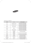
QUESTIONS OR COMMENTS?
COUNTRY
ALGERIA
IRAN
CALL
08000-7267864
16580
021 36 11 00
021-8255 [CE]
SAUDI ARABIA
8002474357
PAKISTAN
TUNISIA
U.A.E
OMAN
KUWAIT
BAHRAIN
QATAR
TURKEY
0800-Samsung (72678) 80-1000-12 800-SAMSUNG (800 - 726 7864)
800-SAMSUNG (800 - 726 7864)
183-CALL (183-2255)
8000-GSAM (8000-4726)
800-CALL (800-2255)
444 77 11
0800-22273
06 5777444
EGYPT
JORDAN
SYRIA
18252273
MOROCCO
SOUTH AFRICA
BOTSWANA
NAMIBIA
ZAMBIA
MAURITIUS
REUNION
MOZAMBIQUE
NIGERIA
080 100 22 55
0860 SAMSUNG (726 7864)
8007260000
08 197 267 864
0211 350370
23052574020
262508869
847267864 / 827267864
0800-726-7864
0800-10077
0302-200077
8000 0077
800-00-0077
7095-0077
0800 545 545
0800 300 300
0800 755 755 / 0685 889 900
9999
200
499999
1969
Ghana
Cote D’Ivoire
SENEGAL
CAMEROON
KENYA
UGANDA
TANZANIA
RWANDA
BURUNDI
DRC
SUDAN
PAC_아프리카 중동향AP80S0A_IBIM_34514A-02_EN.indd 56
OR VISIT US ONLINE AT
www.samsung.com/eg/support
www.samsung.com/n_africa/support
www.samsung.com/iran/support
www.samsung.com/sa/support
www.samsung.com/sa_en/support (English)
www.samsung.com/pk/support
www.samsung.com/n_africa/support
www.samsung.com/ae/support (English)
www.samsung.com/ae_ar/support (Arabic)
www.samsung.com/tr/support
www.samsung.com/Levant/support
(English)
www.samsung.com/Levant/support
(English)
www.samsung.com/n_africa/support
www.samsung.com/support
www.samsung.com/africa_en/support
www.samsung.com/africa_fr/support
www.samsung.com/support
2015-04-23 오후 2:19:01
AP80S0A Series
AP0AS0A Series
Air Conditioner
user & installation manual
imagine the possibilities
Thank you for purchasing this Samsung product.
EN ES FR PT AR DB98-34514A-02
PAC_아프리카 중동향AP80S0A_IBIM_34514A-02_EN.indd 57
2015-04-23 오후 2:19:01
Features of your new air conditioner
Highly sensual and fine quality design
Neat and elegant style allows it to be placed naturally anywhere within your interior.
Compact remote controller
Remote controller is compact enough to fit it your hand for easier use.
Triple safety system
Triple safety system provides high reliability and outstanding durability.
Contents
USING PARTS
Safety precautions . . . . . . . . . . . . . . . . . . . . . . . . . . . . . . . . . . . . . . . . . . . . . . . . . . . . . . . . . . . . . . . . . . . . . . . . . . . . . . . . . . . . . . . . . . . . . . . . . . . . . . . 3
Checking before use . . . . . . . . . . . . . . . . . . . . . . . . . . . . . . . . . . . . . . . . . . . . . . . . . . . . . . . . . . . . . . . . . . . . . . . . . . . . . . . . . . . . . . . . . . . . . . . . . . . . . . 7
Viewing the parts . . . . . . . . . . . . . . . . . . . . . . . . . . . . . . . . . . . . . . . . . . . . . . . . . . . . . . . . . . . . . . . . . . . . . . . . . . . . . . . . . . . . . . . . . . . . . . . . . . . . . . . . 8
Locking the control panel . . . . . . . . . . . . . . . . . . . . . . . . . . . . . . . . . . . . . . . . . . . . . . . . . . . . . . . . . . . . . . . . . . . . . . . . . . . . . . . . . . . . . . . . . . . . . . . . 9
Using the air conditioner with the control panel . . . . . . . . . . . . . . . . . . . . . . . . . . . . . . . . . . . . . . . . . . . . . . . . . . . . . . . . . . . . . . . . . . . . . . . . 10
Checking the remote controller . . . . . . . . . . . . . . . . . . . . . . . . . . . . . . . . . . . . . . . . . . . . . . . . . . . . . . . . . . . . . . . . . . . . . . . . . . . . . . . . . . . . . . . . . 11
Basic operation . . . . . . . . . . . . . . . . . . . . . . . . . . . . . . . . . . . . . . . . . . . . . . . . . . . . . . . . . . . . . . . . . . . . . . . . . . . . . . . . . . . . . . . . . . . . . . . . . . . . . . . . . 12
Adjusting the air flow direction . . . . . . . . . . . . . . . . . . . . . . . . . . . . . . . . . . . . . . . . . . . . . . . . . . . . . . . . . . . . . . . . . . . . . . . . . . . . . . . . . . . . . . . . . 14
Turbo operation . . . . . . . . . . . . . . . . . . . . . . . . . . . . . . . . . . . . . . . . . . . . . . . . . . . . . . . . . . . . . . . . . . . . . . . . . . . . . . . . . . . . . . . . . . . . . . . . . . . . . . . . 14
Smart saver operation . . . . . . . . . . . . . . . . . . . . . . . . . . . . . . . . . . . . . . . . . . . . . . . . . . . . . . . . . . . . . . . . . . . . . . . . . . . . . . . . . . . . . . . . . . . . . . . . . . 15
Timer function . . . . . . . . . . . . . . . . . . . . . . . . . . . . . . . . . . . . . . . . . . . . . . . . . . . . . . . . . . . . . . . . . . . . . . . . . . . . . . . . . . . . . . . . . . . . . . . . . . . . . . . . . 15
Cleaning and maintaining the air conditioner . . . . . . . . . . . . . . . . . . . . . . . . . . . . . . . . . . . . . . . . . . . . . . . . . . . . . . . . . . . . . . . . . . . . . . . . . . . 16
Troubleshooting . . . . . . . . . . . . . . . . . . . . . . . . . . . . . . . . . . . . . . . . . . . . . . . . . . . . . . . . . . . . . . . . . . . . . . . . . . . . . . . . . . . . . . . . . . . . . . . . . . . . . . . 19
INSTALLATION PARTS
Safety precautions . . . . . . . . . . . . . . . . . . . . . . . . . . . . . . . . . . . . . . . . . . . . . . . . . . . . . . . . . . . . . . . . . . . . . . . . . . . . . . . . . . . . . . . . . . . . . . . . . . . . . 21
Preparation for installation . . . . . . . . . . . . . . . . . . . . . . . . . . . . . . . . . . . . . . . . . . . . . . . . . . . . . . . . . . . . . . . . . . . . . . . . . . . . . . . . . . . . . . . . . . . . . 23
Deciding on where to install the product . . . . . . . . . . . . . . . . . . . . . . . . . . . . . . . . . . . . . . . . . . . . . . . . . . . . . . . . . . . . . . . . . . . . . . . . . . . . . . . 24
Preparing the installation . . . . . . . . . . . . . . . . . . . . . . . . . . . . . . . . . . . . . . . . . . . . . . . . . . . . . . . . . . . . . . . . . . . . . . . . . . . . . . . . . . . . . . . . . . . . . . . 30
Base construction and installation of the indoor · outdoor unit . . . . . . . . . . . . . . . . . . . . . . . . . . . . . . . . . . . . . . . . . . . . . . . . . . . . . . . . . . 31
Refrigerant piping work . . . . . . . . . . . . . . . . . . . . . . . . . . . . . . . . . . . . . . . . . . . . . . . . . . . . . . . . . . . . . . . . . . . . . . . . . . . . . . . . . . . . . . . . . . . . . . . . 33
Wiring work . . . . . . . . . . . . . . . . . . . . . . . . . . . . . . . . . . . . . . . . . . . . . . . . . . . . . . . . . . . . . . . . . . . . . . . . . . . . . . . . . . . . . . . . . . . . . . . . . . . . . . . . . . . . 40
Gas leak test and vacuum drying . . . . . . . . . . . . . . . . . . . . . . . . . . . . . . . . . . . . . . . . . . . . . . . . . . . . . . . . . . . . . . . . . . . . . . . . . . . . . . . . . . . . . . . 47
Refrigerant charging . . . . . . . . . . . . . . . . . . . . . . . . . . . . . . . . . . . . . . . . . . . . . . . . . . . . . . . . . . . . . . . . . . . . . . . . . . . . . . . . . . . . . . . . . . . . . . . . . . . 48
Setting the option switches & function keys . . . . . . . . . . . . . . . . . . . . . . . . . . . . . . . . . . . . . . . . . . . . . . . . . . . . . . . . . . . . . . . . . . . . . . . . . . . . 49
Check lists after completing the installation . . . . . . . . . . . . . . . . . . . . . . . . . . . . . . . . . . . . . . . . . . . . . . . . . . . . . . . . . . . . . . . . . . . . . . . . . . . . . 51
Trial operation . . . . . . . . . . . . . . . . . . . . . . . . . . . . . . . . . . . . . . . . . . . . . . . . . . . . . . . . . . . . . . . . . . . . . . . . . . . . . . . . . . . . . . . . . . . . . . . . . . . . . . . . . . 52
Error diagnosis . . . . . . . . . . . . . . . . . . . . . . . . . . . . . . . . . . . . . . . . . . . . . . . . . . . . . . . . . . . . . . . . . . . . . . . . . . . . . . . . . . . . . . . . . . . . . . . . . . . . . . . . . 53
How to connect your extended power cables . . . . . . . . . . . . . . . . . . . . . . . . . . . . . . . . . . . . . . . . . . . . . . . . . . . . . . . . . . . . . . . . . . . . . . . . . . 54
2
PAC_아프리카 중동향AP80S0A_IBIM_34514A-02_EN.indd 2
2015-04-23 오후 2:18:52
USING PARTS
Safety precautions
These warning signs are here to prevent injury to you and others. Please follow them carefully.
Important safety symbols and precautions :
Hazards or unsafe practices that may result in severe personal injury or death.
CAUTION
Hazards or unsafe practices that may result in minor personal injury or property damage.
ENGLISH
WARNING
Follow directions.
Do NOT attempt.
Make sure the machine is grounded to prevent electric shock.
Unplug the power plug from the wall socket.
Do NOT disassemble.
FOR INSTALLATION
WARNING
Plug the power cord into a wall socket with the power specifications of the product or higher and use the socket
for this appliance only. In addition, do not use an extension cord.
XXExtending the power cord may result in electric shock or fire.
XXDo not use an electric transformer. It may result in electric shock or fire.
XXIf the voltage/frequency/rated current condition is different, it may cause fire.
The installation of this appliance must be performed by a qualified technician or service company.
XXFailing to do so may result in electric shock, fire, explosion, problems with the product, or injury.
Install a switch and circuit breaker dedicated to the air conditioner.
XXFailing to do so may result in electric shock or fire.
Fix the outdoor unit firmly so that the electric part of the outdoor unit is not exposed.
XXFailing to do so may result in electric shock or fire.
Do not install this appliance near a heater, inflammable material. Do not install this appliance in a humid, oily or
dusty location, in a location exposed to direct sunlight and water (rain drops). Do not install this appliance in a
location where gas may leak.
XXThis may result in electric shock or fire.
Never install the outdoor unit in a location such as on a high external wall where it could fall.
XXIf the outdoor unit falls, it may result in injury, death or property damage.
This appliance must be properly grounded. Do not ground the appliance to a gas pipe, plastic water pipe, or
telephone line.
XXFailing to do so may result in electric shock, fire, and explosion, or other problems with the product.
XXNever plug the power cord into a socket that is not grounded correctly and make sure that it is in accordance with
local and national codes.
3
PAC_아프리카 중동향AP80S0A_IBIM_34514A-02_EN.indd 3
2015-04-23 오후 2:18:52
Safety precautions
FOR INSTALLATION
CAUTION
Install your appliance on a level and hard floor that can support its weight
XXFailing to do so may result in abnormal vibrations, noise, or problems with the product.
When installing the outdoor unit on the street, make sure to install it on the place with height over 2m or on the
place where warm air from the outdoor unit does not blow directly to the pedestrian.
XXThis is a policy on the architectural standards and it must be followed.
Install the draining hose properly so that water is drained correctly.
XXFailing to do so may result in water overflowing and property damage.
When installing, remove the wooden palette used for product transport.
XXWhen there is fire, this may cause spread of fire.
FOR POWER SUPPLY
WARNING
When the circuit breaker is damaged, contact your nearest service center.
Do not pull or excessively bend the power line. Do not twist or tie the power line. Do not hook the power line
over a metal object, place a heavy object on the power line, insert the power line between objects, or push the
power line into the space behind the appliance.
XXThis may result in electric shock or fire.
FOR POWER SUPPLY
CAUTION
When not using the air conditioner for a long period of time or during a thunder/lightning storm, cut the power
at the circuit breaker.
XXFailing to do so may result in electric shock or fire.
FOR USING
WARNING
If the appliance is flooded, please contact your nearest service center.
If the appliance generates a strange noise, a burning smell or smoke, unplug the power plug immediately and
contact your nearest service center.
XXFailing to do so may result in electric shock or fire.
In the event of a gas leak (such as propane gas, LP gas, etc.), ventilate immediately without touching the power
line. Do not touch the appliance or power line.
XXDo not use a ventilating fan.
XXA spark may result in an explosion or fire.
To reinstall the air conditioner, please contact your nearest service center.
XXFailing to do so may result in problems with the product, water leakage, electric shock, or fire.
XXA delivery service for the product is not provided. If you reinstall the product in another location, additional
construction expenses and an installation fee will be charged.
XXEspecially, when you wish to install the product in an unusual location such as in an industrial area or near the
seaside where it is exposed to the salt in the air, please contact your nearest service center.
4
PAC_아프리카 중동향AP80S0A_IBIM_34514A-02_EN.indd 4
2015-04-23 오후 2:18:52
FOR USING
ENGLISH
Do not touch the power plug or the circuit breaker with wet hands.
XXThis may result in electric shock.
Do not strike or pull the air conditioner with excessive force.
XXThis may result in fire, injury, or problems with the product.
Do not place an object near the outdoor unit that allows children to climb onto the machine.
XXThis may result in children seriously injuring themselves.
Do not turn the air conditioner off with the circuit breaker while it is operating.
XXTurning the air conditioner off and then on again with the circuit breaker may cause a spark and result in electric
shock or fire.
After unpacking the air conditioner, keep all packaging materials well out of the reach of children, as packaging
materials can be dangerous to children.
XXIf a child places a bag over his/her head, it may result in suffocation.
Do not insert your fingers or foreign substances into the outlet when the air conditioner is operating.
XXTake special care that children do not injure themselves by inserting their fingers into the product.
Do not insert your fingers or foreign substances into the air inlet/outlet of the air conditioner.
XXTake special care that children do not injure themselves by inserting their fingers into the product.
Do not use this air conditioner for long periods of time in badly ventilated locations or near infirm people.
XXSince this may be dangerous due to a lack of oxygen, open a window at least once an hour.
If any foreign substance such as water has entered the appliance, cut the power by unplugging the power plug
and turning the circuit breaker off and then contact your nearest service center.
XXFailing to do so may result in electric shock or fire.
Do not attempt to repair, disassemble, or modify the appliance yourself.
XXDo not use any fuse (such as cooper, steel wire, etc.) other than the standard fuse.
XXFailing to do so may result in electric shock, fire, problems with the product, or injury.
CAUTION
Do not place objects or devices under the indoor unit.
XXWater dripping from the indoor unit may result in fire or property damage.
Check that the installation frame of the outdoor unit is not broken at least once a year.
XXFailing to do so may result in injury, death or property damage.
Max current is measured according to IEC standard for safety and current is measured according to ISO standard
for energy efficiency.
Do not stand on top of the appliance or place objects (such as laundry, lighted candles, lighted cigarettes,
dishes, chemicals, metal objects, etc.) on the appliance.
XXThis may result in electric shock, fire, problems with the product, or injury.
Do not operate the appliance with wet hands.
XXThis may result in electric shock.
5
PAC_아프리카 중동향AP80S0A_IBIM_34514A-02_EN.indd 5
2015-04-23 오후 2:18:52
Safety precautions
Do not spray volatile material such as insecticide onto the surface of the appliance.
XXAs well as being harmful to humans, it may also result in electric shock, fire or problems with the product.
Do not drink the water from the air conditioner.
XXThe water may be harmful to humans.
Do not apply a strong impact to the remote controller and do not disassemble the remote controller.
Do not touch the pipes connected with the product.
XXThis may result in burns or injury.
Do not use this air conditioner to preserve precision equipment, food, animals, plants or cosmetics, or for any
other unusual purposes.
XXThis may result in property damage.
Avoid directly exposing humans, animals or plants from the air flow from the air conditioner for long periods of
time.
XXThis may result in harm to humans, animals or plants.
This appliance is not intended for use by persons (including children) with reduced physical, sensory or mental
capabilities, or lack of experience and knowledge, unless they have been given supervision or instruction
concerning use of the appliance by a person responsible for their safety. Children should be supervised to
ensure that they do not play with the appliance.
FOR CLEANING
WARNING
Do not clean the appliance by spraying water directly onto it. Do not use benzene, thinner or alcohol to clean
the appliance.
XXThis may result in discoloration, deformation, damage, electric shock or fire.
Before cleaning or performing maintenance, unplug the air conditioner from the wall socket and wait until the
fan stops.
XXFailing to do so may result in electric shock or fire.
FOR CLEANING
CAUTION
Take care when cleaning the surface of the heat exchanger of the outdoor unit since it has sharp edges.
XXTo avoid cutting your fingers, wear thick cotton gloves when cleaning it.
Do not clean the inside of the air conditioner by yourself.
XXFor cleaning inside the appliance, contact your nearest service center.
XXWhen cleaning the internal filter, refer to the descriptions in the "Cleaning and maintaining the air conditioner"
section.
XXFailure to do may result in damage, electric shock or fire.
6
PAC_아프리카 중동향AP80S0A_IBIM_34514A-02_EN.indd 6
2015-04-23 오후 2:18:52
Checking before use
Using outdoor unit
Take away any covers or barriers.
ffIt may cause product failure and poor performance in cooling by blocking air flow.
ENGLISH
Checking the auxiliary power switch
Turn on the auxiliary power switch which is installed separately.
NOTE
Auxiliary power switch (ELCB : Earth Leakage Circuit Breaker)
• Auxiliary power switch is not included in the package. Purchase and install it separately.
• Auxiliary power switch is a device for preventing over-current or short circuit. When not using the auxiliary power
switch for a long time, it should be turned off.
• If ELB have already been installed in the switch box of the building, you don’t need to install the auxiliary power
switch.
Operational temperature and humidity range
When the air conditioner operates outside of temperature and humidity range indicated below, protective device may
activate and stop the operation. Especially, do not operate the air conditioner when the temperature of the outdoor is below
-15°C since product can be damaged.
Mode
Indoor temperature
Outdoor temperature
Indoor humidity
Cool
21°C~32°C
21°C~52°C
Relative humidity 80% or less
Dry
21°C~32°C
21°C~52°C
-
ffIf the air conditioner operates in cooling mode for long period of time in high humidity area, dew may be formed.
7
PAC_아프리카 중동향AP80S0A_IBIM_34514A-02_EN.indd 7
2015-04-23 오후 2:18:53
Viewing the parts
The picture and function of the indoor unit may different depending on the model.
Main parts
Air flow blade (right/left orientation)
Air flow blade (up/down orientation)
Control panel
Air outlet
Air filter
Removes the dust of incoming air
Air intake
Intakes the outdoor air
To open the panel
Hold the upper part of the panel, and then pull it slightly forward. Don’t open the panel during the operation. It may cause a
malfunction or an electrical hazard.
8
PAC_아프리카 중동향AP80S0A_IBIM_34514A-02_EN.indd 8
2015-04-23 오후 2:18:53
Control panel and the display
Remote controller receiver
Receives and inputs the command
from the remote controller
Operation indicator
Displays the temperature, fan speed
and operation mode
ENGLISH
Turbo button
Temperature , button
Mode button
On/Off button
Fan Speed button
Locking the control panel
Whether the air conditioner is switched on or off, you cannot control the air conditioner with the control panel if this function
is set.
Press the Temp and Fan Speed buttons for 3 seconds.
ffYou will hear ring and the Lock icon will appear on the indoor unit display.
ffOnce Lock is set, you cannot control the air conditioner with the control panel but
you can only control it with the remote controller. Therefore this function will be
useful to keep the children away from touching the control panel.
ffTo unlock the control panel, press the Temp and Fan Speed buttons again for 3
seconds.
9
PAC_아프리카 중동향AP80S0A_IBIM_34514A-02_EN.indd 9
2015-04-23 오후 2:18:53
Using the air conditioner with the control panel
You can control the air conditioner without the remote controller.
1. Press the On/Off button on the indoor unit control panel.
ffThe air conditioner will operate in Cool mode.
Stop To turn off the air conditioner, press the On/Off button again.
2. Press the Temp and button to adjust the temperature.
ffYou can increase/decrease the temperature by 1°C.
3. Press the Fan Speed button to adjust the fan speed.
ffEach time you press the Fan Speed button, the fan speed will change in order of
(High) (Auto) (Low).
4. Press the Mode button to select the operation mode.
ffYou can select operation mode you want by pressing the Mode button.
ffEach time you press the Mode button, the mode will change in order of Cool, Auto,
Dry and Fan.
5. Press the Turbo button to select Turbo mode
NOTE
• General and duct type air conditioners may show different Fan speeds.
10
PAC_아프리카 중동향AP80S0A_IBIM_34514A-02_EN.indd 10
2015-04-23 오후 2:18:53
Checking the remote controller
The functions may be different depending on the model.
ffYou can activate the air conditioner by pointing the remote controller away from it. When using the remote controller,
always point it directly at the air conditioner.
ffWhen you press the button, a short ring will sound.
ENGLISH
Remote controller button
Smart Saver
Keep the indoor air cool while saving the
electricity.
Turbo/Long
Turbo – Set quick and powerful cooling.
Long – Set the long function to spread out
the cool air further away.
(Not supported by this model)
Temperature
Adjusts the temperature.
Timer
Sets the timer to turn off the air conditioner
Power
Turn on/off the air conditioner. Turn on/off
the air conditioner.
Mode
Set one of the 4 operation modes.
Beep Off
Turn off the beep sound.
(Not supported by this model)
Fan ▲, ▼
Adjusts the fan speed.
Air swing (Up/Down)
Activate/Deactivate air flow blade movement
automatically up and down.
(Not supported by this model)
Air swing (Left/Right)
Activate/Deactivate air flow blade movement
automatically right and left.
(Not supported by this model)
NOTE
• Long, Heater, Beep Off, Air swing(Up/Down, Left/Right) functions are not supported by this model.
Installing the batteries
1. Open the battery cover.
ffGently press the part on the battery cover and push it in the direction of the arrow.
2. Insert two AAA batteries.
ffCheck and match the “+” and “-“ signs accordingly.
3. Close the cover.
ffYou should hear click sound when the cover is locked properly.
CAUTION
NOTE
• Be careful not to get the remote controller wet.
• The signal may not be received well of electronic lighting style fluorescent lampssuch as inverter fluorescent lamps
are in the same space.
• If other electrical products operate by the remote controller, call your nearest contact center.
11
PAC_아프리카 중동향AP80S0A_IBIM_34514A-02_EN.indd 11
2015-04-23 오후 2:18:53
Basic operation
Basic operation is the operation mode that can be selected by pressing the Mode button.
Cool
In Cool mode, indoor temperature and fan speed can be adjusted at your desire to cool your indoor room.
Auto
When setting the desired temperature of the air conditioner for your fresh environment, the operation mode will operate
automatically according to the desired temperature and current temperature and control the fan speed in Auto mode.
Dry
In Dry mode, indoor humidity can be removed efficiently to refresh the humid indoor room.
ffSwitching the outdoor unit on or off will be repeated according to the temperature difference between current
temperature and the desired temperature.
Fan
In Fan mode, the breeze will be generated just like the electric fan to provide natural indoor environment.
12
PAC_아프리카 중동향AP80S0A_IBIM_34514A-02_EN.indd 12
2015-04-23 오후 2:18:53
Press the
button to start the operation of the air conditioner.
Press the
button to start the operation of the air conditioner.
ENGLISH
ffYou can check the display on the indoor unit to make sure that you selected desired operation mode.
Press the
button to start the operation of the air conditioner.
Cool
Auto
Dry
Fan
Press the
General type: (High), (Auto), (Low)
Duct type: (Turbo), (Auto), (High)
(Auto)
(Auto)
General type: (Low), (High)
Duct type: (High), (Turbo)
button to adjust the desired temperature.
Cool
You can adjust the desired temperature by 1°C within the range of 18°C~30°C.
Auto
When desired temperature is adjusted, operation mode will change to Cool mode.
Dry
You can adjust the desired temperature by 1°C within the range of 18°C~30°C.
Fan
Desired temperature cannot be adjusted.
13
PAC_아프리카 중동향AP80S0A_IBIM_34514A-02_EN.indd 13
2015-04-23 오후 2:18:54
Adjusting the air flow direction
Air flow can be directed to your desired position.
Hold the Air flow blade (up/down orientation) and adjust the up/down direction.
Hold the Air flow blade (left/right orientation) and adjust the left/right direction.
Turbo operation
Turbo operation function provides you with quick and powerful cooling.
Press the
button to select the Turbo operation.
ff
will be displayed on the indoor unit display and the Turbo
operation will operate for 30 minutes.
Cancel Press the Turbo/Long button again.
NOTE
• Turbo operation can be selected in Auto, Cool mode.
• Turbo operation and Smart saver operation cannot be selected at the same time.
• Desired temperature and fan speed cannot be adjusted.
14
PAC_아프리카 중동향AP80S0A_IBIM_34514A-02_EN.indd 14
2015-04-23 오후 2:18:54
Smart saver operation
Smart saver operation reduces your power consumption and save money on your electric bill.
Press the
button to select the Smart saver operation.
NOTE
ENGLISH
ff
will be displayed on the indoor unit display and the Smart saver
operation will begin.
Cancel Press the Smart Saver button again.
• Smart saver operation can be selected in Cool mode only.
• When Smart saver operation is activated, temperature range will be limited to 18°C~30°C.
• Temperature/Fan speed can also be adjusted.
• Smart saver operation and Turbo operation cannot be selected at the same time.
Timer function
You can turn the air conditioner off at your desired time.
Press the
button when the air conditioner is on.
ff icon will be displayed on the indoor unit display.
ffTime will be set in hourly unit from 1~12hours.
ffCurrent temperature will be displayed after 5 seconds.
ffIf you want to cancel the Timer function, press the Timer button until
you set the time to 12 hours and press it one more time. icon and the
set time will disappear.
NOTE
• Timer function can be set only when the air conditioner is on.
15
PAC_아프리카 중동향AP80S0A_IBIM_34514A-02_EN.indd 15
2015-04-23 오후 2:18:55
Cleaning and maintaining the air conditioner
CAUTION
• Make sure to turn off the auxiliary power switch or unplug the power plug when cleaning the air conditioner.
Cleaning the indoor unit
ffWipe the surface of the unit with a slightly wet or dry cloth when needed.
ffBrush away the dust on the narrow gap of air conditioner.
NOTE
CAUTION
• If it is difficult to clean the indoor unit heat exchanger on your own, contact
service center.
• Depending on the usage environment(restaurant, hair salon etc.), odor may be
generated. Prevent the odor by cleaning the air filter or performing Fan mode
while ventilating your room. If you have a problem with the odor, contact a
service center.
• Do not clean the control panel with alkaline detergent.
• Do not clean the surface with sulfuric acid, hydrochloric acid or organic solvent
(thinner, kerosene, acetone) or attach stickers. It may damage the surface of the
unit.
Cleaning the outdoor unit heat exchanger
ffWhen dust accumulates on the heat exchanger, it may decrease cooling performance.
Therefore, clean it regularly.
ffSpray water to clean the dust.
NOTE
CAUTION
• If it is too difficult to clean the outdoor unit heat exchanger on your own, contact
service center.
• Be careful with the sharp edges on the outdoor unit heat exchanger.
Heat exchanger
(Illustration may differ slightly
depending on the models.)
16
PAC_아프리카 중동향AP80S0A_IBIM_34514A-02_EN.indd 16
2015-04-23 오후 2:18:55
Cleaning the air filter
Washable air filter captures large particles from the air. The filter can be cleaned with a vacuum or by hand washing.
1. Open the panel and pull out the air filter.
ffPull out the air filter in the direction of the arrow as shown in the below figure.
ENGLISH
2. Clean the air filter with a vacuum cleaner or in running water.
ffIf dust is too heavy, use warm water mixed with detergent. Do not scrub the filter too hard since it may get damaged.
3. Dry the air filter in a ventilated area.
ffDo not dry the air filter in a place with direct sunlight.
4. Insert the air filter back in its original position. Make sure it is firmly fixed.
NOTE
• Clean the air filter every two weeks. Cleaning term may differ depending on usage and environmental conditions
therefore if you are using the air conditioner in dusty area, clean the air filter every week.
17
PAC_아프리카 중동향AP80S0A_IBIM_34514A-02_EN.indd 17
2015-04-23 오후 2:18:55
Cleaning and maintaining the air conditioner
Maintaining the air conditioner
If the air conditioner will not be used for an extended period of time, dry the air conditioner to maintain it in best condition.
1. Dry the air conditioner thoroughly by operating in Fan mode for 3 to 4 hours and turn off the circuit breaker. There may
be internal damage if moisture is left in components.
2. Before using the air conditioner again, dry the inner components of the air conditioner again by running in Fan mode for
3 to 4 hours. This helps remove odors which may have generated from dampness.
Periodical checks
Refer to the following chart to maintain the air conditioner properly.
Type
Description
Clean the air filter (1)
Indoor
unit
Outdoor
unit
Every 2
weeks
Every 3
months
Every 4
months
Once a
year
●
Clean the condensate drain pan (2)
●
Thoroughly clean the heat exchanger (2)
●
Clean the condensate drain pipe (2)
●
Clean the heat exchanger on the outside of the unit (2)
●
Clean the heat exchanger on the inside of the unit (2)
●
Clean the electric components with jets of air (2)
●
Verify that all the electric components are firmly
tightened (2)
●
Clean the fan (2)
●
Verify that all the fan assembly is firmly tightened (2)
●
Clean the condensate drain pan (2)
●
● : This check mark requires checking the indoor/outdoor unit periodically, following to the description to maintain the air
conditioner properly.
NOTE
• The checks and maintenance operations described are essential to guarantee the efficiency of the air conditioner.
The frequency of these operations varies according to the characteristics of the area, the amount of dust, etc.
(1) The described operations should be performed more frequently if the area of installation is very dusty.
(2) These operations must always be performed by qualified personnel. For more detailed information, see the
Installation part.
18
PAC_아프리카 중동향AP80S0A_IBIM_34514A-02_EN.indd 18
2015-04-23 오후 2:18:55
Troubleshooting
Refer to following chart if the air conditioner operates abnormally. This may save time and unnecessary expenses.
PROBLEM
SOLUTION
The temperature adjustment is not
working.
• Temperature adjustment is not available when the Fan mode is selected.
Fan speed adjustment is not
working.
• Check if you have selected Auto/Dry/Turbo mode. In these modes, fan speed is
set to Auto and you cannot adjust the fan speed.
Remote controller does not work.
• Replace the exhausted batteries with new ones.
• Do not block the remote controller receiver.
• If the remote controller is used near strong light(3-wavelength fluorescent
light, neon sign etc.), the remote controller may not work due to the electronic
jamming signal
Cool air does not come out of the
air conditioner.
• Check if the set temperature is higher than the current temperature. Press the
Temp + or - button on the remote controller to set the temperature lower than
the current temperature.
• Check if you have selected Fan mode. In this mode, Cool air will not come out in
Fan mode therefore select Auto/Cool/Dry mode.
• Check if the air filter is blocked by dirt. If there is a lot of dust on the Air filter,
cooling performance may decrease. Clean them frequently.
• Check if the outdoor unit is covered or installed near the obstacle. Take the cover
off and take the obstacle away.
• Check if the indoor unit is installed in a place with direct sunlight. Close the
curtain or blind to cover the sunlight.
• If the doors or windows are open, it may cause bad cooling performance. Close
the doors and windows.
• If the air conditioner has just been turned on or the indoor temperature reaches
the desired temperature, only fan will operate around 3 minutes for the product
protection.
• Check if the pipe length is too long. When the pipe length exceeds maximum
allowable pipe length, cooling performance may decrease.
ENGLISH
The air conditioner does not work
at all.
• Check power status and then operate the air conditioner again.
• Check whether the power plug is connected correctly or the auxiliary power
switch is switched on.
• If the air conditioner is switched off by the Timer function, press the On/Off
button.
19
PAC_아프리카 중동향AP80S0A_IBIM_34514A-02_EN.indd 19
2015-04-23 오후 2:18:55
Troubleshooting
PROBLEM
SOLUTION
Timer function is not working.
• Check if the air conditioner is off. Turn the air conditioner on and set the Timer
function.
• When the timer is already set icon will appear on the indoor unit display, check to
see if the timer is already set.
Odors permeate in the room during
operation.
• Odor may permeate depending on the surrounding environment or operating
condition. Ventilate the indoor air or operate Fan mode for 1~2 hours if the odor
does not go away. (Parts of the air conditioner does not generate any odor)
• Clean the air filter if it is dirty.
Error is indicated.
• If the message
,
,
,
,
,
,
,
,
,
,
,
,
,
,
,
,
,
,
blink on the indoor unit display, it means
there is a problem so you should contact a service center.
Noise is generated.
• Depending on the status of the air conditioner usage (especially when the
outdoor temperature is below 20°C), noise can be generated due to changes in
refrigerant flow. You don’ t have to worry since it is normal.
Water is dropping from the
connection part of the drain pipe.
• Water may be generated because of the temperature difference. It is normal.
Indoor unit display is blinking.
• Press the On/Off button and check if the display keeps blinking.
• Turn off the auxiliary power switch and turn it on.
• If the display keeps blinking after following above 2 instructions, contact the
service center.
Heat is generated from the control
panel on the indoor unit.
• When the air conditioner is on, little bit of heat may be generated from the
control panel. It is normal.
Air conditioner is not turning off.
• After turning off the air conditioner, it may generate breeze for certain period of
time for defrosting. It is normal.
20
PAC_아프리카 중동향AP80S0A_IBIM_34514A-02_EN.indd 20
2015-04-23 오후 2:18:56
INSTALLATION PARTS
Safety precautions
Carefully follow the precautions listed below because they are essential to guarantee the safety of the equipment.
General information
ENGLISH
WARNING
• Always disconnect the air conditioner from the power supply before servicing it or
accessing its internal components.
• Verify that installation and testing operations are performed by qualified personnel.
• Verify that the air conditioner is not installed in an easily accessible area.
ffCarefully read the content of this manual before installing the air conditioner and store the manual in a safe place in order
to be able to use it as reference after installation.
ffFor maximum safety, installers should always carefully read the following warnings.
ffStore the manual in a safe location and remember to hand it over to the new owner if the air conditioner is sold or
transferred.
ffThis manual explains how to install an indoor unit with a split system with two SAMSUNG units. The use of other types
of units with different control systems may damage the units and invalidate the warranty. The manufacturer shall not be
responsible for damages arising from the use of non compliant units.
ffThe manufacturer shall not be responsible for damage originating from unauthorized changes or the improper
connection of electric and hydraulic lines. Failure to comply with these instructions or to comply with the requirements
set forth in the “Operating limits” table, included in the manual, shall immediately invalidate the warranty.
ffThe air conditioner should be used only for the applications for which it has been designed: the indoor unit is not suitable
to be installed in areas used for laundry.
ffDo not use the units if damaged. If problems occur, switch the unit off and disconnect it from the power supply.
ffIn order to prevent electric shocks, fires or injuries, always stop the unit, disable the protection switch and contact
SAMSUNG’s technical support if the unit produces smoke, if the power cable is hot or damaged or if the unit is very noisy.
ffAlways remember to inspect the unit, electric connections, refrigerant tubes and protections regularly. These operations
should be performed by qualified personnel only.
ffThe unit contains moving parts, which should always be kept out of the reach of children.
ffDo not attempt to repair, move, alter or reinstall the unit. If performed by unauthorized personnel, these operations may
cause electric shocks or fires.
ffDo not place containers with liquids or other objects on the unit.
ffAll the materials used for the manufacture and packaging of the air conditioner are recyclable.
ffThe packing material and exhaust batteries of the remote controller(optional) must be disposed of in accordance with
current laws.
ffThe air conditioner contains a refrigerant that has to be disposed of as special waste. At the end of its life cycle, the air
conditioner must be disposed of in authorized centers or returned to the retailer so that it can be disposed of correctly
and safely.
Installing the unit
IMPORTANT: When installing the unit, always remember to connect first the refrigerant tubes, then the electrical lines. Always
disassemble the electric lines before the refrigerant tubes.
ffUpon receipt, inspect the product to verify that it has not been damaged during transport. If the product appears
damaged, DO NOT INSTALL it and immediately report the damage to the carrier or retailer (if the installer or the
authorized technician has collected the material from the retailer.)
21
PAC_아프리카 중동향AP80S0A_IBIM_34514A-02_EN.indd 21
2015-04-23 오후 2:18:56
Safety precautions
ffAfter completing the installation, always carry out a functional test and provide the instructions on how to operate the air
conditioner to the user.
ffDo not use the air conditioner in environments with hazardous substances or close to equipment that release free flames
to avoid the occurrence of fires, explosions or injuries.
ffOur units must be installed in compliance with the spaces indicated in the manual to ensure either accessibility from
both sides or ability to perform routine maintenance and repairs. The units’ components must be accessible and that can
be disassembled in conditions of complete safety either for people or things. For this reason, where it is not observed as
indicated into the manual, the cost necessary to reach and repair the unit (in safety, as required by current regulations
in force) with slings, trucks, scaffolding or any other means of elevation won’t be considered in-warranty and charged to
end user.
Power supply line, fuse or circuit breaker
ffAlways make sure that the power supply is compliant with current safety standards. Always install the air conditioner in
compliance with current local safety standards.
ffAlways verify that a suitable grounding connection is available.
ffVerify that the voltage and frequency of the power supply comply with the specifications and that the installed power is
sufficient to ensure the operation of any other domestic appliance connected to the same electric lines.
ffAlways verify that the cut-off and protection switches are suitably dimensioned.
ffVerify that the air conditioner is connected to the power supply in accordance with the instructions provided in the
wiring diagram included in the manual.
ffAlways verify that electric connections (cable entry, section of leads, protections…) are compliant with the electric
specifications and with the instructions provided in the wiring scheme. Always verify that all connections comply with
the standards applicable to the installation of air conditioners.
CAUTION
• Make sure that you earth the cables.
-- Do not connect the earth wire to the gas pipe, water pipe, lighting rod or telephone wire. If earthing is not
complete, electric shock or fire may occur.
• Install the circuit breaker.
-- If the circuit breaker is not installed, electric shock or fire may occur.
• Make sure that the condensed water dripping from the drain hose runs out properly and safely.
• Install the power cable and communication cable of the indoor and outdoor unit at least 1m away from the electric
appliance.
• Install the indoor unit away from lighting apparatus using the ballast.
-- If you use the wireless remote controller, reception error may occur due to the ballast of the lighting apparatus.
• Do not install the air conditioner in following places.
-- Place where there is mineral oil or arsenic acid. Resin parts flame and the accessories may drop or water may leak.
The capacity of the heat exchanger may reduce or the air conditioner may be out of order.
-- The place where corrosive gas such as sulfurous acid gas generates from the vent pipe or air outlet. The copper
pipe or connection pipe may corrode and refrigerant may leak.
-- The place where there is a machine that generates electromagnetic waves. The air conditioner may not operate
normally due to control system.
-- The place where there is a danger of existing combustible gas, carbon fiber or flammable dust. The place where
thinner or gasoline is handled. Gas may leak and it may cause fire.
22
PAC_아프리카 중동향AP80S0A_IBIM_34514A-02_EN.indd 22
2015-04-23 오후 2:18:56
Preparation for installation
You must check the model names of the indoor and outdoor units.
Indoor outdoor unit type and combination
75k
96k
Type
Model name
Indoor unit
AP80S0N
Outdoor unit
AP80S0X
Indoor unit
AP0AS0N
Outdoor unit
AP0AS0X
ENGLISH
Capacity(Btu/h)
Moving the outdoor unit
ffSelect the moving route in advance.
ffBe sure that moving route is safe from weight of the outdoor unit.
ffDo not slant the product more than 30° when carrying it. (Do not lay the product down sideways.)
ffThe surface of the heat exchanger is sharp. Be careful not to get injured during moving and installing the product.
When moving with a crane
• Fasten the wire rope as shown in the figure.
• To protect damage or scratches, insert a piece of cloth between the outdoor unit and the wire rope.
Wire rope
Plate protection cloth
Outdoor unit leg
When moving with a fork lift
• Insert the fork into the holes at the bottom of the outdoor unit carefully.
• Be careful that the fork does not damage the outdoor unit.
Holes for fork lift
Fork lift
23
PAC_아프리카 중동향AP80S0A_IBIM_34514A-02_EN.indd 23
2015-04-23 오후 2:18:56
Deciding on where to install the product
Indoor unit
ffInstall the unit at a place close to the wall facing the outside as it is necessary
to perform piping connection with the outdoor unit.
-- It is effective to install the unit at a window side to ensure uniform
distribution of indoor temperature.
ffInstall the unit at a place where there is no obstacle against the wind around
the air intake and air outlet.
ffInstall the unit horizontally at a stable, rigid place. (When installing the unit
at a place subjected to oscillation, noise may occur.)
ffAvoid a place near the door which is frequented by people.
ffAvoid a place subject to direct sunlight.
ffAvoid a place with high humidity. Dew may form during cooling operation.
(Near kitchen)
Top view
Front
More than 60cm
Side view
More than 60cm
Air outlet
Front
Air inlet
More than 100cm
24
PAC_아프리카 중동향AP80S0A_IBIM_34514A-02_EN.indd 24
2015-04-23 오후 2:18:56
Outdoor unit
ENGLISH
ffAvoid a place that may disturb your neighbor. Noise may occur from the outdoor unit and the discharged air may run into
the neighborhood. (Be careful of the operation time in a residential area.)
ffInstall the outdoor unit on a hard and even area that can withstand the vibration and its weight.
ffChoose a flat place where rainwater does not settle or leak.
ffChoose a place that will avoid strong winds.
ffChoose a place that is well ventilated and allows enough space for repairs and service. (Discharge duct can be purchased
privately.)
ffChoose a place where the connection of refrigerant pipe between an indoor unit and outdoor unit is within allowed
distance.
ffPlace where condensed water dripping from the drain hose can run out properly and safely.
ffChoose a place where flammable gas does not leak.
ffAvoid a place exposed to direct sunlight.
ffChoose a place where the unit could not come into contact with snow and rain.
ffFor repair services and the ventilation, secure service area as shown in the figure.
ffIf there isn’t enough installation space, service person can get injured and it may also cause product failure.
ffIf you need to ensure the outdoor unit from falling, use wires to fix it firmly.
-- Loosen the 4 screws from the top cover of the outdoor unit.
-- Put the wire around the screws and fasten the screws.
-- Fix the wire on the ground.
• When the outdoor unit is not firmly fixed, it may fall and cause
personal injury or property damage.
CAUTION
• When the outdoor unit is installed in water-proofed rooftop, fix the
wires on the wall.
ffDo not install the outdoor unit at an unstable places (such as rooftop). If
installation is unavoidable, make sure that you fix the unit firmly. Avoid
places where strong wind or storm can possibly knock down the product
(such as seashore or place with frequent storm).
25
PAC_아프리카 중동향AP80S0A_IBIM_34514A-02_EN.indd 25
2015-04-23 오후 2:18:56
Deciding on where to install the product
Selecting appropriate location for installation
Decide the installation location based on the following condition and obtain the user’s approval.
ffAvoid a place that may disturb your neighbor. Noise may occur from the outdoor unit and the discharged air may run into
the neighborhood. (Be careful of the operation time in a residential area)
ffInstall the outdoor unit on a hard and even area that can support its weight.
ffChoose a flat place that rainwater does not settle or leak.
ffChoose a place avoiding strong winds.
ffMaintain sufficient space for repairs and service.
ffChoose a place where you can easily connect the pipes and cables to the indoor unit.
ffMake sure that the condensed water dripping from the drain hose runs out properly and safely.
ffWhen installing the outdoor unit near seashore, make sure it is not directly exposed to sea breeze. If you can not find a
adequate place without direct sea breeze, protection wall should be constructed.
ffInstall the outdoor unit in a place (such as near buildings etc.) where it can be prevented from sea breeze which can
damage the outdoor unit.
Outdoor unit
Outdoor unit
Sea breeze
Sea breeze
Sea
Sea
ffIf you cannot avoid installing the outdoor unit by the seashore, construct a protection wall around to block the sea
breeze.
Protection wall
Sea breeze
Sea
Outdoor unit
• Protection wall should be constructed with a solid material such as
concrete to block the sea breeze and the height and the width of the
wall should be 1.5 times larger than the size of the outdoor unit. Also,
secure over 700mm between the protection wall and the outdoor unit
for exhausted air to ventilate.
ffInstall the outdoor unit in a place where water can drain smoothly.
❋❋ If you cannot find a place satisfying above conditions, please contact manufacturer. Make sure to clean the sea water
and the dust on the outdoor unit heat exchanger and spread corrosion inhibitor on heat exchanger. (At least one time
per one year.)
ffChoose a place where there is no direct sunlight.
ffChoose a place where it could not come into contact with snow and rain.
ffChoose a place where flammable gas does not leak.
ffChoose a place where the indoor and outdoor unit can be connected with a pipe.
ffChoose a place where there is no direct sunlight.
ffChoose a place where it could not come into contact with snow and rain.
ffChoose a place where flammable gas does not leak.
ffChoose a place where the indoor and outdoor unit can be connected with a pipe.
26
PAC_아프리카 중동향AP80S0A_IBIM_34514A-02_EN.indd 26
2015-04-23 오후 2:18:56
WARNING
ENGLISH
CAUTION
• After installing the outdoor unit, apply rust inhibitor on the internal pipes and heat exchanger.
-- If you don’t apply rust inhibitor, airborne corrosive gas (such as sulfur compounds, hydrogen sulfide and
ammonia) and salty dust may cause pipe corrosion which will lead to refrigerant leakage.
-- Inspect the outdoor unit at least once a year and re-apply the rust inhibitor where it is damaged (worn out).
• When applying the rust inhibitor, please be aware of the following:
-- Turn off the power before spraying the rust inhibitor.
-- Wear protective goggles and mask before spraying.
-- Clean the dusty surface with clean fabric or paper before spraying.
-- Make sure that wind is blowing from worker’s back when spraying.
-- Do not spray on the PCB panel and electric parts.
• Install the indoor unit away from any interfering sources such as radio, computer, stereo equipment and also select
the place where the electrical wiring work can be possible.
-- Especially keep the unit at least 3m away from the electrical equipment in an area electromagnetic waves
generated and install the protection tube to protect the main power cable and communication cable.
-- Make sure that there is no equipment electromagnetic waves generate. If not, malfunction of the control system
may occur due to the effect of the electromagnetic wave. (For example: The remote control sensor of the indoor
unit may not be received well of electronic lighting style fluorescent lamps, such as fluorescent lamps are in the
same space when using a remote control.)
• Make sure to install the outdoor unit in a safe place where snowfall will not be obstructed. The frame should be
installed in a place where the air inlet and heat exchanger of the unit are not buried in the snow.
• A ventilation system may be required in the case the outdoor unit is installed in a closed space or room, even
though R410a is not poisonous or flammable.
• Install the railing around the outdoor unit to prevent falling when the unit is installed at high place of roof on the
building.
• Avoid installing the units in places such as an exhaust pipe and ventilating opening exposed to corrosive gas,
oxides of sulfur, ammonia gas or sulfur gas herbicides. (These places need additional anticorrosive treatments.
Please contact manufacture to avoid corroding copper pipes or soldered parts)
• According to the condition of power supply, electric noise or unstable voltage can occur malfunction of electric
parts or control system. (At the ship or places using power supply from electric generator… etc)
27
PAC_아프리카 중동향AP80S0A_IBIM_34514A-02_EN.indd 27
2015-04-23 오후 2:18:57
Deciding on where to install the product
Space requirements
ffThe space suggested below is based on operating condition of outdoor temperature of 35°C. If operating condition of
outdoor temperature is higher than 35°C, try to have more space.
ffMake sure to clear a passage for a person and air flow.
ffObserve the clearances and dimensions as seen below when installing the outdoor unit.
ffIf you install several outdoor units at the same place, observe the space for ventilation and free airflow.
ffIf the space for ventilation is insufficient, the air conditioner may not generate performance designed. Keep in mind that
SAMSUNG logo is located on the front side of outdoor unit.
AP80S0✴X
❖❖ When there are no tall obstacles around the outdoor unit.
ffMaximum height of the obstacle: Front – Below 1500mm / Air inlet – Below 500mm / Side – when there is no height
limit.
(Unit: mm)
Over 150
❋❋ When the air outlet is towards the wall
Over 150
❋❋ When the air outlet is opposite the wall
Over 300
Over 500
❋❋ When the upper part of the outdoor unit and the air
outlet is towards the wall
Over 150
❋❋ When 3 sides of the outdoor unit are blocked by the
wall
Over 600
❋❋ When front and rear side of the outdoor unit is
towards the wall
Over 300
Over 1500
Over 500
Over 300
❋❋ When the upper part of the outdoor unit and the air
outlet is opposite the wall
28
PAC_아프리카 중동향AP80S0A_IBIM_34514A-02_EN.indd 28
2015-04-23 오후 2:18:57
❖❖ When there is tall obstacle around the outdoor unit
h2
S2+h2/2
ENGLISH
S1+h1/2
500
Outdoor
unit
Air inlet
Front side
1500
h1
(Unit: mm)
ffIf the obstacle in the front side of the outdoor unit exceeds
1500mm, half of the exceeding height (h1/2) must be added to the
space in front of the outdoor unit (S1).
ffIf the obstacle in front of the air inlet side exceeds 50mm, half of the
exceeding height (h2/2) must be added to the space in the air inlet
side (S2).
AP0AS0✴X
❖❖ When there are no tall obstacles around the outdoor unit
Wall height restricted
Wall height unrestricted
❋❋ When installing 1 outdoor unit
10 or more
200 or
more
Front
500 or more
Front
50 or more
50 or
more
<Case 2>
<Case 1>
500 or more
300 or
more
100 or more
(Unit: mm)
The height of the
wall is unlimited
300 or more
200 or
more
<Case 3>
Pipe length between the indoor and the outdoor unit
ffIf the pipe is lengthened, the performance of the unit is degraded, and the service life is shortened. Therefore, the pipe
length should be as short as possible.
-- Allowable pipe length: Maximum 50m
-- Allowable pipe height difference:
When outdoor unit is installed higher level than indoor unit: Maximum 30m
When indoor unit is installed higher level than indoor unit: Maximum 20m
ffChoose a installation place where you can limit the pipe bending to less than 10.
Outdoor
unit
Less than 30m
Less than 20m
Indoor
unit
Outdoor
unit
Indoor
unit
29
PAC_아프리카 중동향AP80S0A_IBIM_34514A-02_EN.indd 29
2015-04-23 오후 2:18:57
Deciding on where to install the product
Drilling a hole in the wall
ffDrill a hole of a 90mm in diameter at a less than 200mm in height from
the bottom of the indoor unit in a slightly downward slope.
Indoor
Outdoor
Ø 90mm
Less than
200mm
Preparing the installation
Installing duct for horizontal exhaust discharge
It is necessary to install an air-discharge duct(field supply) to direct exhaust from the fan horizontally if it is difficult to provide
a minimum space of 2m between the air-discharge duct outlet and a nearby obstacle as shown in the figure.
Discharged air
Upper floor
Gill/Louver
Discharged air
Suction air
Ex) Balcony
Ex) Mechanical room
Installing the outdoor unit in harsh environments
In abnormally harsh environments such as windy areas, sufficient countermeasures to guard against excessive wind should
be taken to ensure the unit’s correct operation.
❖❖ When installing ducts
612
871
668
532
560
965
1134
980
2271
1150
1632
2300
880
180
2000
560
180
CAUTION
• The foundation must be solid and the unit must be secured
with anchor bolts.
• Be sure to install unit in a place strong enough to withstand
its weight. When installing on a roof subject to strong wind,
countermeasures must be taken to prevent the unit from
being overturned.
• Be sure to install unit in a place strong enough to withstand
its weight.
108
593
1210
1318
782
127
• The frame/foundation shall be made of angle steel, etc., and
designed so that wind slip through the structure.
• Install unit so that wind will not directly lash against openings of
inlet and outlet ducts.
765
550
30
PAC_아프리카 중동향AP80S0A_IBIM_34514A-02_EN.indd 30
2015-04-23 오후 2:18:57
Base construction and installation of the indoor · outdoor unit
Installing indoor unit
4 bolts
ENGLISH
1. Open the air inlet grille in the front and unscrew 4 bolts on the bottom of
the product.
2. Remove the wooden palette used for product transport.
3. Install the product on an even floor.
Installing outdoor unit
AP80S0✴X
ffRemove the wooden palette used for product transport.
• To prevent vibration and noise, fix the outdoor unit firmly and check that base ground is hard enough without any
sloped surface. (Fix the outdoor unit with M10 bolts, nuts, and washers.)
• Appropriate length of the bolt must be over 20mm from the surface of the base ground.
• When constructing base ground, it must support the outdoor unit within below dimensions.
• When the base ground construction is completed, install anti-vibration pad or frame between the base ground and the
bottom of the outdoor unit to prevent the vibration noise from transferring through the base ground.
❖❖ Anchor bolt fixing dimensions
Fix the unit on a flat, rigid floor using the anchor bolt. (Anchor bolt: M10 x 4 points – separately purchased)
790mm
416mm
❖❖ Base ground work
Drain hole
More than
200mm
Surface of the base ground must be level
More than
200mm
<When installing on the ground>
CAUTION
<When installing on the roof>
When tightening the anchor bolt
• Tighten the rubber washer to prevent the outdoor unit bolt connection part from
corroding.
Rubber washer
When connecting pipes
• Check the strength of the roof to install the outdoor unit and make sure to have a waterproof floor of the roof.
• Make sure that a proper drainage system has been put in place around the outdoor unit. (Condensed or defrost
water may be generated during outdoor unit operation.)
31
PAC_아프리카 중동향AP80S0A_IBIM_34514A-02_EN.indd 31
2015-04-23 오후 2:18:57
Base construction and installation of the indoor · outdoor unit
AP0AS0✴X
ffRemove the wooden palette used for product transport.
ffFix the outdoor unit firmly on the base ground with anchor bolts.
ffThe manufacturer is not responsible for the damage occurred by not keeping standard of the installation.
• To protect the outdoor unit from outdoor conditions (such as rain etc), make sure to construct the base ground that is
higher than 200mm and construct the drain hole to connect the pipe to the drainage.
• Considering the vibration and weight of the outdoor unit, strength of the base ground must be strong and it has to be
flat so that rainwater does not settle or leak.
• Base ground should be 1.5 times larger than bottom of the outdoor unit.
• Firmly fix the outdoor unit so that it can withstand the wind speed at over 30m/s. In case that the outdoor unit cannot
be fixed on the ground, fix the side of the outdoor unit or use extra structure to fix it.
• You must pay extra attention on waterproofing and constructing drainage on the ground where outdoor unit will be
installed since condensed water will be generated during heating operation. (Condensed water may freeze in winter
time and form icy ground.)
• It is necessary to install wire mesh or steel bar during concrete construction for the base ground to prevent damages or
cracks.
• When the base ground construction is completed, install anti-vibration pad or frame between the base ground and the
bottom of the outdoor unit to prevent the vibration noise from transferring through the base ground.
❖❖ Base ground work
Surface of the base ground must be level
More than
200mm
More than
200mm
Drain hole
<When installing on the ground>
<When installing on the roof>
❖❖ Outdoor unit base mount and anchor bolt position
(Unit: mm)
765
Anchor bolt position
(ø4~ø15)
722~737
80
80
880
738
32
PAC_아프리카 중동향AP80S0A_IBIM_34514A-02_EN.indd 32
2015-04-23 오후 2:18:57
Refrigerant piping work
• When installing, make sure there is no leakage. When recovering the refrigerant, ground the compressor before
removing the connection pipe.
• If the refrigerant pipe is not properly connected and the compressor works with the service valve open, the pipe
inhales the air and it makes the pressure inside of the refrigerant cycle abnormally high and it may cause explosion
and injury.
ffTry to keep the length of the refrigerant pipe as short as possible and make sure to minimize the height difference
between the indoor and outdoor unit.
ffThe piping length between the outdoor unit and the indoor unit may not exceed the allowable piping length and height
difference.
ffUse only certified refrigerant pipe and follow the installation method.
ffAfter completing the pipe installation, measure the length of the pipe to see whether or not you need to charge
additional refrigerant. If you do, you must use R22 refrigerant.
ffUse clean refrigerant pipe with no harmful ion, oxide, dust, iron content or moisture inside pipe.
WARNING
ENGLISH
Connecting the pipes
1. There are holes for refrigerant pipes on the left, right and rear side of the indoor unit and you may choose any one of the
holes depending on your installation location. Choose a side for the easier pipe connection. You may connect the drain
hose through the hole in the middle part of the rear side on the indoor unit.
CAUTION
• Do not use a hammer, but use a cutter to cut the notch.
Holes for drain hose
Holes for refrigerant pipe
2. Pipe installation condition may vary depending on the installation location. Therefore, use indoor and outdoor unit elbow
pipe connector to install the pipe if necessary.
-- Allowable pipe length: Maximum 50m
-- Allowable pipe height difference: Maximum 20~30m
-- Make sure that there are less than 10 bending points in a pipe.
-- During initial installation, fill the additional refrigerant if the pipe length exceeds 5 m.
-- For every 1 m of exceeding pipe length, fill additional refrigerant as stated below.
Model
Refrigerant amount
Basic (g)
Additional (g/m)
AP0AS0A✴✴✴
6,500
80
AP80S0A✴✴✴
4,500
80
Ex) If total piping length is 30 m,
6,500 g (standard filling amount for 5 m pipe): Factory default (AP0AS0A✴✴✴)
2,000 g {80 g/m x (30 m – 5 m)}: Additional refrigerant amount
(Fill during the installation)
8,500 g: Total amount of refrigerant filling
33
PAC_아프리카 중동향AP80S0A_IBIM_34514A-02_EN.indd 33
2015-04-23 오후 2:18:58
Refrigerant piping work
CAUTION
• If the pipe is lengthened, the performance of the unit is degraded, and the service life is shortened. Therefore, try to
keep the pipe length as short as possible.
• You must install 1 S-trap on the gas side pipe up to 6m of height difference.
• If the height difference of the pipe exceeds 6m, install S-trap every 6m.
Outdoor
unit
Indoor
unit
Fix the pipe on
the external
wall
S-trap
Less than
6m
Less than 20m
Indoor
unit
Less than 30m
Outdoor
unit
Indoor
unit
Outdoor
unit
Fix the pipe on the
external wall
Install S-trap
every 6m
of height
difference
Outdoor unit pipe connection
AP80S0✴X
Gas side pipe
(supplied)
Liquid side pipe
(supplied)
AP0AS0✴X
Flare nut
Gas side pipe
Liquid side pipe
34
PAC_아프리카 중동향AP80S0A_IBIM_34514A-02_EN.indd 34
2015-04-23 오후 2:18:58
Selecting refrigerant pipe
Model name
Liquid side (mm)
Gas side (mm)
AP80S0✴X
Ø12.70
Ø25.4
AP0AS0✴X
Ø12.70
Ø25.4
ENGLISH
Temper grade and minimum thickness of the refrigerant pipe
Outer diameter [mm/(inch)]
Minimum thickness (mm)
Ø 6.35 (1/4)
0.7
Ø 9.52 (3/8)
0.7
Ø 12.70 (1/2)
0.8
Ø 15.88 (5/8)
0.8
Ø 19.05 (3/4)
1.0
Ø 22.23 (7/8)
0.9
Ø 25.40 (1)
1.0
Ø 28.58 (1-1/8)
1.1
Ø 31.75 (1-1/4)
1.1
Ø 38.10 (1-1/2)
1.35
Ø 44.45 (1-3/4)
1.6
Ø 50.80 (2)
2.0
Temper grade
C1220T-O (Soft)
C1220T-1/2H (Semi-soft) or C1220T-H
(Soft)
35
PAC_아프리카 중동향AP80S0A_IBIM_34514A-02_EN.indd 35
2015-04-23 오후 2:18:58
Refrigerant piping work
Storing refrigerant pipe
To prevent foreign materials or water from entering the pipe, it is important to keep the refrigerant pipe sealed in clean and
dry condition during installation. Apply correct sealing method depending on the environment.
Stored place
Stored time
Longer than one month
Shorter than one month
-
Outside
Inside
Sealing type
Pipe pinch
Taping
Taping
Refrigerant pipe brazing and safety information
Important information for refrigerant pipe work
ffMake sure that there is no moisture inside the pipe.
ffMake sure that there are no foreign materials and impurities in the pipe.
ffMake sure that there is no leak.
ffMake sure to follow the instruction when brazing and keeping the pipe.
Nitrogen flushing brazing
ffUse nitrogen gas when brazing the pipes as shown in the picture.
ffIf you do not perform nitrogen flushing when brazing the pipes, oxide may form inside the pipe. It can cause the damage
of the important parts such as compressor, valves.
ffAdjust the flow rate of the nitrogen flushing with a pressure regulator to maintain 0.05m3/h or less.
ffWrap the bottom side of the service valve with a wet cloth and weld it as shown in the figure. Since water will evaporate
during welding, pour some water time to time. If not, O-ring and packing inside the service valve may get damaged by a
welding fire and cause critical leakage.
Brazing part
ø 6.35 (1/4”) copper pipe
Stop valve
Nitrogen gas
Pressure
regulator
Gas side
service valve
Wet towel
Taping
Flowmeter
High pressure
hose
Nitrogen gas
Direction of the pipe when brazing
ffBrazing the pipe should be done with the pipe headed downward or horizontally.
ffAvoid brazing with the pipe headed upward.
36
PAC_아프리카 중동향AP80S0A_IBIM_34514A-02_EN.indd 36
2015-04-23 오후 2:18:58
Cutting or flaring the pipes
1. Make sure that you prepared the required tools.
-- Pipe cutter, reamer, flaring tool and pipe holder, etc.
Oblique
90°
Rough
ENGLISH
2. If you want to shorten the pipe, cut it with a pipe cutter ensuring that the cut edge remains at 90° with the side of the
pipe.
-- There are some examples of correct and incorrect cut edges below.
Burr
3. To prevent a gas leak, remove all burrs at the cut edge of the pipe with a reamer.
4. Carry out flaring work with a flaring tool as shown below.
A
Flaring tool
Yoke
Flaring bar
Flaring bar
Clutch type
Wing nut type
Copper pipe
Flare nut
Copper pipe
Depth of the flare [A (mm)]
Outer diameter [D(mm)]
Flare tool
Clutch type
Wing nut type
ø 6.35
1.0~1.5
1.5~2.0
ø 9.52
1.0~1.5
1.5~2.0
ø 12.70
1.0~1.5
1.5~2.0
ø 15.88
1.0~1.5
1.5~2.0
5. Check that you flared the pipe correctly.
-- Below figures shows some examples of incorrectly flared pipes.
Correct
CAUTION
Inclined
Damaged surface
Cracked
Uneven thickness
• If foreign matters or burrs are not removed after cutting the pipe, refrigerant gas may leak.
• If foreign matters enter inside of the pipe, the important interior parts of the unit may get damaged or product
efficiency will be reduced. Therefore, direction of the pipe should be downward during cutting or flaring the pipe.
37
PAC_아프리카 중동향AP80S0A_IBIM_34514A-02_EN.indd 37
2015-04-23 오후 2:18:58
Refrigerant piping work
Tightening flare connection part
ffCheck that the flaring is properly made.
ffAlign the center of the piping and sufficiently tighten the flare nut with fingers. Then, tighten the flare nut with torque
wrench until the wrench clicks. When tightening the flare nut with torque wrench, ensure the direction for tightening
follows the arrow on the wrench.
ffMake sure to use ester oil to coat the flare connection part.
Flare connection Flare nut
part
CAUTION
Connection
torque(kgf•cm)
Flare dimension
(mm)
ø 6.35
145~175
8.70~9.10
ø 9.52
333~407
12.80~13.20
ø 12.70
505~615
16.20~16.60
ø 15.88
630~769
19.30~19.70
Flare shape (mm)
45° ± 2°
Outer diameter
(mm)
90° ±2°
Pipe
R 0.4~0.8
• Blowing nitrogen gas should be done when brazing the pipe.
• Make sure to use the provided flare nut
• Make sure that there are no cracks when bending the pipe.
• Do not fasten the flare nut with excessive strength.
Pipe bending
1. Perform bending of the pipe using the bender which has a specified
bending radius.
Spring
2. Be sure to take full care to perform bending of the pipe successfully at
one time. Bending and unbending the pipe more than twice makes the
bending work increasingly difficult.
3. You may use the spring inserted into the gas pipe instead of the bender
to bend the pipe.
4. When you bend the pipe using the spring, hold the pipe with both hands
to prevent any distortion, and secure a minimum bending radius over
100mm.
Connecting the drain hose
ffConnect the drain hose by inserting the extension drain hose to the drain connection port tightly.
ffInsulated the extension drain hose, then fix it with a cable tie or a tape.
Piping material
Vinyl chloride (inner diameter of Ø16mm)
Insulation
Foamed polyethylene
Drain pan
Cable
tie
Insulation
Drain hose
38
PAC_아프리카 중동향AP80S0A_IBIM_34514A-02_EN.indd 38
2015-04-23 오후 2:18:58
Selecting the insulator of the refrigerant pipe
ffInsulate the gas pipe and liquid pipe by referring to the thickness of insulator for each pipe size.
ffThe standard condition for indoor temperature is 30°C with humidity less than 85%. If the condition is out of this standard
condition, use the pipe that is one grade thicker.
Minimum thickness of the insulator
Pipe diameter (mm)
EPDM material
ø 6.35~ø 19.05
13
10
ø 22.23~ø 31.75
19
13
ø 38.10~ø 44.45
25
19
-
32
25
Remarks
If the installation place has high humidity (such as
basement of a building, seaside, near hot spring
or lake etc.) increase the minimum thickness to
next size up for each pipes.
ENGLISH
PE material
Insulating refrigerant pipe
ffPipe insulation
-- Insulation of the gas and liquid pipes can be in contact with each other but they should not be pressing each other.
-- When contacting the gas side and liquid side pipe, use thicker insulation.
Insulation
Insulation
Liquid pipe
Gas pipe
CAUTION
• Make sure to install the insulation so that there is no gap or crack and use the adhesives on the connection part of it
to prevent moisture from entering.
• Wind the refrigerant pipe with insulation tape if it is exposed to outside sunlight. (When winding the insulation
tape, make sure that the thickness of the insulator does not get any thinner.)
• Install the refrigerant pipe respecting that the insulation does not get thinner on the bent part or hanger of pipe.
• If the thickness of the insulation gets thinner, use additional insulation.
Additional
insulation
Hanger
a
ax3
Insulation for
refrigerant pipe
39
PAC_아프리카 중동향AP80S0A_IBIM_34514A-02_EN.indd 39
2015-04-23 오후 2:18:59
Wiring work
Electrical work
ffWiring work should be performed in accordance with related laws such as technical specification on electric installation
or installation guide.
ffCopper cable should be used for wiring work and all the wirings or parts should be rated products.
ffWiring work should be performed by a company certified by an electric power company.
ffRefer to the circuit diagram attached to the outdoor unit for detailed wiring work.
ffWiring work should be performed after disconnecting main circuit breaker and Y-joint switch.
ffYou must perform ground working 3. (Grounding resistance value should be less than 100Ω.) When ELB is installed,
protective grounding resistance value can be applied. (When the ELB is 100mA, 0.1sec, protective grounding resistance
value should be less than 250Ω at a place where electric danger is high and should be less than 500Ω at other places. )
ffDo not connect the ground wire to the gas pipe, water pipe, lightning rod, or telephone.
-- Gas pipe: If the gas leaks, explosion or ignition may occur.
-- Water pipe: If rigid vinyl pipe is used, there will be no grounding effect.
-- Ground wire of telephone and lightning rod: The electric potential of ground wire may rise abnormally when lightening
strikes.
ffThe ELB for ground-fault protection should be combined with MCCB or fuse equipped load switch. In this case, you
should use the one that has at least the same or larger fuse capacity or the rated current of MCCB.
ffUse the wires that comply with regulated specification and firmly connect to the terminal board. Then tighten it with the
provided screws so that the terminal board (connecting cable locally procured, grounding terminal) cannot be moved by
external force.
ffWhen connecting outdoor unit main power, be aware of the connection order for 3 phase (R, S, T, N).
ffIf you install the heat pump system with a heater, install separate watt-hour meter.
-- If the common watt-hour meter is used with other products, you cannot measure the accurate electricity usage by the
heater. Contact service center for further technical information on installing watt-hour meter.
ffStandard power cable length should be below 50m.
-- If the length has to be over 50m, contact service center.
ffFix a cable tube using a CD connector (wire conduit) and bushing at the knock-out hole of the outdoor unit.
40
PAC_아프리카 중동향AP80S0A_IBIM_34514A-02_EN.indd 40
2015-04-23 오후 2:18:59
Power supply and wire specification
ffFor heat pump products, power supply for heating must be separately installed.
Model name
AP80S0A
Power
Heating
3 phase 4 wires 380-415V, 50Hz
Power input
W
6,600
9,800
Running current
A
12.0
16.5
Power input
W
-
-
Running current
A
-
-
Starting current
A
Type
Power cable
ENGLISH
Cooling
AP0AS0A
Equivaletnt to H07RN-F or higher
Below 20m
2
mm
4.0(Not included)
4.0(Not included)
Over 20m
mm2
6.0(Not included)
6.0(Not included)
Circuit breaker
A
30
40
Thickness of the earth wire
mm2
4
4
Fuse capacity for control circuit
A
20
20
41
PAC_아프리카 중동향AP80S0A_IBIM_34514A-02_EN.indd 41
2015-04-23 오후 2:18:59
Wiring work
Connecting power and communication cable
AP80S0A / AP0AS0A
ff3 phase 4 wires, 380-415V power supply
1. Remove the cover of the electrical component on the outdoor unit.
2. Connect the power cable (R, S, T, N) to the R, S, T, N of the terminal on the electrical component on the outdoor unit.
(Power cable must be purchased separately.)
3. When tightening the screw on the terminal block, apply appropriate tightening torque to assemble cables to the
terminal.
4. Install ELB [Earth Leakage breaker (for 4 wires)] for air conditioner. It must be selected according to the starting current of
the compressor.
Indoor unit
Outdoor unit
Distributing board
Communication
terminal
Earth
N1 L1 F1 F2
Earth
N1 L1 F1 F2
ELB for air
conditioner
R
S
T
N
L
Earth
Earth
R
S
T
N
Power cable
Communication cable
Communication cable between indoor and outdoor unit
Power supply cable
• When using power supply (R, S, T, N) with ELB [Earth Leakage breaker (for 3 wires)] alone or ELB(for 3 wires) with NFB
-- Remove the power cable (R-L) of the electrical parts and put the power R, S, T through ELB (3wires) and connect it to the
R, S, T on the terminal, and put the power R, N through the ELB (2wires) to connect it to the L, N on the terminal.
Indoor unit
Outdoor unit
Distributing board
Disconnect the power cable
(It is connected as factory default)
ELB for air
conditioner
Communication
terminal
Earth
N1 L1 F1 F2
Communication cable
Earth
N1 L1 F1 F2
R
S
T
N
L
Earth
L
N
Earth
R
S
T
Power cable
Communication cable between indoor and outdoor unit
Power supply cable
42
PAC_아프리카 중동향AP80S0A_IBIM_34514A-02_EN.indd 42
2015-04-23 오후 2:18:59
Selecting solderless ring terminal
ffSelect a compressed ring terminal of a power cable based on a nominal dimensions for cable.
ffCover a compressed ring terminal and a connector part of the power cable and then connect it.
Silver solder
ENGLISH
Nominal dimensions for cable (mm2)
4/6
Nominal dimensions for screw (mm)
B
D
d1
Standard dimension (mm)
10
16
25
35
4
8
8
8
8
8
8
8
8
8
15
15
16
12
16.5
16
22
22
24
±0.4
Allowance (mm)
±0.2
±0.2
±0.2
±0.3
±0.3
±0.3
Standard dimension (mm)
5.6
7.1
9
11.5
13.3
13.5
17.5
Allowance (mm)
+0.3
-0.2
+0.3
-0.2
+0.3
-0.2
+0.5
-0.2
+0.5
-0.2
+0.5
-0.2
+0.5
-0.4
Standard dimension (mm)
3.4
4.5
5.8
7.7
9.4
11.4
13.3
Allowance (mm)
±0.2
±0.2
±0.2
±0.2
±0.2
±0.3
±0.4
Min.
7.9
9.5
F
Min.
5
9
9
13
L
Max.
20
28.5
30
33
Standard dimension (mm)
4.3
8.4
8.4
8.4
Allowance (mm)
+ 0.2
0
+0.4
0
+0.4
0
+0.4
0
+0.4
0
1.15
1.45
1.7
t
70
9.5
E
d2
50
6
Min.
0.9
11
15
12.5
13
34
8.4
8.4
17.5
18.5
13
13
14
20
38
43
50
51
8.4
8.4
8.4
8.4
+0.4
0
+0.4
0
+0.4
0
1.8
1.8
2.0
43
PAC_아프리카 중동향AP80S0A_IBIM_34514A-02_EN.indd 43
2015-04-23 오후 2:18:59
Wiring work
Connecting the power terminal
ffConnect the cables to the terminal board with solderless ring terminals.
ffOnly use the certified and rated cables and make sure to firmly connect them without applying any external force to the
terminal.
ffConnect with a driver and a wrench that are able to apply the rated torque to the screws.
ffIf the terminal is loose, fire can occur due to arc heat generation. However, If the terminal is connected too firmly, the
terminal may get damaged.
Solderless
terminal
Cable tie
Thin cable
Thick cable
Screw
When connecting to cables to one
terminal, separate the solderless terminal
up and down to prevent it from creating
any gap. Place the thin cable on top and
the thick cable on the bottom. Secure the
power cable with the cable tie.
CAUTION
Tightening torque (kgf∙cm)
M3
5.0~6.0
M3.5
8.0~10.0
M4
12.0~15.0
M5
20.0~25.0
M6
25.0~30.0
• When removing the outer sheath of the power supply cable, be careful not to scratch the inner sheath of the cable.
• Make sure that more than 20mm of the outer sheath of the indoor unit power supply cable and communication
cable are inside the electrical component box.
• Install the communication cable separately from power cable and other communication cables.
Fixing the power cable
1. Fix the power cable with a cable tie as shown in the figure.
2. Fix the housing, which has an insulator, to the terminal board.
Rubber
Insulator
Housing
Cable tie
CAUTION
• Try to avoid each power cables from touching the refrigerant pipes.
• Arrange the cables by using knock-out hole.
44
PAC_아프리카 중동향AP80S0A_IBIM_34514A-02_EN.indd 44
2015-04-23 오후 2:18:59
Grounding work
Grounding must be done by a qualified installer for your safety.
Grounding the power cable
Installation place
Power condition
High humidity
Voltage of lower than 150V
ENGLISH
ffThe standard of grounding may vary according to the rated voltage and installation place of the air conditioner.
ffGround the power cable according to the following table.
Average humidity
Low humidity
Perform the grounding work
3. Note 1)
Perform the grounding work 2 if
possible for your safety. Note 2)
Must perform the grounding work 3. Note 1) (Including the case where
circuit breaker is installed)
Voltage of higher than 150V
Note 1) Grounding work 3
ffGrounding must be done by installation specialist.
ffCheck if the grounding resistance is lower than 100Ω. When installing a circuit breaker that can cut the electric circuit in
case of a short circuit, the allowable grounding resistance can be 30~500Ω.
Note 2) Grounding at dry place
ffThe grounding resistance is should be lower than 100Ω and even in worst case, it should be lower than 250Ω)
Performing the ground work
ffUse the grounding wire by referring to the specification of the electric cable for the outdoor unit.
❖❖ When using the exclusive terminal for grounding
-- When exclusive terminal for grounding is installed. Ex) Steel house etc.
AP80S0A
AP0AS0A
Exclusive terminal for
grounding
Exclusive terminal for
grounding
Grounding resistance under
100Ω (Conventional facility)
Grounding resistance under
100Ω (Conventional facility)
❖❖ When using the exclusive terminal for grounding
AP80S0A
AP0AS0A
Switching board
Grounding resistance under
100Ω (Conventional facility)
Switching board
Grounding resistance under
100Ω (Conventional facility)
45
PAC_아프리카 중동향AP80S0A_IBIM_34514A-02_EN.indd 45
2015-04-23 오후 2:19:00
Wiring work
❖❖ If you are using the grounding on the switching board.
ffIf the grounding rod is used, user will be responsible for the cost of the grounding work.
ffGrounding rod specification
Carbon rod or Copper rod
Copper wire
Grounding wire (green)
CAUTION
Solderless terminal
(For M4 screw)
It could be dangerous if you connect the ground wire to the following places. Therefore, try to avoid connecting
it.
• Television antenna, gas pipe, aluminum chassis, flower vase, water line (You may connect ground wire to the water
line if the grounding resistance is less than 3Ω. However, it must be pre-approved to the management authority of
the water line.)
• If above examples cannot be avoided, make sure to get a pre-approval from the experts.
Grounding work procedure
ffMake sure that grounding work is done in below procedure.
Procedure
1.Select a place for
grounding.
Explanation
➀ Appropriate place
•Humid place
•Damp ground is better than sandy ground
➁ Inappropriate place
•Place where with underground structure or
facilities. (Gas pipe, water pipe, Service pipe,
underground cable.)
•If the grounding wire is paralle to the grounding
pole for the lightning rod, make sure they are at
least 2m apart from each other.
Caution
• Avoid sandy ground or ground with gravel since
they have high grounding resistance.
• Do not use with the telephone ground wire.
• If you have buried it in a crowded area, firmly fix
the ground wire.
2.Bury the grounding ➀ If you have laying tool for grounding rod:
➀
rod.
•Bury the grounding rod to the surface.
•Use the laying tool to bury it at least 20cm deeper
Ground
from the surface.
rod
➁ If you don’t have laying tool:
➁
•Dig a hole as shown in the figure and bury it on
the ground.
30cm
•Fill the hole with the soil to bury the entire
grounding rod.
3.Arrange the
grounding wire.
• If you need to extend the ground wire, attach the
putty on the connection part and wind it with a
tape.
• Fix the grounding wire with staple to prevent it
from getting tangled.
Over 20cm
50cm
Ground
rod
Laying
tool
• Use the green vinyl wire with the thickness of the
2mm in diameter or 3.5mm2 in cross section area
• Make sure that the wire and the wire connection
part is not buried underground.
46
PAC_아프리카 중동향AP80S0A_IBIM_34514A-02_EN.indd 46
2015-04-23 오후 2:19:00
4.Check if the
grounding work is
properly done.
30°
30°
ENGLISH
• After grounding has been completed, check the
Check the connection part
ground resistance with the earth tester and check if
the result satisfies the standard value.
• If the ground resistance value does not meet the
standard value, bury the grounding rod deeper or
add more grounding rods to meet the standard
60cm Over 60cm
value.
5.Connect the
• Make sure that grounding wire is connected to the
grounding rod with
grounding terminal on the outdoor unit.
the air conditioner.
Gas leak test and vacuum drying
Gas leak tests on the outdoor unit is done initially from the factory, but you must test for gas leakage after the installation.
1. Purge the pipe and run vacuum test. (Pressure should not increase for a minute.)
2. Insert the nitrogen gas so that pressure reaches minimum 2kg/cm2.
3. Use soap water to check the leakage on the connection part.
4. For final vacuum test, leave the outdoor unit for 24 hours under pressure of 28kg/cm2 and check for any signs of pressure
decrease.
5. Discharge the nitrogen gas.
6. Keep the outdoor unit in vacuum status.
7. If length of the pipe exceeds the standard length, charge additional refrigerant.
8. Open the outdoor unit valve and circulate the refrigerant to the indoor unit so that pressure of the entire pipe becomes
even.
47
PAC_아프리카 중동향AP80S0A_IBIM_34514A-02_EN.indd 47
2015-04-23 오후 2:19:00
Refrigerant charging
Allowable refrigerant pipe length and amount of additional refrigerant charging
ffAir purge refrigerant for piping is not filled in this product.
ffMake sure to vacuum inside of the connection pipe using vacuum pump after connecting pipes.
Allowable refrigerant pipe length
Model name
Maximum allowable pipe length
Maximum height difference of the pipe
AP80S0A Series
AP0AS0A Series
50m
20~30m
How to add refrigerant
1. Connect manifold gauge to the gas side service valve.
2. Take the trial operation with the cooling trial operation mode.
3. Perform trial operation for longer than 10 minutes and add refrigerant based on the below pressure table.
❋❋ Purpose of pressure table : If additional refrigerant filling is needed due to the leakage of the refrigerant or
re-installation, add refrigerant using pressure table.
Pressure table for temperatures (Cooling operations)
Indoor
Temp.
(°C)
21
27
32
AP0AS0A✴✴✴✴
Outdoor Temp. (°C)
21
35
46
3.5
4.2
4.5
4.2
4.9
5.2
4.8
5.5
5.8
52
4.7
5.4
6.0
Indoor
Temp.
(°C)
21
27
32
AP80S0A✴✴✴✴
Outdoor Temp. (°C)
21
35
46
4.1
5.1
5.4
4.4
5.4
5.7
5.0
6.0
6.3
52
5.6
5.9
6.5
4. Check the stability of the pressure for 10 minutes.
Outdoor unit
Gas side
Liquid side
5. After adding refrigerant, fasten cap nuts firmly.
CAUTION
• Use prescribed amount of refrigerant if you need to charge additional refrigerant due to extended pipe length.
For accurate measure, use a digital scale.
48
PAC_아프리카 중동향AP80S0A_IBIM_34514A-02_EN.indd 48
2015-04-23 오후 2:19:00
Setting the option switches & function keys
Setting the option switch of the indoor unit
ENGLISH
K1 K2 K3 K4
SW01
SW02
SW03
SW04
SW05
K7 K8
SW06
SW07
Setting the main PCB option
ON (Factory default setting)
OFF
Duct fan speed (K1)
Use: Use Low, High and Auto fan speed
Disuse: Use High, Turbo and Auto fan speed
✽ In Speed mode, fan speed will be set to Turbo
regardless of the switch settings
Option
Disuse
Use
K2
Option
Not set : Always on
K3
Option
Not set : Always on
Disregard communication error (K4)
- Use it for displaying the product in exhibition (Do
not use this setting other than in exhibition)
- Only disregards communication error
Disuse
Use
❋❋ DIP switch K7, K8 is used to attach ‘External contact controller (MIM-B14)’
❋❋ For detail information on installing external contact controller, refer to installation manual for remote support in the
MIM-B14.
❋❋ Do not change the setting on your own.
49
PAC_아프리카 중동향AP80S0A_IBIM_34514A-02_EN.indd 49
2015-04-23 오후 2:19:00
Setting the option switches & function keys
Setting the outdoor unit KEY
K1
SW01
K2
K3
SW02 SW03 Test mode
K4
Reset Display mode
Option
ON
OFF
Setting by model name
AP80S0✴X
AP0AS0✴X
Setting model (Heat pump/Cooling only)
Heat pump
Cooling only
❋❋ DIP SW01 is a factory default setting. Do not change the setting on your own.
❋❋ When installation is completed, check the status of functional setting on each model before the trial operation.
K2 (Number of pressing)
KEY operation
1
Cooling test operation
7-Segment display
2
End KEY operation
No display
K3 (Number of pressing)
KEY operation
7-Segment display
1
Reset operation
Same as reset status
Display
K4 (Number of
pressing)
Displayed contents
1
Discharge temperature
1
(Data) 87°C (Display) 0, 8, 7
2
Outdoor temperature
2
(Data) -12°C (Display) -, 1, 2
SEG 1
SEG 2
SEG 3
SEG 4
3
-
-
-
4
Evap. Temperature
4
(Data) 15°C (Display) 0, 1, 5
5
Indoor temperature
5
(Data) 27°C (Display) 0, 2, 7
6
-
-
Heat pump
7
Operation data display
7
0: Cooling
1: Heating
Protection control
0: No protection
control
1: Frozen
2: Overload
3: Discharge
Compressor
0: Stop
1: Minimum operation
(1 Comp)
2: Rated operation (2
Comp)
50
PAC_아프리카 중동향AP80S0A_IBIM_34514A-02_EN.indd 50
2015-04-23 오후 2:19:00
Check lists after completing the installation
ffAfter completing the installation, you must check the following.
Installation
Outdoor unit
Refrigerant pipe work
Installing the drain pipe
ENGLISH
Indoor unit
• Have you checked the external surface and the internal part of the indoor unit?
• Is the place well-ventilated and ensures space for service?
• Have you checked if the center of the indoor unit is ensured and it is installed horizontally in
level?
• Have you connected refrigeration pipes properly?
• Have you checked the external surface and the internal part of the outdoor unit?
• Is there any possibility of short circuit due to the heat of an outdoor unit?
• Is the place well-ventilated and ensures space for service?
• Is the outdoor unit fixed securely?
• Have you checked for any gas leakage?
• Are the length and the height difference between the refrigerant pipes within the allowable
range?
• Have you properly insulated pipes?
• Is the quantity of the additional refrigerant correctly weighed in?
• You must record the amount of additional refrigerant charging on the service record label
placed outside the outdoor unit.
• Have you completed the drain test?
• Is the drainpipe properly insulated?
Wiring work
• Have you checked for interference between the power and the communication cable?
• Have you performed the earthing work 3 to the outdoor unit?
• Is the length of the wire within allowable range?
• Is the wiring route correct?
• Have you used verified power supply cable and the communication cable?
Option
• Check whether the vibration-resistance frame is correctly installed if there is a possible
vibration of the outdoor unit.
51
PAC_아프리카 중동향AP80S0A_IBIM_34514A-02_EN.indd 51
2015-04-23 오후 2:19:00
Trial operation
Inspection before trial operation
1. Check the power and communication cable of the indoor and outdoor unit.
2. Turn on the power 2 hours before initial operation to pre-heat the crank case heater.
3. Check the power supply between the outdoor unit and the cabinet panel.
-- Check the 3 phase power of the compressor and the distribution board [R (Red), S (White), T (Black)] with the 3 phase
tester.
-- Check the line voltage(R-S, S-T, T-R) 380-415V power and phase voltage (R-N, S-N, T-N) 220-240V power with the
voltage meter.
4. Once the outdoor unit is turned on, it performs the tracking to check the connected indoor unit and option.
CAUTION
• Turn on the power 2 hours before initial operation so the crank case heater can be heated enough to start the
system.
Trial operation
1. Run the unit by KEY mode.
-- Operate the unit by KEY mode.
-- Inspect the compressor sound during the initial operation. If roaring sound is heard, stop the operation.
-- If roaring sound is heard and the pressure does not change, back-lashing of the compressor may occur. Therefore, check
the power supply of the compressor. If the problem occurs continuously, check the compressor power cable. (3 Phase:
T1(L1)(R)(U) Red, T2(L2)(S)(V) White, T3(L3)(T)(W) Black
-- Make sure that all the indoor units are properly operating.
2. Check the indoor and outdoor unit’s operating status.
-- Check if the indoor unit cools.
-- Indoor unit control: Check the air flow direction and fan speed.
-- Check for indoor and outdoor unit’s abnormal running noise.
-- Check for proper drainage from the indoor unit in cooling mode.
3. If error occurs during trial operation, check the error code of the unit and follow the instruction.
4. Explain to the customer how to use the air conditioner according to the user’s manual.
5. Give this installation manual to the user.
52
PAC_아프리카 중동향AP80S0A_IBIM_34514A-02_EN.indd 52
2015-04-23 오후 2:19:00
Error diagnosis
Error display
❋❋ LED display
ENGLISH
SEG 1 SEG 2
SEG 3 SEG 4
Error display
Error description
E101
Error between Indoor unit – Outdoor unit
E103
Error between Indoor unit panel – Main unit
E121
Room temperature sensor of indoor unit (Open or short)
E122
EVA_in temperature sensor of indoor unit (Open or short)
E162
Breakdown of EEPROM IC
E185
Cross wiring error between communication and power of indoor unit
E193
Indoor panel Zero-Crossing error
E194
Indoor Main Zero-Crossing error
E221
Outdoor temperature sensor (Open or short)
E256
Discharge sensor (Open or short)
E416
Compressor stop by discharge temperature ‘s protection control
E425
Reverse phase or phase open
E451
Low pressure on low pressure switch (protection control)
E453
Overload error of outdoor unit’s fan motor (by temperature)
E454
RPM error of outdoor unit’s fan motor
E455
IMP overload error of outdoor unit’s fan motor (by temperature)
E456
Outdoor unit fan over current error
E457
Backlash error of outdoor unit’s fan motor
E460
Incorrect connection of the indoor unit communication-power cable is detected or CT3 over current
53
PAC_아프리카 중동향AP80S0A_IBIM_34514A-02_EN.indd 53
2015-04-23 오후 2:19:00
How to connect your extended power cables
❋❋ Items to prepare (compressor and insulation tape should be prepared by an installation technician.)
Tools
Crimping plier
Connection sleeve (mm)
Insulation tape
Contraction tube (mm)
Spec
MH-14
20 x Ø 6.5(HxOD)
Width 19mm
70 x Ø 8.0(LxOD)
Shape
1. As shown in the figure, peel off the shields from the rubber/wire of the
power cable.
-- Peel off 20 mm of the wire shields of the tube installed already.
(Unit: mm)
Power cable (provided)
20
20
20
60
120
180
Wire tube power cable
20
2. Insert both sides of core wire of the power cable into the connection
sleeve.
ffMethod 1
-- Push the core wire in to the sleeve from both sides.
CAUTION
• After peeling off the tube wire, you must insert a contraction
tube.
ffMethod 2
-- Twist the wire cores together and push it in to the sleeve.
3. Using a cramping pliers, compress the two points and flip it over and
compress another two points in the same location.
-- The compression dimension should be 8.0.
-- After compressing it, pull both sides of the wire to make sure it is firmly
pressed.
ffMethod 1
Compress it 4 times
5mm
ffMethod 1
Sleeve
ffMethod 2
Sleeve
Comp. dim.
ffMethod 2
Compress it 4 times
5mm
54
PAC_아프리카 중동향AP80S0A_IBIM_34514A-02_EN.indd 54
2015-04-23 오후 2:19:01
4. W
rap it with the insulation tape twice and position your contraction tube
in the middle of the insulation tape.
ffMethod 1
ffMethod 2
Insulation tape
35mm
5. Apply heat to the service tube to contract it.
6. After tube contraction work is completed, wrap it with the insulation tape
to finish.
WARNING
ENGLISH
40mm
Insulation tape
Service tube
Insulation tape
• In case of extending the electric wire, please DO NOT use a round-shaped pressing socket.
- Incomplete wire connections can cause electric shock or a fire.
55
PAC_아프리카 중동향AP80S0A_IBIM_34514A-02_EN.indd 55
2015-04-23 오후 2:19:01