1
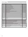
Contents
Safety precautions . . . . . . . . . . . . . . . . . . . . . . . . . . . . . . . . . . . . . . . . . . . . . . . . . . . . . . . . . . . . . . . . . . . . . . . . . . . . . . . . . . . . . . . . . . . . . . . . 2
Product specifications . . . . . . . . . . . . . . . . . . . . . . . . . . . . . . . . . . . . . . . . . . . . . . . . . . . . . . . . . . . . . . . . . . . . . . . . . . . . . . . . . . . . . . . . . . . . 4
Outdoor unit specification . . . . . . . . . . . . . . . . . . . . . . . . . . . . . . . . . . . . . . . . . . . . . . . . . . . . . . . . . . . . . . . . . . . . . . . . . . . . . . . . . . . . . . . 4
Main components . . . . . . . . . . . . . . . . . . . . . . . . . . . . . . . . . . . . . . . . . . . . . . . . . . . . . . . . . . . . . . . . . . . . . . . . . . . . . . . . . . . . . . . . . . . . . . . . 5
Installing the unit . . . . . . . . . . . . . . . . . . . . . . . . . . . . . . . . . . . . . . . . . . . . . . . . . . . . . . . . . . . . . . . . . . . . . . . . . . . . . . . . . . . . . . . . . . . . . . . . . 5
Electrical connections . . . . . . . . . . . . . . . . . . . . . . . . . . . . . . . . . . . . . . . . . . . . . . . . . . . . . . . . . . . . . . . . . . . . . . . . . . . . . . . . . . . . . . . . . . . 12
Connecting the cable . . . . . . . . . . . . . . . . . . . . . . . . . . . . . . . . . . . . . . . . . . . . . . . . . . . . . . . . . . . . . . . . . . . . . . . . . . . . . . . . . . . . . . . . . . . . 12
Refrigerant piping work . . . . . . . . . . . . . . . . . . . . . . . . . . . . . . . . . . . . . . . . . . . . . . . . . . . . . . . . . . . . . . . . . . . . . . . . . . . . . . . . . . . . . . . . . 16
Checking correct grounding . . . . . . . . . . . . . . . . . . . . . . . . . . . . . . . . . . . . . . . . . . . . . . . . . . . . . . . . . . . . . . . . . . . . . . . . . . . . . . . . . . . . . 27
Setting the option switch and function of the keys . . . . . . . . . . . . . . . . . . . . . . . . . . . . . . . . . . . . . . . . . . . . . . . . . . . . . . . . . . . . . . 28
Pump down procedure . . . . . . . . . . . . . . . . . . . . . . . . . . . . . . . . . . . . . . . . . . . . . . . . . . . . . . . . . . . . . . . . . . . . . . . . . . . . . . . . . . . . . . . . . . 30
Completing the installation . . . . . . . . . . . . . . . . . . . . . . . . . . . . . . . . . . . . . . . . . . . . . . . . . . . . . . . . . . . . . . . . . . . . . . . . . . . . . . . . . . . . . . 33
Final checks and trial operation . . . . . . . . . . . . . . . . . . . . . . . . . . . . . . . . . . . . . . . . . . . . . . . . . . . . . . . . . . . . . . . . . . . . . . . . . . . . . . . . . . 34
Trouble shooting . . . . . . . . . . . . . . . . . . . . . . . . . . . . . . . . . . . . . . . . . . . . . . . . . . . . . . . . . . . . . . . . . . . . . . . . . . . . . . . . . . . . . . . . . . . . . . . . 35
Error codes . . . . . . . . . . . . . . . . . . . . . . . . . . . . . . . . . . . . . . . . . . . . . . . . . . . . . . . . . . . . . . . . . . . . . . . . . . . . . . . . . . . . . . . . . . . . . . . . . . . . . . 35
Safety precautions
Carefully follow the precautions listed as below because they are essential to guarantee the safety of SAMSUNG
product.
WARNING
• Always disconnect a power supply of Air-Water Heat Pump before servicing it or
accessing components inside the unit.
• Verify that installation and testing operations shall be performed by qualified
personnel.
• To prevent serious damage on the system and injuries to users, precautions and
other notices shall be observed.
Warning
ffCarefully read the content of this manual before installing the air to water heat pump and store the manual in a safe place in
order to be able to use it as reference after installation.
ffFor maximum safety, installers should always carefully read the following warnings.
ffStore the operation and installation manual in a safe location and remember to hand it over to the new owner if the air
conditioner is sold or transferred.
ffStore the user and installation manual in a safe location and remember to hand it over to the new owner if the air to water heat
pump is sold or transferred.
ffThis manual explains how to install Air-Water Heat Pump. The use of other types of units with different control systems may
damage the units and invalidate the warranty. The manufacturer shall not be responsible for damages arising from the use of
non compliant units.
ffThis product has been determined to be in compliance with the Low Voltage Directive (2006/95/EC), and the Electromagnetic
Compatibility Directive (2004/108/EEC) of the European Union.
ffThe manufacturer shall not be responsible for damage originating from unauthorized changes or the improper connection
of electric and hydraulic lines. Failure to comply with these instructions or to comply with the requirements set forth in the
“Operating limits” table, included in the manual, shall immediately invalidate the warranty.
ffFailure to comply with these instructions or to comply with the requirement on the Operating Range (Heat: -20~35°C/Cool:
10~46°C) set forth in the Product Specification (p.5) shall immediately invalidate the warranty.
ffDo not use the units if you see some damages on the units and recognize something bad such as loud noisy, smell of burning.
ffIn order to prevent electric shocks, fires or injuries, always stop the unit, disable the protection switch and contact SAMSUNG’s
technical support if the unit produces smoke, if the power cable is hot or damaged or if the unit is very noisy.
ffAlways remember to inspect the unit, electric connections, refrigerant tubes and protections regularly. These operations shall
be performed by qualified personnel only.
ffThe unit contains moving parts and electrical parts, which should always be kept out of the reach of children.
2
3
ENGLISH
ffDo not attempt to repair, move, alter or reinstall the unit by unauthorized personnel, these operations may cause product
damage, electric shocks and fires.
ffDo not place containers with liquids or other objects on the unit.
ffAll the materials used for the manufacture and packaging of the air to water heat pump are recyclable.
ffThe packing material and exhaust batteries of the remote controller(optional) must be disposed of in accordance with local
regulations.
ffThe air to water heat pump containing a refrigerant must be disposed in authorized center or returned to retailer as special
wastes.
ffWear protective gloves to unpack, move, install, and service the unit to avoid your hands being injured by the edge of the parts.
ffDo not touch the internal parts (water pipes, refrigerant pipes, heat exchangers, etc) while running the units. And if you need to
adjust and touch the units, have enough time for the unit can be cooled and be sure to wear protective gloves.
ffIn case of refrigerant leakage, try to avoid getting in contact with the refrigerant because this could result in severe wounds.
ffWhen you install the Air to water heat pump in a small room, you must consider a proper ventilation to prevent a leakage level
within the maximum permissible limit.
-- In that case, you may die from suffocation by some possibility.
ffMake sure to safely dispose of packing materials. Packing materials, such as nails and other metal or wooden pallets may cause
children get injured.
ffInspect the product shipped and check if damaged during transport. If the product has some damages, DO NOT INSTALL and
immediately discuss about the damages with the carrier or retailer (if the installer or the authorized technician has collected
the material from the retailer.)
ffOur units shall be installed in compliance with the spaces described in the installation manual, to ensure accessibility from both
sides and allow repairs or maintenance operations to be carried out. If the units installed without complying with procedures
described in manual, additional expenses can be asked because special harnesses, ladders, scaffolding or any other elevation
system for repair service will NOT be considered part of the warranty and will be charged to the end customer.
ffAlways make sure that the power supply is compliant with local safety standards.
ffVerify that the voltage and frequency of the power supply comply with the specifications and input power is sufficient to
ensure the operation of any other domestic appliance connected to the same electric lines. Always verify that the cut-off and
protection switches are suitably selected.
ffAlways verify that electric connections (cable entry, section of leads, protections…) are compliant with the electric
specifications and with the instructions provided in the wiring scheme. Always verify that all connections comply with the
standards applicable to the installation of air to water heat pumps. Devices disconnected from the power supply should be
completely disconnected in the condition of overvoltage category.
ffDo not connect the earth wire to the gas pipe or water pipe, lighting rod, surge absorber, or telephone earth wire. If earthing is
not complete, it may cause an electric shock or fire.
ffBe sure to install both an earth leakage detector and circuit breaker with specified capacity in accordance with relevant local
and national regulations.
-- If it is not installed properly, it may cause electric shocks and fire.
ffMake sure that the condensed water runs well out of the unit at low ambient temperature. Drain pipe and cond heater can
frost/ice can not grow. If drain work is not effective for releasing condensed water, it can make the units get damaged by
massive ice and system can be stop , covered by ice.
ffInstall the power cable and communication cable of the indoor and outdoor unit at least 1m away from the electric appliance.
ffProtect the unit from rats or small animals. If an animal makes a contact with the electric parts, it can cause malfunctions,
smoke or fire. Please instruct the customer to keep the area around the unit clean.
Product specifications
Product line-up
Line-up
Remark
Chassis
Heat pump units
-
Model name
AEX060EDEHA
Accessories
ffKeep supplied accessories until the installation is finished.
ffHand the installation manual over to the customer after finishing installation.
ffThe quantities are indicated in parentheses.
Installation manual (1)
Drain plug (1)
Nipple-Connetor(1)
Outdoor unit specification
4
Type
Unit
AEX060EDEHA
Power source
-
1P, 220~240VAC 50Hz
Compressor
-
Rotary Inverter
Condenser
-
Ø7, L906
Fan & Motor
-
Propeller, Ø420,3-blade,BLDC Inverter
Refrigerant
kg
1.2
Noise
(Heat/Cool, Pressure)
dBA
53 / 54
Operating range
(Heat/Cool)
°C
-20~35 / 10~46
Leaving water
temperature
°C
Cooling : 5 ~ 25
Heating : 25 ~ 55
Weight (net/gross)
kg
47.5/52.5
Size (WxHxD, net)
mm
880X638X310
Rubber Leg(4)
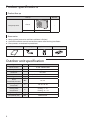
Main components
Dimensions(Overall)
Heat pump for R-410A.
12
23
364
610
ENGLISH
50
638
310
880
54.1
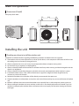
Installing the unit
Deciding on where to install the outdoor unit
Decide the installation location regarding the following condition and obtain the user’s approval.
ffThe outdoor unit must not be placed on its side or upside down, as the compressor lubrication oil will run into
the cooling circuit and seriously damage the unit.
ffChoose a location that is dry and sunny, but not exposed to direct sunlight or strong winds.
ffDo not block any passageways or thoroughfares.
ffChoose a location where the noise of the Air to Water Heat Pump when running and the discharged air do not
disturb any neighbours.
ffChoose a position that enables the pipes and cables to be easily connected to the other hydrauric system.
ffInstall the outdoor unit on a flat, stable surface that can support its weight and does not generate any
unnecessary noise and vibration.
ffPosition the outdoor unit so that the air flow directly stream towards the open area.
ffPlace the outdoor unit where there are no plants and animals because they may cause malfunction of outdoor
unit.
ffMaintain sufficient clearance around the outdoor unit, especially from a radio, computer, stereo system, etc.
ffWhen installing the outdoor unit near seashore, make sure it is not directly exposed to sea breeze. If you can
not find an adequate place without direct sea breeze, make sure to apply anti-corrosion coating on the heat
exchanger.
5
Installing the unit
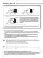
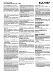
ffInstall the outdoor unit in a place (such as near buildings etc.) where it can be prevented from sea breeze
which can damage the outdoor unit.
Sea breeze
Outdoor
unit
Sea breeze
Sea
Outdoor
unit
Sea
ffIf you cannot avoid installing the outdoor unit by the seashore, construct a protection wall around to block
the sea breeze.
Protection wall
Sea breeze
Sea
Outdoor
unit
• Protection wall should be constructed with a solid material
such as concrete to block the sea breeze and the height and
the width of the wall should be 1.5 times larger than the
size of the outdoor unit. Also, secure over 700mm between
the protection wall and the outdoor unit for exhausted air
to ventilate.
ffInstall the outdoor unit in a place where water can drain smoothly.
* If you cannot find a place satisfying above conditions, please contact manufacturer. Make sure to clean the
sea water and the dust on the outdoor unit heat exchanger.
ffDo not install the Air to Water Heat Pump in following places.
• The place where there is mineral oil or arsenic acid. There is a chance that parts may get damaged due to
burned resin. The capacity of the heat exchanger may reduce or the Air to Water Heat pump may be out of
order.
• The place where corrosive gas such as sulfurous acid gas generates from the vent pipe or air outlet. The
copper pipe or connection pipe may corrode and refrigerant may leak.
• The place where there is a danger of existing combustible gas, carbon fiber or flammable dust. The place
where thinner or gasoline is handled.
CAUTION
CAUTION
• Do not install the outdoor unit in a snowy and cold area (low temperature and high humidity area where the temperature is below -7°C and humidity is higher than 85%) because according to operation
condition (defrost, etc.), ice may be formed in the drain route.
If the ice is accumulated, it may cause critical damage to the product.
ex) lakeside of cold area in winter time, seashore, alpine region and etc.
• This device must be installed according to the national electrical rules.
• With an outdoor unit having net weight upper than 60kg, we suggest do not install it suspended on wall,
but considering floor standing one.
ffIf the outdoor unit is installed at a height, ensure that its base is firmly fixed in position.
ffMake sure that the water dripping from the drain hose runs away correctly and safely.
ffWhen you install the outdoor unit at wayside, you should install it above 2m height or make sure that the heat
from the outdoor unit shouldn't be in direct contact with passersby. (The ground for application :The revision
of regulation for facility in building by the law of the Ministry of Construction and Transportation.
6
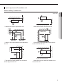
Space requirements for outdoor unit
When installing 1 outdoor unit
1,500 or more
300 or more
* When the air outlet is towards the wall
2,000 or more
600 or more
600 or more
* When 3 sides of the outdoor unit are blocked by
the wall
300 or more
* The upper part of the outdoor unit and the air
outlet is opposite the wall
* The upper part of the outdoor unit and the air
outlet is towards the wall
1,500 or more 300 or more
300 or more
1,500 or more
300 or more
* When the air outlet is opposite the wall
* When front and rear side of the outdoor unit is
towards the wall
7
ENGLISH
(Unit : mm)
Installing the unit
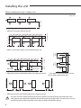
When installing more than 1 outdoor unit
1500 or more
(Unit : mm)
300 or more
* When the air outlet is towards the wall
300 or more
600 or more
600 or more
600 or more
600 or more
600 or more
* When front and rear side of the outdoor unit is towards the wall
1500 or more
600 or more
3000 or more
500 or
more
300 or more
500 or
more
300 or more
1500 or
more
300 or
more
* When 3 sides of the outdoor unit are blocked by the wall
3000 or more
* The upper part of the outdoor unit and
the air outlet is opposite the wall
300 or more
* When front and rear side of the outdoor unit is towards the wall
CAUTION
8
• The units must be installed according to distances declared, in order to permit accessibility from each
side, either to guarantee correct operation of maintenance or repairing products. The unit’s parts must be
reachable and removable completely under safety condition (for people or things).
Outdoor unit installation
(Unit : mm)
CAUTION
340
• When tightening the anchor bolt, tighten the rubber
washer to prevent the outdoor unit bolt connection
part from corroding.
• Make a drain outlet around the base for outdoor unit
drainage.
• If the outdoor unit is installed on the roof, you have to
check the ceiling strength and waterproof the unit.
364
Anchor bolt hole
310
NOTE
• The anchor bolt must be 20mm or higher from the
base surface.
660
880
Rubber leg
Outdoor unit support
Soft rubber designed to cut off
vibration from rack to wall. (not
supplied with product)
Outdoor
unit
Anchor bolt
20mm
Designed to cut off residual vibration
from outdoor unit to rack. (not supplied
with product)
Outdoor unit
support
Base surface
ffOutdoor unit installed on the wall by rack
-- Ensure the wall will be able to suspend the weight of rack and outdoor unit ;
-- Install the rack close to the column as much as possible ;
-- Install proper grommet in order to reduce noise and residual vibration transferred by outdoor unit towards
wall.
CAUTION
When installing air guide duct
• Check and make sure that screws do not damage the copper pipe.
• Secure air guide duct on guard fan.
9
ENGLISH
The outdoor unit must be installed on a rigid and stable base to avoid any increase in the noise level and vibration,
particularly if the outdoor unit is to be installed in a location exposed to strong winds or at a height, the unit must
be fixed to an appropriate support(wall or ground).
ffFix the outdoor unit with anchor bolts.
Installing the unit
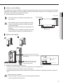
Drain work
ffIn case there is not enough space for drainage out of the unit, additional
drain works are required. Follow the description as below
-- Make space more than 50mm between the bottom of the outdoor unit
and the ground for installation of the drain hose.
-- Insert the drain plug into the hole on the bottom of the outdoor unit.
-- Connect the drain hose to the drain plug.
-- Make sure dusts or small branches should not go into the drain hose.
• If drain work is not enough, it can lead to system performance degration and system damages.
WARNING
Drain hole Ø20
Air discharge side
30 mm
Drain plug x 1ea
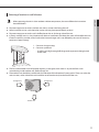
1. Prepare a water drainage channel around the foundation, to drain waste water from around the unit.
2. If the water drainage of the unit is not easy, please build up the unit on a
foundation of concrete blocks, etc. (the height of the foundation should be
maximum 150mm).
3. If you install the unit on a frame, please install a waterproof plate within
150mm of the underside of the unit in order to prevent the invasion of water
from the lower direction.
4. When installing the unit in a place frequently exposed to snow, pay special
attention to elevate the foundation as high as possible.
5. If you install the unit on a building frame, please install a waterproof plate
(field supply) (within 150mm of the underside of the unit) in order to avoid
the drain water dripping. (See figure)
10
≥50mm
While Air-Water Heat Pump is running in heating mode, Ice can begin accumulate on the surface of condenser. To
prevent Ice from growing, system go into De-frost mode and then Ice on the surface changes to water.
Dropped water from condenser shall be eliminated through running drain holes to prevent Ice growing at low
temperature.
Selecting a location in cold climates
• When operating the unit in a low outdoor ambient temperature, be sure to follow the instructions
described below.
ENGLISH
NOTE
ffTo prevent exposure to wind, install the unit with its suction side facing the wall.
ffNever install the unit at a site where the suction side may be exposed directly to wind.
ffTo prevent exposure to wind, install a baffle plate on the air discharge side of the unit.
ffIn heavy snowfall areas it is very important to select an installation site where the snow will not affect the unit.
If lateral snowfall is possible, make sure that the heat exchanger coil is not affected by the snow (If necessary
construct a lateral canopy)
1. Construct a large canopy.
2. Construct a pedestal.
-- Install the unit high enough off the ground to prevent it being buried
under snow.
ffThe fan inside outdoor unit will operate regularly, as designed, with switch 2 to prevent from snow
accumulating inside outdoor unit. (Refer to page 29)
ffThe outdoor unit should be installed with consideration of the direction of strong winds. These can make the
unit turn over, so the side of the unit should be set to face the wind, not the front of the unit.
Strong wind
Strong wind
blown air
11
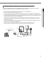
Electrical connections
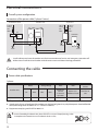
Overall system configuration
Connection of the power cable (1 phase 2 wires)
Distribution board
Outdoor unit
Hydro unit
1 phase
2 wires
220240V~
1 phase
2 wires
220240V~
ELCB
Or
MCCB+
ELB
1 phase
2 wires
220240V~
DHW tank
Earth
Earth
Earth
Communication cable
CAUTION
• Install cabinet panel near the outdoor unit for the convenience of service and emergency operation off.
• Make sure to install the circuit breaker with the over-current and electric leakage protection.
Connecting the cable
Power cable specifications
1 phase
Rated
Voltage Range
MFA
Fuse cut-off
current
Hz
Volts
Min
Max
Maximum
Current
in normal
operation
MCA1.25 +
Additional Load
Total fuse in
unit
50
220-240
198
264
20 A
25 A
30 A
Outdoor unit
AEX060EDEHA
MCA
ffThe power cable is not supplied with air conditioner.
ffSupply cords of parts of appliances for outdoor use shall not be lighter than polychloroprene sheathed flexible
cord (Code designation IEC:60245 IEC 57 / CENELEC:H05RN-F)
ffEquipment complying with EN/IEC 61000-3-12.
• In case of extending the electric wire, please DO NOT use a round-shaped pressing socket.
- Incomplete wire connections can cause electric shock or a fire.
12
Connecting the cable
Between indoor unit and outdoor unit connection cable specifications(common in use)
Power supply
Max/Min(V)
Indoor power cable
1Φ, 220-240V, 50Hz
±10%
0.75~1.5mm², 3wires
Communation cable
ENGLISH
Power supply
0.75~1.5mm², 2wires
ffFor Indoor Power Cable, use the grade H07RN-F or H05RN-F materials.
When installing the indoor unit in a computer room or net work room, use
the double shielded (Tape aluminum / polyester braid + copper ) cable of
FROHH2R type.
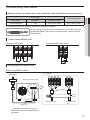
1-phase terminal block spec
AC power : M4 screw
Communication : M4 screw
N
L
11.4
10.1
10.1
11.4
Wiring diagram of power cable
When using ELB for 1 phase
ff1 phase
Power Supply
MCCB
Electrical component box
L
N
ELB
MCCB
Cable tie
Cable
clamp
Main power cable
Hydro unit
Communication
cable
* The appearance of the unit may be
different from the picture depending on
the model.
13
Connecting the cable
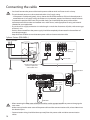
CAUTION
• You should connect the power cable into the power cable terminal and fasten it with a clamp.
• The unbalanced power must be maintained within 2% of supply rating.
-- If the power is unbalanced greatly, it may shorten the life of the condenser. If the unbalanced power is
exceeded over 4% of supply rating, the indoor unit is protected, stopped and the error mode indicates.
• To protect the product from water and possible shock, you should keep the power cable and the
connection cord of the indoor and outdoor units within ducts. (with appropriate IP rating and material
selection for your application)
• Ensure that main supply connection is made through a switch that disconnects all poles, with contact gap
of a least 3 mm.
• Devices disconnected from the power supply should be completely disconnected in the condition of
overvoltage category.
• Keep distances of 50mm or more between power cable and communication cable.
1 phase 2 wires (220-240V~)
1 phase 220-240V~
Circuit
breaker
Earth cable
(U-Trap)
Power cable
Communication cable
between Hydro unit
and outdoor units
Earth
Communication
cable
F1
N
L
N
L
N
L
F2
1 phase 1 phase
220-240V~ 220-240V~
Hydro unit
DHW Tank
CAUTION
14
• When removing the outer cover of the power cable, use the appropriate tools to prevent damaging the
inner cover.
• Make sure to place the outer cover of the power cable and the communication cable, at least 20mm into
the electrical parts.
• Communication wiring should be done separately from the power cable and other communication
cables.
Connecting the power terminal
Tightening Torque (kgf.cm)
M4
12.0~14.7
M5
24.4~29.8
Installing the earth wire
ffEarthing must be done by your installation specialist for your safety.
ffUse the earth wire by referring to the specification of the electric cable for the outdoor unit.
Earthing the power cable
ffThe standard of earthing may vary according to the rated voltage and installation place of the Air to Water Heat
Pump.
ffEarth the power cable according to the following.
Installation place
Power condition
High humidity
Electrical potential of lower than 150V
Electrical potential of higher than 150V
Average humidity
Low humidity
Perform the earthing work
3. Note 1)
Perform the earthing work 2 if
possible for your safety. Note 2)
Must perform the earthing work 3. Note 1)
(In case of installing circuit breaker)
* Note 1) Earthing work 3
-- Earthing must be done by your installation specialist.
-- Check if the earthing resistance is lower than 100Ω. When installing a circuit breaker that can cut the electric
circuit in case of a short circuit, the allowable earthing resistance can be 30~500Ω.
* Note 2) Earthing at dry place
-- The earthing resistance should be lower than 100Ω. (Even in worst case it should be lower than 250Ω.)
ffWhen using the terminal for earthing only
Earth
terminal
ffWhen using earthing of the switchboard
Distribution
Board
15
ENGLISH
ffConnect the cables to the terminal board using the compressed ring terminal.
ffConnect the rated cables only.
ffConnect using a wrench which is able to apply the rated torque to the screws.
ffIf the terminal is loose, fire may occur caused by arc. If the terminal is connected too firmly, the terminal may be
damaged.
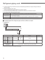
Refrigerant piping work
ffInstall the refrigerant pipe within the maximum allowable length, difference in height and length of after the
first branch pipe.
ffThe pressure of the R-410A is high.
Use only rated refrigerant pipe and follow the installation method.
ffUse clean refrigerant pipe Where there is no harmful ion, oxide, dust, iron content or moisture.
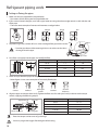
ffUse adequate tools and accessories for R-410A.
Manifold gauge
• Use manifold gauge only for R-410A to prevent the inflow of foreign substances.
Vacuum pump
• Use vacuum pump with check valve to prevent pump oil from flowing backward while the
vacuum pump is stopped.
• Use the vacuum pump that the vacuum induction is available up to 5Torr. (-100.7kPa)
Flare nut
• Use only flare nut supplied with the product.
Allowable length of the refrigerant pipe and the installation examples
ffAEX060EDEHA,
Outdoor unit
Item
Maximum
allowable
length of
pipe
Outdoor unit
~ Hydro unit
Maximum
allowable
height
Outdoor unit
~ Hydro unit
Additional refrigerant
calculation
Example
Total length
Less than
30m
Less than 20m
H1
R=Basic charge + additional charge by the piping length
Contact the manufacturer if the length should exceed.
16
a ≤ 30m
Remarks
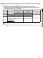
Selecting the refrigerant pipe
Liquid side
(mm)
Gas side (mm)
Outer
diameter (mm)
Minimum
thickness
(mm)
AEX060EDEHA
ø6.35
ø15.88
ø 6.35
0.7
ø 9.52
0.7
ø12.70
0.8
ø15.88
1.0
ø15.88
0.8
ø19.05
0.9
ø22.23
0.9
ffInstall refrigerant pipe depending on the outdoor unit
capacity.
ffMake sure to use C1220T-1/2H (Semi-hard) pipe for
more than Ø19.05mm. In case of using C1220T-O (Soft)
pipe for Ø19.05mm, pipe may be broken, which can
result in an injury.
Temper grade
ENGLISH
Outdoor unit capacity (kW)
C1220T-0
C1220T-1/2H OR
C1220T-H
* Temper grade and minimum thickness of the
refrigerant pipe
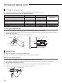
Keeping refrigerant pipe clean and dry
ffTo prevent foreign materials or water from entering the pipe, pipes shall be sealed by caps.
Installing the Nipple
ffBefore connecting the refrigerant pipe, the Nipple must be connected to liquid side pipe of Hydro unit.
Assemble
Disassemble
Liquid Gas
pipe pipe
Liquid Gas
pipe pipe
WATER WATER
OUTLET INLET
WATER WATER
OUTLET INLET
17
Refrigerant piping work
Cutting or flaring the pipes
1. Make sure that you prepared the required tools.
-- Pipe cutter, reamer, flaring tool and pipe holder, etc.
2. If you want to shorten the pipe, cut it with a pipe cutter ensuring that the cut edge remains at 90° with the side
of the pipe.
-- There are some examples of correct and incorrect cut edges below.
Oblique
90°
Rough
Burr
Burr
3. To prevent a gas leak, remove all burrs at the cut edge of the pipe with a reamer. Pipe
CAUTION
• Face the pipe down while removing the burrs to make sure that burrs
do not get in to the pipe.
Pipe cutter
4. Put a flare nut slightly into the pipe and modify the flare.
Pipe
Outer diameter [D(mm)]
Depth [A (mm)]
ø 6.35
1.3
9.0
ø 9.52
1.8
13.0
ø 12.70
2.0
16.2
ø 15.88
2.2
19.3
ø19.05
2.2
22.5
Flare
Flaring Size [B (mm)]
5. Check that you flared the pipe correctly.
-- Below figures shows some examples of incorrectly flared pipes.
Correct
Inclined
Damaged
surface
Cracked
Uneven
thickness
6. Align the pipes to connect them easily. Tighten the flare nuts first with your hands, and then with a torque
wrench, applying the following torque:
Apply frozen oil
Indoor outlet pipe
NOTE
Flare nut
Connecting pipe
Outer diameter (mm)
Torque (N•m)
ø 6.35
12~17
ø 9.52
30~35
ø 12.70
40~45
ø 15.88
50~60
ø19.05
60~70
• Excessive torque can be cause of gas leakage.
• You must purge with oxygen free nitrogen while brazing.
CAUTION
18
Selecting the insulator of the refrigerant pipe
Thickness of insulator
Pipe type
Pipe diameter (mm)
Normal
(Under 30°C, 85%)
High humidity
(Over 30°C, 85%)
ø6.35~ø19.05
9
9
ø12.70~ø19.05
13
13
ø6.35
13
19
19
25
Remarks
EPDM, NBR
Liquid
ø9.52
Gas
ø12.70
ø15.88
The material shall has
heat resistant over
120°C
ø19.05
CAUTION
• Install the insulation not to be get wider and use the adhesives on the connection part of it to prevent
moisture entering.
• Wind the refrigerant pipe with insulation tape if it is exposed to outside sunlight.
• Install the refrigerant pipe respecting that the insulation does not get thinner on the bent part or hanger
of pipe.
19
ENGLISH
ffAccording to pipes size, insulate pipes on gas and liquid side by selecting appropriate insulations.
ffStandard condition is under a temperature of 30°C and a humidity of 85%. If the units are installed in extreme
weather conditions, select the insulator by table below.
Refrigerant piping work
Insulating the refrigerant pipe
ffYou must check if there is a gas leak before completing all the installation process.
ffUse EPDM insulation which meets the following condition.
Item
Density
Dimension change route by heat
Water absorption rate
Thermal conductivity
Moisture transpiration factor
Moisture transpiration grade
Formaldehyde dispersion
Oxygen rate
Unit
g/cm²
%
g/cm²
kcal/m·h·˚C
ng/(m²·s·Pa)
{g/(m²·24h)}
mg/L
%
Standard
0.048~0.096
-5 or less
0.005 or less
0.032 or less
15 or less
15 or less
25 or less
Remarks
KSM 3014-01
KSL 9016-95
KSM 3808-03
KSA 1013-01
KSF 3200-02
ISO 4589-2-96
Insulating the refrigerant pipe
ffBe sure to insulate the refrigerant pipe, joints and connections with class 'o' material.
ffIf you insulate the pipes, the condensed water does not fall from the pipes and the capacity of the Air to Water
Heat Pump is improved.
ffCheck if there are any insulation cracks on the bent pipe.
Insulation
Clamp
Insulation
Overlapped
Indoor unit
Indoor unit
Gas side pipe
Liquid side pipe
Install the insulation
to be overlapped
Brazing the Pipe
ffMake sure that there is no moisture inside the pipe.
ffMake sure that there are no foreign materials and impurities in the pipe.
Replacement of Nitrogen gas
1. Use oxygen free nitrogen gas when brazing the pipes as shown in the picture.
2. If you do not use Nitrogen gas when brazing the pipes, oxidation may form in the pipe. It can cause the
damage of the compressor and valves.
3. Adjust the flow rate of the replacement with a pressure regulator to maintain 0.05m3/h or more.
4. Perform brazing of the service valve after protecting the valve.
Brazing part
1/4" copper pipe
Nitrogen gas
Pressure regulator Valve stem
Taping
20
Performing the refrigerant gas leak test
ENGLISH
ffUse a manifold gauge for R-410A to prevent the inflow of foreign substances and resist against the internal
pressure.
ffPressure test with dry oxygen free nitrogen only.
Apply pressure to the liquid side pipe and gas
side pipe with Nitrogen gas of 4.1 MPa (41.8
kgf/cm²)
If you apply pressure more than 4.1MPa, the pipes may be
damaged. Apply pressure using pressure regulator.
Keep it for minimum 24 hours to check if the
pressure drops.
After applying Nitrogen gas, check the change of pressure
using pressure regulator.
If the pressure drops, check if there is gas leak.
If the pressure is changed, apply soapy water to check the
leak. Check the pressure of the Nitrogen gas again.
Maintain 1.0MPa of the pressure before
performing vacuum drying and check further
gas leak.
After checking first gas leak, maintain 1.0MPa to check further
gas leak.
Manifold gauge
Low pressure side
Service port
High pressure side
Pressure adjustment
valve (mandatory)
Nitrogen
gas
* Make sure to use a recommended bubble test solution for Gas Leak Test. Soap water could cause cracking of the
flare nuts or lead to corrosion of flared joints.
CAUTION
• You may get injured when the joint on the high pressure side detaches and the gas comes in contact with
your body. Make sure to tighten the joint to prevent such accidents.
21
Refrigerant piping work
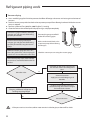
Vacuum drying
ffUse a manifold gauge for R-410A to prevent the inflow of foreign substances and resist against the internal
pressure.
ffUse the vacuum pump with the check valve to prevent pump oil from flowing backward while the vacuum
pump is stopped.
ffVacuum system to 5Torr. (666.6Pa, 0.0067 kgf/cm², 5 mmHg)
ffClose the service valve of the liquid side pipe and gas side pipe completely.
Connect the gauge manifold to the liquid
side pipe, gas side pipe and oil balancing
pipe(only for module).
Connect the gauge manifold
to the oil balancing pipe.
Perform vacuum drying of the liquid
side pipe, gas side pipe and oil balancing
pipe(only for module) using the vacuum
pump.
Make sure that install check valve
to prevent pump oil from flowing
into the pipe.
While the vacuum gauge pressure is less
than 5Torr, perform the vacuum drying for
more than 1 hour and then close the valve.
Check the vacuum pressure using the vacuum gauge.
Vacuum
pump
After vacuum pump stops, check whether
the pressure is maintained within 5Torr for
an hour.
More than 5Torr
Yes
Check the gas leak again.- The pressure
rises because water is remaining in the
pipe.
Vacuum destruction
- Apply pressure with Nitrogen gas of
0.05MPa.
No
Charging additional refrigerant according to piping length
No
Perform vacuum drying again up to
666.6Pa(5mmHg) (for 2 hours or longer)
and evaluate the vacuum.
Pressure Increase
• If the pressure rises in an hour, either water remains inside the pipe, or there will be a leak.
CAUTION
22
Yes
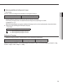
Selecting additional refrigerant charge
Outdoor unit (Series)
Factory charge(kg)
AEX060EDEHA
1.2
ENGLISH
* Basic charge
The basic amount of refrigerant for outdoor unit charged in factory is:
* Charge additional refrigerant according to the total length of the pipe.
Each factory charging values are determined according to basic pipe length as below.
AEX060EDEHA ≤ 5m
When extra pipe length are required, additional charging works must be implemented as describes below.
ffDepends on the total length of the liquid side pipe.
-- Air to Water
Additional Charge(g) = {(L1-5)x20}+{(L2-5)x50}
NOTE
• L1: Total length of liquid pipe Ø 6.35(m)
L2: Total length of liquid pipe Ø 9.52(m)
Refrigerant Charging
* Additional charging amount is determined based on liquid pipe specifications.
Outdoor unit of liquid
ø6.35
ø9.52
Additional charging (g)
20g/m
50g/m
Additional charging amount = (sum of total length (m) of ø9.52) × 50g + (sum of total length (m) of ø6.35) × 20g
Ex) 20m × 50g/m + 20m × 20g/m = 1,400g
23
Refrigerant piping work
Charging refrigerant
ffThe R-410A refrigerant is blended refrigerant. Add only liquid refrigerant.
ffMeasure the quantity of the refrigerant according to the length of the liquid side pipe. Add quantity of the
refrigerant using a scale.
Important information regulation regarding the refrigerant used
This product contains fluorinated greenhouse gases covered by the Kyoto Protocol. Do not vent gases into the
atmosphere.
• Inform user if system contains 3kg or more of fluorinated greenhouse gases. In this case, it has to be
checked for leakage at least once every 12 months, according to regulation N°842/2006. This activity has
CAUTION
to be covered by qualified personnel only.
• In case situation above (3kg or more of R-410A), installer (or recognized person which has responsibility
for final check) has to provide a maintenance book, with all the information recorded according to
REGULATION (EC) N° 842/2006 OF THE EUROPEAN PARLIAMENT AND OF THE COUNCIL of 17 May 2006 on
certain fluorinated greenhouse gases.
Please fill in with indelible ink,
ff① The factory refrigerant charge of the product.
ff② The additional refrigerant amount charged in the field.
ff①+② The total refrigerant charge.
The refrigerant charge label supplied with the product.
NOTE
a Factory refrigerant charge of the product: See unit name plate.
b Additional refrigerant amount charged in the field. (Refer
to the above information for the quantity of refrigerant
replenishment.)
c Total refrigerant charge.
d Refrigerant cylinder and manifold for charging.
Refrigerant type
GWP value
R-410A
1975
* GWP=Global Warming Potential
Contains fluorinated greenhouse gases
covered by the Kyoto Protocol.
Indoor unit
②
d
a
①=(
②= (
b
) kg
) kg
①
Outdoor unit
①+②= ( ) kg
c
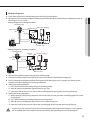
ffBefore charging, check whether the refrigerant cylinder has a siphon attached or not and position the cylinder
accordingly.
Charging using a cylinder with a
siphon attached
Charge the liquid refrigerant
with the cylinder in upright
position.
24
Charging using a cylinder
without a siphon attached
Charge the liquid refrigerant
with the cylinder in up-sidedown position.
Adding refrigerant
Manifold gauge
Low pressure
side
Outdoor unit
High pressure
side
Liquid side
Gas side
Suction charging
Service valve
Scale
* Adding refrigerants in heating conditions
Manifold gauge
Low
pressure
side
Scale
High pressure
side
Gas side
Outdoor
unit
Suction charging
Liquid side
Service valve
ffConnect the manifold gauge and purge the manifold gauge.
ffOpen the manifold gauge valve of the liquid side service valve and add the liquid refrigerant.
ffIf you cannot fully recharge the additional refrigerant while the outdoor unit is stopped, use the key on the
outdoor unit PCB to recharge the remaining refrigerant.
ffAdding the cooling refrigerant
1) Press the function key for adding refrigerant in cooling mode.
2) After 20 minutes of operation, open the valve on gas side.
3) Open the valve for low pressure side on the manifold gauge to recharge the remaining refrigerant.
ffAdding the heating refrigerant
1) When recharging the heating refrigerant, connect the low pressure pipe from manifold gage to the suction
charging port.
2) Press the function key for adding refrigerant in heating mode.
3) After 20 minutes of operation, open the valve on suction charge port.
4) Open the valve for low pressure side on the manifold gage to recharge the remaining refrigerant.
CAUTION
• Open the gas side and liquid side service valve completely after charging the refrigerant. (If you operate
the Air to Water Heat Pump with the service valve closed, the important parts may be damaged.)
25
ENGLISH
ffThe R-410A refrigerant is blended refrigerant. Add only liquid refrigerant.
ffMeasure the quantity of the refrigerant depending on the length of the liquid side pipe. Add fixed quantity of
the refrigerant using a scale.
* Adding refrigerants in cooling conditions
Refrigerant piping work
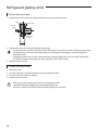
To close the valve stem
1. Open the cap and turn the valve stem clockwise by using a hexagonal wrench.
Cap
Valve stem
Service
port
Sealing
edge
2. Tighten the valve stem until it reached the sealing edge.
• Do not apply excessive force to the valve stem and always use special instruments. Otherwise, the contact
surface between valve stem and sealing edge can be damaged and refrigerant can leak through this
NOTE
damaged surface.
• If refrigerant would leak, turn the valve stem back by half and tighten the valve stem again, then check
the leakage. If there is no leakage any more, tighten the valve stem entirely.
3. Tighten the cap securely.
To open the valve stem
1.
2.
3.
4.
Remove the cap.
Turn the valve stem counterclockwise by using a hexagonal wrench.
Turn the valve stem until it is stopped.
Tighten the cap securely.
CAUTION
26
• When you use the service port, always use a charging hose, too.
• Check the leakage of refrigerant gas after tightening the cap.
• Must use a spanner and wrench when you open/tighten the valve stem.
Checking correct grounding
If the power distribution circuit does not have a grounding or the grounding does not comply with specifications,
an grounding electrode must be installed. The corresponding accessories are not supplied with the air conditioner.
1. Select an grounding electrode that complies with the specifications given in the illustration.
50cm
Steel core
Terminal M4
PVC-insulated green/ To grounding
screw
yellow wire
ENGLISH
Carbon
plastic
30cm
2. Connect the flexible hose to the flexible hose port.
ffIn damp hard soil rather than loose sandy or gravel soil that has a higher grounding resistance.
ffAway from underground structures or facilities, such as gas pipes, water pipes, telephone lines and
underground cables.
ffAt least two metres away from a lightening conductor grounding electrode and its cable.
NOTE
• The grounding wire for the telephone line cannot be used to ground the air conditioner.
3. Finish wrapping insulating tape around the rest of the pipes leading to the outdoor unit.
4. Install a green/yellow coloured grounding wire :
ffIf the grounding wire is too short, connect an extension lead, in a mechanical way and wrapping it with
insulating tape (do not bury the connection).
ffSecure the grounding wire in position with staples.
NOTE
• If the grounding electrode is installed in an area of heavy traffic, its wire must be connected securely.
5. Carefully check the installation, by measuring the grounding resistance with a ground resistance tester. If
the resistance is above required level, drive the electrode deeper into the ground or increase the number of
grounding electrodes.
6. Connect the grounding wire to the electrical component box inside of the outdoor unit.
27
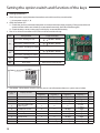
Setting the option switch and function of the keys
Testing operations
1. Check the power supply between the outdoor unit and the auxiliary circuit breaker.
• 1 phase power supply : L, N
2. Check the Indoor unit
1) Check that you have connected the power and communication cables correctly. (If the power cable and
communication cables one mixed up or connected incorrectly, the PCB will be damaged.)
2) Check the temp. sensor, water pump, and display are connected correctly.
3. Press K1 or K2 on the outdoor unit PCB to run the test mode and stop.
KEY
K1
KEY operation
7-segment display
Press once : Heating test run
" " " " "BLANK" "BLANK"
Press twice : Defrost test run
" " " " "BLANK" "BLANK"
Press 3times : Finishing test mode
-
Press once : Cooling test run
K2
" " " " "BLANK" "BLANK"
Press twice : Finishing test mode
K3
Reset
K4
View mode
-
Refer to View mode display
ON
1 2 3 4
5 6
7 8
4. View Mode : When the K4 switch is pressed, you can see information about our system state as below.
Number of
press
Display contents
0
Communication State
1
Order frequency
2
Units
Segment 2
Segment 3
Segment 4
10s digit of Tx
1s digit of Tx
10s digit of Rx
1s digit of Rx
1
100s digit
10s digit
1s digit
Hz
2
100s digit
10s digit
Hz
4
Current frequency
Type of Outdoor unit
(Mono/Split)
Outdoor air sensor
5
3
0
0
4
+/-
10s digit
1s digit
0 : split
1 : mono
1s digit
Discharge sensor
5
100s digit
10s digit
1s digit
°C
6
PHE (Eva) sensor
6
+/-
10s digit
1s digit
°C
7
Cond sensor
7
+/-
10s digit
1s digit
°C
8
Current
8
10s digit
1s digit
First decimal
A
9
Fan RPM
9
1000s digit
100s digit
10s digit
rpm
3
28
Display
Segment 1
°C
Number of
press
10
12
13
Display
Segment 1
Target discharge
temperature
EEV
Not used exchanger
capacity
Segment 2
Segment 4
Units
A
100s digit
10s digit
1s digit
°C
B
100s digit
10s digit
1s digit
step
C
Protection control
Segment 3
0
0
0
kW
D
0 : air
conditioning
1 : heating
Protection
control
0 : no
protection
control
1 : freezing
2 : non-stop
defrosting
3 : over-load
4 : discharge
E
100s digit
10s digit
1s digit
°C
F
set
Frequency
state
0 : Normal
1 : Hold
2 : Down
3 : Up_limit
4 : Down_limit
-
100s digit
10s digit
1s digit
long-1
Temperature of
Heatsink at PBA
The Quantity of
connected Indoor Unit
Main Micom version
Year(Hex)
Month(Hex)
Day(two digit)
Day(One digit)
-
long-1and 1
Inverter Micom version
Year(Hex)
Month(Hex)
Day(two digit)
Day(One digit)
-
long-1and 2
EEPROM version
Year(Hex)
Month(Hex)
Day(two digit)
Day(One digit)
-
14
15
5. DIP Switching setting
KEY
ON (default)
OFF
Switch 1
Auto Address
(Outdoor unit recognize the
address of indoor unit by random
access.)
Manual Address
(Outdoor unit recognize the address of
indoor unit by rotary switch of indoor unit.)
Switch 2
Anti-stack snow mode OFF
Anti-stack snow mode ON
Remark
Switch 1 must
be'ON'
Switch 3
x
Not defined
Switch 4
x
Not defined
29
ENGLISH
11
Display contents
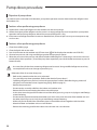
Pump down procedure
Objective of pump down
For product repairs and indoor unit relocation, pump down operation must be done recover the refrigerant into
the outdoor unit.
Cautions when performing pump down
ffProduct limits amount of refrigerant in the outdoor unit due to slim design.
ffCollect the majority of the refrigerant in the system in an empty refrigerant vessel and perform a pump down
operation with remaining refrigerant. Maximum amount of refrigerant is 5Kg.
ffIf the amount of refrigerant exceeds maximum allowable limit, increased pressure may cause compressor trip
or a burn out.
Cautions when performing pump down
1.
2.
3.
4.
5.
Close the manifold gauge.
Close the liquid side service valve.
Press the K2 button on the outdoor unit PCB one time. ( will be displayed on outdoor unit PCB LED.)
Observe low pressure side using manifold gauge when the compressor moves.
When the pressure on low pressure side decrease below 0 MPa(0 kgf/cm²) close the gas side service valve and
end the pump down operation. (To end the pump down operation, press the K2 button once more or press K3
button to reset.)
CAUTION
NOTE
30
• Use a transfer cylinder when recovering refrigerant to be reused. Using modified refrigerant vessel may
cause explosion and cause damage or personal injury.
Relocation of the Air to water heat pump
• Refer to this procedure when the unit is relocated.
• Carry out the pump down procedure. (Refer to the details of ‘pump down’.)
• Collecting refrigerant may be hard, since multi type products exceeds allowable charging amount of
refrigerant in the outdoor unit to support long piping. (Refer to page 31.)
• Remove the power cord.
• Disconnect the assembly cable from the indoor and outdoor units.
• Remove the flare nut connecting the indoor unit and the pipe.
• At this time, cover the pipe of the indoor unit and the other pipe using a cap or vinyl plug to avoid foreign
material entering.
• Disconnect the pipe connected to the outdoor unit. At this time, cover the valve of the outdoor unit and
the other pipe using a cap or vinyl plug to avoid foreign material entering.
• Make sure you do not bend the connection pipes in the middle and store together with the cables.
• Move the indoor and outdoor units to a new location.
• Remove the mounting plate for the indoor unit and move it to a new location.
Collecting refrigerant in refrigerant vessel before pump down operation
1.
2.
3.
4.
5.
6.
7.
8.
Prepare an exclusive rechargeable refrigerant vessel, scale and a manifold gauge.
Check the amount of refrigerant in the entire system.
Connect a refrigerant vessel to an outdoor unit and operated about 50% of the indoor unit in cooling mode.
After 10 minutes of cooling operation, check the pressure on high pressure side with the manifold gauge. If the
pressure on the high pressure side is over 3.0 MPa (30.59 kgf/cm²) reduce the number of operating indoor unit
to decrease the pressure below 3.0 MPa (30.59 kgf/cm²).
When the pressure becomes lower than 3.0 MPa (30.59 kgf/cm²) open the manifold gauge valve ② which is
connected to a liquid side. Then, open the valve on the refrigerant vessel for the refrigerant to flow from the
liquid side pipe to a vessel.
Check the weight difference with the scale. When desired amount of the refrigerant is collected into the vessel,
close the valve and remove the manifold gauge.
Make sure that the amount of the refrigerant in the vessel is about 50% of the entire system.
Measure the amount of refrigerant correctly to not exceed amount of collected refrigerant.
Outdoor unit
Gas side
R-410A
Liquid side
Refrigerant
vessel valve
Valve ①
Valve ②
Scale
Manifold gauge
Service valve
31
ENGLISH
If the amount of refrigerant in the system exceeded the maximum allowable limit, reduce the amount of the
refrigerant by following the below instruction before pump down operation.
Pump down procedure
When refrigerant recovery is difficult due to the large amount of refrigerant
1. Prepare manifold gauge, scale and an empty refrigerant vessel.
2. As shown below, connect the middle hose of manifold gauge to the refrigerant vessel and then connect the
both ends of manifold gauge to the outdoor unit service valve individually. (Valve of refrigerant vessel and Low
pressure side valve must be closed and the high pressure side valve must be open.)
3. Start refrigerant recovery operation by pressing K2 button one time.
4. After operating for 10 minutes, open the valve of refrigerant vessel and fill it with refrigerant.
5. Close the valve of refrigerant vessel when sufficient refrigerant is filled.
6. Close the liquid service valve immediately. When the low pressure falls down lower than 0, close the gas service
valve.
7. Stop the operation by pressing reset button.
Manifold gauge
Low pressure side
High pressure side
Service port
An empty
refrigerant
vessel
32
scale
Completing the installation
ffCheck the following after completing the installation.
ENGLISH
Outdoor unit
• Check the external surface and the inside of the outdoor unit.
• Is there any possibility of short circuit?
• Is the place well-ventilated and ensures space for service?
• Is the outdoor unit fixed securely?
Installation
Indoor unit
Adding refrigerant
• Check the external surface and the inside of the indoor unit.
• Is the place well-ventilated and ensures space for service?
• Check if the center of the indoor unit is ensured and it is installed horizontally.
• Is total number of connecting indoor units in the allowable range?
• Are the length and the difference between the refrigerant pipes within the
allowable range?
• Is the Y-joint properly installed?
• Is the pipe properly insulated?
• Is the quantity of the additional refrigerant correctly weighed in?
Installing the drain pipe
• Check the drain pipe of the outdoor unit and the indoor unit.
• Have you completed the drain test?
• Is the drain pipe properly insulated?
Installing the wiring
• Have you performed the earthing work 3 to the outdoor unit?
• Is 2-core cable used?
• Is the length of the wire is in the limited range?
• Is the wiring route correct?
Setting ADDRESS
• Are the ADDRESSES of the indoor and outdoor unit properly set?
33
Final checks and trial operation
Turn on the outdoor unit 3 hours before the test operation to preheat the compressor. If the compressor is not
preheated, ‘CH’ will appear on the outdoor unit PCB.
Inspection before test operation
1. Check the power cable and communication cable of the indoor and outdoor unit.
2. Check the power supply between the outdoor unit and the cabinet panel.
-- Check the 220-240V~ with the voltage meter.
3. Once the outdoor unit is turned on, it performs the tracking to check the connected indoor unit and options.
Test operation
1. Run the unit by KEY MODE or controller.
-- 1st- Running a indoor units by KEY MODE.
2nd- Each indoor unit runs separately by controller.
-- Inspect the compressor sound during the initial operation. If roaring sound is heard, stop operation.
2. Check the indoor and outdoor units’ running status.
-- Check if back light of remocon to be lighten by pushing the buttons without any error codes
-- Indoor and outdoor unit’s abnormal running noise.
-- Check detail running status using S-NET program.
3. Finish test.
4. Explain to the customer how to use the Air to Water Heat Pump following the user’s manual.
Filling out the installation check card and storing it inside of the outdoor unit
ffThe installation check card is enclosed in the installation manual.
ffInstallation engineer should fill out the installation card honestly.
-- Basic contents such as installation date, name of engineer, contact number, service company, etc.
-- Additional contents such as model name of outdoor unit, remarks, refrigerant calculation due to additional
pipe, etc.
-- Contents related indoor unit such as the place where indoor unit is installed, model name of indoor unit, etc.
ffStore the installation check card inside of the outdoor unit and make sure not to lose it.
34
Trouble shooting
WARNING
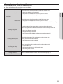
Error codes
If the unit has some problems and does not work normally, error code is shown on the OUTDOOR UNIT main PBA
or LCD of the wired remote controller.
Display
Explanation
Error Source
HYDRO UNIT,
OUTDOOR UNT
101
Hydro-Unit / OUTDOOR UNIT wire connection error
162
EEPROM Error
201
Hydro-Unit/OUTDOOR UNIT communication error (Matching error)
HYDRO UNIT,
OUTDOOR UNT
202
Hydro-Unit/OUTDOOR UNIT communication error (3 min)
HYDRO UNIT,
OUTDOOR UNT
203
Communication error between MAIN and SUB PBA
OUTDOOR UNIT
221
OUTDOOR UNIT air temperature sensor error
OUTDOOR UNIT
231
Condenser temperature sensor error
OUTDOOR UNIT
251
Discharge temperature sensor error
OUTDOOR UNIT
320
OLP sensor error
OUTDOOR UNIT
403
Detection of OUTDOOR UNIT compressor freezing (During cooling operation)
OUTDOOR UNIT
404
Protection of OUTDOOR UNIT when it is overload (during Safety Start, Normal
operation state)
OUTDOOR UNIT
416
Discharge of a compressor is overheated
OUTDOOR UNIT
419
OUTDOOR UNIT EEV operation error
OUTDOOR UNIT
425
Power source line missing error (only for 3-phase model)
OUTDOOR UNIT
440
Heating operation blocked (outdoor temperature over 35°C)
OUTDOOR UNIT
441
Cooling operation blocked (outdoor temperature under 9°C)
OUTDOOR UNIT
458
OUTDOOR UNIT fan error
OUTDOOR UNIT
461
[Inverter] Compressor startup error
OUTDOOR UNIT
462
[Inverter] Total current error/PFC over current error
OUTDOOR UNIT
463
OLP is overheated
OUTDOOR UNIT
464
[Inverter] IPM over current error
OUTDOOR UNIT
HYDRO UNIT
35
ENGLISH
• Incorrect handling of thermostat, safety valve or other valves may lead to tank rupture. When servicing
the unit follow instructions carefully:
• Always turn off main power supply when water supply is being shut off.
• Test the free operation of the safety valve regularly by opening the valve ensuring the water flows freely.
• Electrical connection and all servicing of the electrical components should only be carried out by an
authorized electrician.
• Fitting and all servicing of plumbing fixtures should only be carried out by an authorized installer.
• When replacing the thermostat, safety valve or any other valve or part supplied with this unit, use only
approved parts of the same specification.
Error codes
Display
36
Explanation
Error Source
465
Compressor overload error
OUTDOOR UNIT
466
DC LINK over/low voltage error
OUTDOOR UNIT
467
[Inverter] Compressor rotation error
OUTDOOR UNIT
468
[Inverter] Compressor sensor error
OUTDOOR UNIT
469
[Inverter] DC LINK voltage sensor error
OUTDOOR UNIT
470
EEPROM read/write error
OUTDOOR UNIT
471
[Inverter] OTP error
OUTDOOR UNIT
474
IPM(IGBT Module) or PFCM temperature sensor Error
OUTDOOR UNIT
484
PFC Overload Error
OUTDOOR UNIT
485
Input current sensor error
OUTDOOR UNIT
500
IPM is overheated
OUTDOOR UNIT
554
Gas leak error
OUTDOOR UNIT
601
Communication error between the Hydro-Unit and wired remote controller
HYDRO UNIT
602
Wired remote controller Master/Slave setting error
HYDRO UNIT
604
Communication tracking error between the Hydro-Unit and wired remote
controller
HYDRO UNIT
607
Communication error between the Master and Salve wired remote controllers
HYDRO UNIT
901
Water inlet (PHE) temperature sensor error(open/short)
HYDRO UNIT
902
Water outlet (PHE) temperature sensor error(open/short)
HYDRO UNIT
903
Water outlet (backup heater) temperature sensor error
HYDRO UNIT
904
DHW tank temperature sensor error
HYDRO UNIT
906
Refrigerant gas inlet (PHE) temperature sensor (open/short)
HYDRO UNIT
911
Flow switch and water pump error (F/S signal is OFF for 10 sec. during the
water pump signal is ON)
HYDRO UNIT
912
Flow switch and water pump error (Water pump signal is OFF for 60sec during
the F/S signal is ON)
HYDRO UNIT
ENGLISH
37
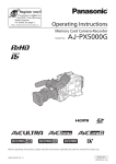
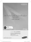
AEX060EDEHA
Air to Water Heat Pump
Outdoor Unit
installation manual
imagine the possibilities
Thank you for purchasing this Samsung product.
To receive more complete service, please
register your product at
www.samsung.com/register
E S F I P D DB68-03338A-1