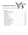
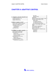
1
IP-Stile
KT-02
User Guide
IP-Stile
KT-02
User Guide
CONTENT
1 APPLICATION_________________________________________________3
2 MAIN FEATURES______________________________________________3
3 DESIGN_____________________________________________________4
4 OPERATION _________________________________________________7
4.1 Operation conditions_______________________________________7
4.2 Safety measures__________________________________________7
4.3 Power-up________________________________________________8
4.4 KT-02 operation__________________________________________8
4.5 Operation by remote control panel____________________________9
4.6 Operation by readers_____________________________________12
4.7 Operation by PC_________________________________________12
4.8 Operating principle_______________________________________12
5 Emergency actions____________________________________________14
5.1 Emergency exit by use of anti-panic barrier arms_______________14
5.2 Mechanical unlocking_____________________________________14
6 DELIVERY SET_______________________________________________15
7 TRANSPORTATION AND STORAGE_______________________________16
8 MARKING___________________________________________________16
9 TECHNICAL SPECIFICATIONS___________________________________17
10 OPTIONAL DEVICES AND MOUNTING HARDWARE_________________19
11 WARRANTY AND AFTER-SALES SERVICE_________________________20
User Guide
Dear Customer,
Thank you for purchasing PERCo IP-Stile. Please follow instructions given in
this Manual carefully, and this quality product will provide many years of troublefree use.
This Manual contains information that is necessary for comprehensive use of
capabilities of the IP-Stile by the checkpoint operator.
Abbreviations adopted in the Manual:
• ACS — access control system;
• KT-02 IP-Stile - entrance control system;
• RC — remote control panel.
1 APPLICATION
The KТ-02 IP-Stile (henceforth KT-02) is designed for control of
access to a facility by means of proximity cards under authorized/
nonauthorized principle and event logging in nonvolatile memory.
Install one KT-02 per each 500 people working the same shift, or on the basis
of the maximum throughput capacity 30 passages per minute.
2 MAIN FEATURES
• KT-02 can operate by the following devices:
• remote control panel;
• wireless remote control;
• readers (when an access cad is presented);
• PC (connected to local area network).
• KT-02 housing is powered with safe voltage.
• KT-02 has low power consumption.
• Inbuilt optical
registration in ACS.
arm
rotation
sensors
ensure
accurate
passage
• An inbuilt mechanical release lock ensures safe emergency unlocking of KT02 with a key (providing free rotation of the barrier arms).
• The KT-02 housing end faces are provided with visual indication modules.
• The housing contains two readers of proximity cards.
• Interrogation zones of the readers share location with the indication
modules.
3
KT-02 IP-Stile
3 DESIGN
to power
supply
to wireless remote
control
to LAN
Figure 1 – KT-02 design :
Standard delivery set:
– 1 — frame; 2 — base; 3 — top cover; parts 1-3 make housing; 4 — top cover lock;
– 5 — barrier arm, 6 — cap to cover barrier arms adjusting points; 7 — mechanical
release lock; 8 —indication module; 9 — control panel; 10 — control panel cable;
*Not included in standard delivery set:
– 11 — power cable; 12 — wireless remote control cable;
– 13— LAN connection cable.
4
User Guide
KT-02 consists of a housing with an inbuilt controller and two readers,
three barrier arms and a remote control panel (ref. Figure 1, parts 1-3, 5 and
9). After each passage through KT-02 the barrier arms are automatically
reset in the home position.
For visual informing on current KT-02 status both housing end faces
are equipped with indication modules. An access card reader is built-in
inside the housing under each indication module.
The indication module features three visual indicators (ref. part 8 in Figure 1
and Figure 2):
– the green light ( а ) indicates that the passage is authorized;
– the amber light ( b ) indicates that card presentation is expected;
– the red indicator (c) indicates that the passage is denied.
a→
b→
c→
Figure 2 – Visual indicators of the indication module
5
KT-02 IP-Stile
The remote control panel is connected to the housing with a
cable (ref. parts 9-10 in Figure 1 and Figure 3) and features:
– three buttons for setting KT-02 operating modes;
– t h r e e l i g h t i n d i c a t o r s ( t w o g r e e n a b o v e t h e s i d e b u tt o n s a n d
o n e g r e e n i n d i c a t o r a b o v e t h e m i d d l e b u tt o n ).
The left and right side
for unlocking KT-02 in the
in thee left direction, the
middle button (henceforth
through KT-02.
buttons (henceforth the «GO» buttons) are
corresponding directions: the left button —
right button — in the right direction. The
the «STOP» button) is for denying passage
KT-02 operation by the remote control panel, indication on the RC and
the indication modules according to KT-02 operating modes are described
below in section 4.
KT-02 is connected by cables to a power supply unit, an wireless remote
control device (if applicable, ref. Section 10 below) and to a local area
network (ref. parts 11-13 in Figure 1).
«GO» left side button
«STOP»middle button
«GO» right side button
Figure 3 – Remote control panel
6
User Guide
4 OPERATION
4.1 Operation conditions
KT-02 operation is allowed at ambient temperature from +1 °C
to +40 °C and relative air humidity up to 80% at +25 °C.
KT-02, with regard to environmental exposure, conforms to GOST
15150-69, category NF 4 (operation in premises with climate control).
DO NOT allow:
• KT-02 tugging, jerking or thumping;
• moving bulky goods through the passageway that exceed its width;
• dismantling and adjusting KT-02 operational parts except for the
maintenance work and troubleshooting specified in the KT-02 Assembly &
Operation Manual;
• cleaning the product with substances that may cause damage or corrosion.
4.2 Safety measures
When operating KT-02, always observe general safety requirements for use of
electrical equipment.
DO NOT use KT-02:
– when operation conditions don't conform to those given in the section 4.1;
– when the supply voltage differs from that given in the section 9.
The power supply operation should be carried out according to safety
requirements in its in-line documentation.
4.3 Power-up
Make
sure
all
the
connections
are
correct
(ref.
KT-02
Assembly & Operation Manual, sections. 8.4.5-8.4.6). Make sure the barrier
arms are in the home position (the passageway is blocked by a barrier arm).
Make sure the mechanical release lock is closed (KT-02 is mechanically locked,
ref. section 5.2). Connect the power supply to the mains with electric parameters
as per its documentation.
7
KT-02 IP-Stile
Turn the power on. At the first power-up while KT-02 is not yet
configured,all the three indicators of the indication modules are blinking
and the red indicator above the STOP button is on. After configuration and
subsequent power-ups the indication will reflect the corresponding
operating modes as currently set by the PC or the remote control panel
(ref. sections 4.4-4.7).
4.4 KT-02 operation
KT-02 as an access control system (ACS) component can be operated by the
remote control panel, a wireless remote control device, readers (when an access
card is presented) or by a PC connected to a local area network.
Each KT-02 passage direction features the following operating
modes (set from the computer):
• «Open» — KT-02 is unlocked in the authorized direction,
pressing of the remote control panel button responsible for this
direction is ignored;
• «Control» — KT-02 is locked in the corresponding direction,
pressing of the remote control panel button responsible for this
direction or presentation of an access card authorized for passag e
results in unlocking of KT-02 in this direction for a time set during
the system configuration;
• «Closed» — KT-02 is locked in the corresponding direction,
pressing of the r emote control panel button responsible for this
direction is ignored; whatever access card is presented, the system
registers an event of an authorized access attempt.
4.5 Operation by remote control panel
KT-02 operation by the remote control panel is available if the
«Control» mode is set on the PC. Setting of KT-02 operating modes and
the corresponding indication are given in Table 1.
8
User Guide
Table 1
KT-02 operating modes
№
Operating
mode
Actions by the
Operator
RC indication
Turnstile
indication
KT-02 status
«Always
locked» (KT02 is closed Press the Stop The red
1
for both
button shortly indicator is on
entrance and
exit)
The barrier
arms are
The amber
locked in the
indicators for
home position.
both directions The
are on
passageway is
blocked by the
barrier arm.
«Single
passage in
the set
direction
(KT-02 is
open for a
single
2 passage by
one person in
the set
direction and
closed for
passage in
another
direction)
The green
indicator
above the Go
button
responsible for
the authorized
direction is on
The green
indicator for
the authorized
direction and
th e amber
indicator for
another
direction are on
Both green
indicators are
on
The barrier
arms are
unlocked for
consecutive
single turns in
The green
each
indicators for
authorized
both directions
direction. After
are on
each turn the
arms are
locked in the
corresponding
direction.
«Bidirection
al single
passage»
(KT-02 is
3 open for a
single
passage in
each
direction)
Press shortly
the Go button
responsible
for the
authorized
direction
Press both Go
buttons
together
shortly
The barrier
arms are
unlocked for a
single turn in
the authorized
direction. After
the turn the
arms are
locked.
9
KT-02 IP-Stile
«Free
passage in
the set
direction»
(KT-02 is
open for free
4
passage in
the
authorized
direction and
closed in
another
Press shortly
the Stop button
together with
the Go button
responsible for
the authorized
direction
«Free
passage in
the set
direction
and a single
passage in
the
opposite
direction»
5
(KT-02 is
open fior free
passage in
the
authorized
direction and
a single
passage in
another)
Press shortly
the Stop button
together with
the Go button
responsible for Both green
the free
indicators are
passage
on
direction; then
press the other
Go button
shortly
«Free
passage in
both
directions»
6 (KT-02 is
open for free
passage in
both
directions)
10
Press shortly
the three
buttons
together
The green
indicator
above the Go
button
responsible for
the authorized
direction is on
The green
indicator for
the authorized
direction and
the amber
indicator for
another
direction are on
The barrier
arms are
unlocked
indefinetly for
multiple turns
in the
authorized
direction
The barrier
arms are
unlocked
indefinitely for
multiple turns
in the free
passage
direction and a
single turn in
the single
passage
direction
The barrier
arms are
The green
Both green
unlocked
indicators for
indicators are
indefinitely for
both directions
on
multiple turns
are on
in both
directions
User Guide
Features of operating modes setting
– the passage directions are independent of each other, i.e. setting an
operating mode in one direction does not change an already set operating
mode in another;
– the "Single passage in the set direction" operating mode can be
changed for the free passage in the same direction or the "Always
locked" mode;
– the "Free passage in the set direction" can only be changed for
the "Always locked" mode;
– after power-up, the KT-02 is reset in the "Always locked " operating
mode (the mechanical release lock is closed);
– in the single passage modes KT-02 will be closed as soon as a single
passage in the authorized direction is completed;
– if the passage is not completed within the passage waiting time, KT-02 is
automatically locked; the passage waiting time countdown starts since the
moment of pressing the authorizing Go button. The passage waiting time is
preset by the software during the configuration, the default setting being
4 seconds;
– when passage is authorized for both directions, after one passage is
completed, the passage waiting time countdown for another direction starts;
– if KT-02 receives control commands by stand-alone devices and ACS
simultaneously, a higher priority command will be executed. Priority of command
in descending order: by reader - by PC - by remote control panel.
4.6 Operation by readers
For KT-02 operation by inbuilt readers with access card presentation it is
necessary to enter the card list into the software. This allows arrangement of
access control to the facility under authorized/non-authorized principle and
event logging in the controller nonvolatile memory.
The access card should be presented by taking it to the reader's interrogation
zone (ref. Figure 5). When the presented access card is operable and valid at the
moment of the passage, KT-02 is unlocked the green GO indicator on the side
where the card is presented goes. After completion of the passage KT-02 and the
indication return to the reset state.
When an access card not entered in the list is presented, the red indicator on
the side of the presentation goes on, the audio signal sounds, KT-02 is not
unlocked; the indication returns to the reset state in 3 seconds.
11
KT-02 IP-Stile
4.7 Operation by PC
LAN connected KT-02 operation by PC is undertaken as per PERCo-SL01
Software Operation Manual.
4.8 Operating principle
When the «access authorized» signal is given (by the remote control
panel, wireless remote control, a reader or PC) the barrier arma are unlocked
and passage in the authorized direction is available.
When the barrier arms rotate 67°, KT-02 registers a passage event in
the corresponding direction.
In the single passage mode, after the barrier arms rotate 67° ( or the time
since the moment of pressing the GO button exceeds the passage waiting
time, ref. section 4.5), passage in this direction closes (a 53° reset of the
barrier arms is available to complete the passage) and KT-02 is ready to
execute the next command.
In the always free mode, after the barrier arms rotate 67°, passage in
this direction remains open.
When the barrier arms return in the home position (the barrier arms have
rotated 112°), KT-02 is registered as returned to the reset state.
12
User Guide
5 Emergency actions
5.1 Emergency exit by use of anti-panic barrier arms
An additional emergency exit can be arranged by means of anti-panic
barrier arms. The design of the barrier arms enables arranging of a free
escape passage without any special means or tools.
To make the passageway free, just pull the horizontal barrier arm along its
axis outwards the hub until released, then fold the arm down (ref. Figure 4).
Figure 4 — Anti-panic barrier arms operation
5.2 Mechanical unlocking
The mechanical unlocking feature is designed for unlocking the barrier
arms in case of emergency, e.g. if the power supply is down.
Proceed as follows to mechanically unlock KT-02:
-insert the key into the mechanical release lock (part 7 in Figure 1);
-turn the key clockwise until it stops (open the lock, thе lock internal
mechanism moving out);
-make sure KT-02 is unlocked by manually rotating the barrier arms a few
turns in each direction.
13
KT-02 IP-Stile
To lock KT-02 mechanically:
- set the barrier arms in the home position;
- press the internal lock mechanism recessing it into the housing until it
clicks;
- make sure KT-02 is locked and the barrier arms can not be rotated in
either direction.
6 DELIVERY SET
KT-02 is packed in a transportation box for its protection against
damage during transportation and storage.
Box overall dimensions (L х W х H) — 1120х720х350 mm.
Maximum gross weight of the boxed KT-02 is 42 kg (standard delivery set).
Box contents:
– IP-Stile housing..............................................................................1
– barrier arms...................................................................................3
– Remote control panel with cable.............................................1
– mechanical release key...................................................................2
– key to housing cover lock...............................................................2
– jumper..........................................................................................1
– stop spring ...................................................................................2
– self-adhesive wire retainer..........................................................3
– fixing tape 100 mm.....................................................................6
– insulation bushing..........................................................................2
– plug ∅30 mm..............................................................................6
– Certificate......................................................................................1
– KT-02 Assembly & Operation Manual...............................................1
– KT-02 User Guide.......................................................................1
7 TRANSPORTATION AND STORAGE
KT-02 in the original package should be transported in closed freight
containers or other closed type cargo transport units.
During storage and transportation the boxes can be stacked no more than 4
layers high.
14
User Guide
The storage of the product is allowed indoors at ambient temperature from
– 25 °C to + 40 °C and relative air humidity up to 98% at +25 °С.
After transportation or storage at temperatures below zero or in high air
humidity, prior to the installation the product must be kept unpacked for no less
than 24 hours indoors in the climate conditions as per section 4.1.
8 MARKING
The KT-02 marking label is placed inside on the back of the housing.
When it is necessary to access the label reading the inbuilt controller
elements, remove the top cover (see part 3 in Figure 1) taking the
following steps:
- turn KT-02 power off;
- insert the key into the top cover lock (part 4 in Figure 1), turn it
clockwise until stop and open the lock (thе lock internal mechanism will
move out together with the latch);
- holding the back edge of the cover with one hand, lift the front edge
gently by another — the cover must turn relative to the inside hooks.
Remove the cover carefully making sure not to damage the controller
underneath;
- lay the cover on an even steady surface.
Make sure the cover is returned in its operative position observing all
the mentioned precautions. When the cover is on, close the cover lock
pressing on the internal mechanism and recessing it into the housing until
it clicks. Turn the power on for KT-02 to continue operation.
KT-02 standard delivery set (ref. section 4.1) is packed in a
transportation box for protection against damage during transportation and
storage.
15
KT-02 IP-Stile
9 TECHNICAL SPECIFICATIONS
Operational voltage_______________________________________12±1,2 V DC
Maximum power consumption_____________________________________15 W
Throughput capacity in single passage mode______________30 persons/min
Throughput capacity in free passage mode________________60 persons/min
Passageway width____________________________________________550 mm
Maximum barrier arm rotation force______________________________3,5 kgf
Number of readers__________________________________________________2
Minimum card reading range at the nominal operational voltage:
EM-Marin cards__________________________________________________6 cm
Number of inputs:
remote control______________________________________________________3
testing____________________________________________________________2
Number of outputs:
relay (relay outputs NC, С and NO)___________________________________2
“open collector” type________________________________________________2
Communication interface standard__________________Ethernet (IEEE 802.3)
Number of users (access cards)
KT-02 1-01__________________________________________up to 10000 cards
KT-02 2-01__________________________________________up to 50000 cards
Event memory capacity
KT-02 1-01_________________________________________up to 10000 events
KT-02 2-01_________________________________________up to 50000 events
RC cable length_____________________________________no less than 6.6 m
RC overall dimensions (L x W x H)________________________127х84х30 mm
Maximum RC net weight_______________________________________0,35 kg
Electric shock protection class _____________III under GOST R IEC 335-1-94
Minimal mean time to failure_________________________2,000,000 passages
Mean lifetime_________________________________________________8 years
Overall dimensions with barrier arms (LxWxH),_________640х683х1040 mm
Maximum net weight____________________________________________35 kg
16
User Guide
The inbuilt controller has a unique physical address designated at the
production stage (MAC-address given on the label on the circuit board), as well as
an IP- address (given on the label on the processor microchip), a subnet mask
(255.0.0.0), a gateway IP-address (0.0.0.0). The controller supports updating of
the embedded software through the local are newtwork.
KT-02 overall dimensions are given in Figure 5.
reader's
interrogation zone
Figure 5 – KT-02 overall dimensions
17
KT-02 IP-Stile
10 OPTIONAL DEVISES AND MOUNTING
HARDWARE
The following optional devices and mounting hardware can be used
with KT-02 (supplied to customer order):
• power supply;
• intrusion detector and siren (used only when KT-02 operates as part
of the PERCo-S-20 system);
• wireless remote control (consisting of a receiver and two transmitters
with operating range up to 40 m).
The wireless remote control device can be connected to KT-02:
– instead of the remote control panel;
– together with the remote control panel (parallel connection).
When wireless control is used, the receiver is connected to KT-02 with cable
(part 12 in Figure 1). KT-02 operation by wireless remote control is similar
to operation by the remote control panel: the buttons of the receiver tags
perform the same functions as the buttons of the remote control panel (ref.
section 3 above).
Parallel connection of wireless remote control and the control panel may
lead to signal overlapping and KT-02 will respond to the resulting
combination of output signals accordingly.
11 WARRANTY AND AFTER-SALES SERVICE
Warranty terms and technical support contact information are given in
the certificate to KT-02.
18
PERCo
Postal address:
P.O. Box 87,
Saint Petersburg, 194295,
Russia
Tel: +7 (812) 329 8924, +7 (812) 329 8925
Fax: +7 (812) 516 4876
[email protected] (product and price information)
[email protected] (technical support)
www.percoweb.com
www.perco.ru