1
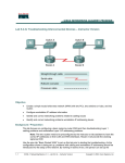
Lab 5.2.3c Troubleshooting Interconnected Devices Objective • Create a simple routed wide-area network (WAN) with two PCs, two switches or hubs, and two routers • Configure workstation IP address information • Identify and correct networking problems related to cabling issues • Identify and correct networking problems workstation IP addressing issues Background / Preparation This lab focuses on configuring a basic router-to-router WAN and then troubleshooting Layer 1 cabling problems and workstation Layer 3 IP addressing problems. Note: The two routers need to be preconfigured by the instructor or lab assistant to have the correct IP addresses on their LAN and WAN interfaces. Router A will provide the clocking signal as DCE. Use the prior lab “Basic Routed WAN” to set up this lab prior to starting the troubleshooting. As the configuration shown is being set up, problems with cabling and workstation IP addressing should be introduced into the setup of the network. By working in teams of two, one person can set up the 1-3 CCNA 1: Networking Basics v 3.1 - Lab 5.2.3c Copyright 2003, Cisco Systems, Inc. configuration and introduce some errors, and the other person can troubleshoot the setup to determine the problems. The equipment needed in this lab is the following: • Two Ethernet 10BASE-T or Fast Ethernet switches or two hubs • Two routers with an RJ-45 Ethernet or Fast Ethernet interface (or an AUI interface) and at least one serial interface. • 10BASE-T AUI transceiver (DB-15 to RJ-45) for a router with an AUI Ethernet interface, which is a 2500 Series • Several straight-through, crossover, and improperly wired or bad cables for connecting the workstations and routers to the hub or switch • One female (DCE) and one male (DTE) V.35 cable for interconnecting the routers Step 1 Set up the lab configuration for Team member A by doing the following: a. Set up the lab according to prior lab “Building a Basic Routed WAN”. b. As the components are being connected, use a variety of Category 5 cables including at least one crossover cable and a cable that is improperly wired. c. When configuring the workstations, introduce at least one misconfiguration of IP address information per PC. d. Record the problems introduced in the table below. Space is provided for up to three cabling problems and three IP problems. If it is a cabling problem, indicate the location of the problem, such as PC-A to Switch-A. If it is an IP related problem, indicate which PC the problem is with. In the third column, describe the problem introduced, such as crossover cable used, wrong IP address or wrong default gateway. Type of problem Location of problem Problem introduced Cabling related Cabling related Cabling related IP related IP related IP related Step 2 Troubleshoot the lab configuration for Team member B a. Check workstation to workstation connectivity. Ping from the command prompt on workstation A to the IP address of workstation B. If problems have been introduced, the ping attempt should fail. b. Check physical layer integrity. Start with Layer 1 issues and check the cabling between the PCs and the switch. Check for the proper type of cable as well as good connections. Check the cabling between the routers and the switches for connections. Replace cables and insure good connections as necessary. c. 2-3 Check network layer integrity. CCNA 1: Networking Basics v 3.1 - Lab 5.2.3c Copyright 2003, Cisco Systems, Inc. Check for Layer 3 configuration problems with the workstations. Note that the router should be preconfigured and should not have the problems that are introduced. Use the command prompt and the command winipcfg (Windows 95/98/ME) or ipconfig (Windows NT/2000) to check the IP configuration of each workstation. Control panel network application may also be used to check IP settings. Verify the IP address subnet mask and default gateway for each workstation. Step 3 Record problems found in the table below. This should be done by Team member B. Type of problem Location of problem Corrective Action Taken Cabling related Cabling related Cabling related IP related IP related IP related Step 4 Team members A and B switch roles and repeat the lab Step 5 Restore the PCs to their original IP settings, disconnect the equipment, and store the cables 3-3 CCNA 1: Networking Basics v 3.1 - Lab 5.2.3c Copyright 2003, Cisco Systems, Inc.