1
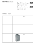
Operating Instructions
Direkt driven centrifugal fans
(Translation of the Original)
BA-RZA 6.3 – 09/2010
RZA
EN
Contents
1. Important information
2. Safety notes
3. Technical description
4. Transport
5. Mounting / Installation
6. Commissioning
7. Upkeep / Maintenance
8. Faults
9. Service
EC-Declaration of incorporation
EC-declaration of conformity
Further languages on request!
1. Important information
Nicotra Gebhardt Fans are “state of the art“ design and comply with the requirements for
health and safety of the EU Machinery Directive.
Nicotra Gebhardt fans offer a high level of operational safety and a high standard of quality
which is guaranteed through a certified Quality Management System (EN ISO 9001).
All fans are tested before leaving the factory and are provided with a test seal.
However, all fans can be dangerous:
• if they are not installed, operated and maintained by trained personnel;
• if they are not used for approved applications;
this can endanger the life and limbs of personnel, cause material damage to buildings and
equipment, and affect the life of the product.
Attention!
These Operating Instructions must be read and observed by all personnel engaged
in works involving fans.
The Operating Instructions
• describe the approved applications for the fans and protect against misuse
• contain safety notes which must be closely observed
• warn of dangers which can exist even with correct applications
• give important information on safety and the economic use of the fan whilst ensuring the
full benefits of the product are available
• are to be complemented with the trade and national Standards, Regulations and
Directives.
EN-2/16
Nicotra Gebhardt accepts no responsibility for damage or breakdowns that can be
traced back to non-compliance with the Operating Instructions.
The manufacturer’s guarantee does not apply following unauthorised conversions and
alterations to the fan.
No responsibility is accepted for resultant damage!
2. Safety Notes
This symbol identifies all safety information concerning danger to life and limbs of
personnel.
This symbol draws attention to the information in the Operating Instructions which
must be complied with in order to ensure correct working procedures, as well as
preventing fan damage and destruction.
3. Technical description
3.1
Product description RZA
The rotavent series of centrifugal fans, with double inlet and low-slip direct drive integral
motors in the fan airstream, are suitable for the transport of dust-free air and other nonaggressive gases or vapours.
The scroll casing, which is not gas-tight, is made of galvanised sheet steel and is provided
with flange connections at the outlet.
The powder-coated centrifugal impeller with backward curved hollow profile blades is
attached directly to the rotor of the integral motor.
The integral motors are designated as having protection class IP 54 and heat class F.
To prevent overloading, Positive Temperature Coefficient (PTC) are inserted in the
windings of the motors. In conjunction with PTC release equipment or a frequency inverter
with PTC connection, effective motor protection is guaranteed.
If the motor is to be set up outdoors or if very damp air is to be moved, then a condensation
drain plug - available as an accessory - should be inserted in the lowest point of the casing.
1. Fan
Important accessories
2. Inspection cover
3. Condensation drain plug
4. Inlet guard
The fans are intended for incorporation into equipment and do not have either their
own contact protection nor an earthed metal casing fitted as standard. The
appropriate protective measures against contact must be taken in accordance with
DIN EN ISO 12100 and earthing in accordance with DIN VDE 0100.
EN-3/16
3.2
Technical Data
Technical data and the permissible limits are to be taken from the type plate, the technical
datasheets or the appropriate technical catalogue and must be adhered to.
3.3
Authorised use
The fans are intended for the transport of dust-free air and other non-aggressive gases or
vapours.
Permissible transport media temperatures:
Model
Temperature
RZA
-20°C ... +40°C
Any installation deviating from the above will be considered unauthorised. Nicotra
Gebhardt will not be responsible for any injury to personnel and/or material damage
resulting from any deviations from the above.
Wherever control engineering devices featuring electronic components (e.g.
frequency inverters) are used, the recommendations of the device manufacturer, as
well as our wiring instructions and recommendations for cables and connections
(see Section 5.4), must be observed in order to prevent electromagnetic faults (EMC).
3.4
Improper use
Examples of an improper installation include:
• media with unacceptably high or low temperatures
• aggressive media.
• very dusty media.
The results would be:
bearing- and corrosion damage, loss of balance, vibration, deformation, abrasion damage.
Unauthorised operation
• No operation above the indicated rpm (see type plate, data sheet)!
• No operation at rpm ranges with increased vibration (resonance)!
• No operation at rpm ranges out of permitted fan curve area (stability of flow pattern)!
• No operation if fan becomes polluted!
Danger points:
Injury to personnel and material damage can result from impeller breakage, shaft
breakage, fatigue failure and fire from spark creation.
EN-4/16
4. Transport
4.1
Transport damage
Deliveries are to be immediately checked as being intact and complete in the presence of
the carrier.
In the event of transport damage, the attached instruction leaflet is to be observed.
Fans must be carefully transported!
Improper transport, e.g. unsupported, tilted positioning, can lead to:
• the impeller becoming jammed
• the shaft becoming deformed
• bearing damage
4.2
Transport safety
• The transport material is to be selected according to the weight and packaging of the fan
(type plate, data sheet).
• Ensure that loading is carried out in accordance with the instructions.
• Four-point lifting is to be provided when transporting by crane (2 slings)
The attachment points are:
• packaging
• fan casing (slings)
The attachment points are not:
• motor supports
• inlet and outlet flanges
4.3
Intermediate storage
For intermediate storage of the fans the following points must be observed:
• The fan should be stored in its transport packaging; this can be added to in accordance
with external influences.
• The place of storage must be dry and dust free and must not have high humidity (<70%)
• max. permissible storage temperature: -25°C to +40°C.
EN-5/16
5. Mounting / Installation
5.1
Safety notes
• Mounting may only be carried out by trained personnel in accordance with these
Operating Instructions and with regard to the regulations in force.
• Safety devices that have been removed for mounting work must be replaced
immediately afterwards, and before the electrical connection is made.
• The fans must be mounted such that secure fixing is guaranteed at all times during
operation.
• Fans must be fixed to plinths or base frames.
Supporting the weight at other points leads to fan damage and is dangerous.
5.2
Installation site
• The installation site must be suitable for each fan with regard to type, composition,
ambient temperature and ambient medium (points 3.2, 3.3 and 3.4 should be observed).
• The supporting construction must be level and have sufficient bearing strength
• When installing outdoors or if very damp air is to be moved, a condensation drain plug available as an accessory - should be inserted in the lowest point in the casing.
5.3
Installing / Fixing
• The fan or base frame must be fixed without stresses to the supporting structure.
• In the case of the RZA series and for packaging reasons, the feet are mounted as
standard with the 90 casing position.
• Set up the feet in the desired position before final fixing.
Stresses can lead to bearing damage and fatigue failures. They also affect the
functioning of the fan.
• No forces should be transferred from other parts of the plant.
• Use flexible connecting supports for duct connection.
• Ensure even spring of the vibration dampers.
5.4
5.4.1
EN-6/16
Electrical connections
Safety notes
Attention!
The rotor is fitted under electrically isolated conditions i.e. without earthing. Before
coming into contact with the impeller the fan has to be switched off the power or
from the inverter.
The spiral casing has not been earthed at the factory!
The customer must take appropriate steps in accordance with DIN VDE 0100!
• The electrical installation of the fan and components must only be carried out by trained
specialists in accordance with these Operating Instructions and with regard to the
effective regulations, as well as the Operating Instructions of the frequency inverter.
• The following Standards and guidelines are to be observed:
o IEC 60364-1 / DIN VDE 0100; DIN EN 60204-1
o EMC guidelines
o the regulations of the local Electricity Supply Company
• Equipment in accordance with EN 60204-1 is to be installed as protection during
unexpected events (e.g. an isolation switch for inspections).
5.4.2
5.4.3
5.4.4
Motors
The specially developed low-slip integral motors are designated as having protection class
IP54 and heat class F. They are optimised to a high rate of efficiency, with speed that can be
adjusted between 0 and 100% via the frequency inverter.
The motors are fitted with an easily accessible metal clamping box.
The motors meet the interference immunity requirements of EN 50082-2. Operation with a
frequency inverter can, depending on the inverter design (different types feature different
interference suppression measures), result in varying interference emissions. When operating
with motor / frequency inverter, the EMC instructions of the frequency inverter manufacturer
(see Operating Instructions) must be observed in order to meet the permissible limit as per
EN 50081-1. The motors are designed for S1 continual operation. With more than three starts
per hour the suitability of the motor is to be confirmed by Nicotra Gebhardt.
Motor protection
To prevent overloading, PTC are inserted in the windings of the motors. In conjunction with
PTC release equipment or a frequency inverter with PTC connection, effective motor
protection is guaranteed.
Motor connections
Attention!
The motors ex works are in star connection (Y). When operating with a frequency
inverter, the links must be placed in delta connection (Δ) (see wiring diagram).
The fans are supplied in a ready-to-install state, and are fitted with an easily accessible
metal terminal box.
Each fan comes supplied with a terminal board wiring diagram (in the lid of the terminal
box), showing the correct connection.
The following information must be observed when operating with a frequency
inverter.
5.4.5
Operation with frequency inverter
Attention!
When connecting the frequency inverter, please observe the Operating Instructions
of the frequency inverter which is being used.
If frequency inverters are used on site, it must be ensured that the voltage steepness complies
with the directives of the IEC TS 60034-17 :2002 + corrigendum 2003 (maximum stress limit of
the permitted pulse voltage). Depending on the frequency inverter being used and the line
length between the frequency inverter and integral motor, additional devices (e.g. motor
throttle, active sinus filter) must be provided to enable the specified permissible limits to be met.
Non-observance of this can lead to destruction of the motor!
EN-7/16
5.4.6
Parameters of the MM420 frequency inverter
When operating with a frequency inverter with rated voltage of 400V, the effective
cut-off frequency must be set to 87Hz. The motor must then be in a delta connection
(Δ).
The output voltage of the frequency inverter in relation to the frequency is illustrated
for a quadratic voltage / frequency specification in the diagram opposite.
Motor
voltage
Frequency
311
700
1000
1080
1082
1120
1121
3900
MM420 3AC 400V 5.50kW
EMV B ID.-Nr. 119914
MM420 3AC 400V 7.50kW
EMV B ID.-Nr. 119915
MM420 3AC 400V 7.50kW
EMV B ID.-Nr. 119915
MM420 3AC 400V 11.0kW
EMV B ID.-Nr. 119916
0560-
MM420 3AC 400V 4.00kW
EMV B ID.-Nr. 119913
0500-
MM420 3AC 400V 2.20kW
EMV B ID.-Nr. 119911
0450-
MM420 3AC 400V 1.50kW
EMV B ID.-Nr. 119910
0280-
MM420 3AC 400V 1.10kW
EMV B ID.-Nr. 119909
310
Funktion
Quick Start
Nominal Motor Voltage
Current A
Nom. Motor Power kW
Nom. Motor Frequency
Hz
Speed 1/min
Command Source
Source of Nominal
Frequency
Min. Frequency Hz
Max. Frequency Hz
Start Lookup Time sec.
Response Time sec.
End Commissioning
Access Level
0250-
MM420 3AC 400V 0.75kW
EMV B ID.-Nr. 119908
Nr.
10
304
305
307
0225-
RZA 110315- 0355- 0400-
1
400
1,6
0,60
1
400
2,5
0,95
1
400
3,7
1,50
1
400
5,3
2,20
1
400
7,9
3,60
1
400
12,0
4,40
1
400
15,8
5,20
1
400
15,9
5,90
1
400
21,2
11,00
87
87
87
87
87
87
87
87
87
2510 2520 2540 2530 2530 2540 2520 1700 1660
1-Console, 2-Jumperboard
1-Keyboard set point, 2-Analog input, 3-Fixed frequency, 12-Analog
input+Keyboard
0
0
0
0
0
0
0
0
0
110
110
100
95
90
80
70
90
87
> 30
> 30
> 30
> 30
> 30
> 30
> 30
> 30
> 30
> 30
> 30
> 30
> 30
> 30
> 30
> 30
> 30
> 30
1
1
1
1
1
1
1
1
1
3
2
2
2
2
2
2
2
2
2
701Motor Protection
after connecting 5, 6 or 7, the parameter of P0701, P0702 or P0703 must be 29
3
Voltage/Frequency
1300
2
2
2
2
2
2
2
2
2
Curve Square
2000 Reference Frequency
110
110
100
95
90
80
70
90
87
For secure operation of our RZA-Fans with Micromaster*, there are following Settings
required after quick start.
Also note next pages!
EN-8/16
Connection diagram for frequency inverter
Fn
Jog
P
1/3 AC 200V ... 240V
3 AC 380V ... 480V
PE
FS1
PE
+
–
1
2
4.7 k
AIN+
AIN-
DIN1
DIN2
DIN3
+
–
24V
+10 V
0V
3
4
A
D
max. 33V
max. 5mA
5
6
7
8
9
AC
DC
+
+24V (max. 100mA)
0V*
–
CPU
RL1
RL1-B
RL1-C
L, N (L1, L2)
L1, L2, L3
+
DC
10
11
AC
AOUT+
AOUT-
P+
N-
12
13
A
D
14
15
RS-485
PE
U, V, W
M
3~
2
DIN4
24V
+
0V
3
4
–
9
0V*
* (potential separation)
Power supply and analogue input Input voltage: 0V to +10V, scalable
Power supply
Output relay contact AC 250V, max. 2A (inductive load) DC 30V, max. 5A (ohmic load)
Analogue output 0mA to 20 mA
If a communications module is connected then the serial interface is ineffective!
To get an additional digital input (DIN4), the circuit must be changed as shown in fig. Control panel (accessory)
Intermediate circuit connection
EN-9/16
5.4.7
Wiring instructions for type MM420 frequency inverter
To ensure that the directives of the IEC TS 60034-17:2002 + corrigendum 2003 (maximum
stress limit of the permitted pulse voltage) are complied with, the following instructions must
be adhered to under all circumstances.
• Keep the cables short!
• Apply cable screening over a large surface area.
• Keep the number of contact points between the inverter and fan to a minimum,
preferably direct from the frequency inverter to the motor terminal box!
• Caution when using bypass operation! Dynamic transient phenomena may arise here. If
absolutely necessary, only switch off if currentless, i.e. first revoke the release of the
inverter and then open the motor cables! (See also point 4 –relays are also additional
connecting points)
Also be sure to observe the following wiring requirements:
• Screened cables in accordance with EMC guidelines must be used between the filter
and frequency inverter and between the frequency inverter and motor.
• The protective earth conductors must be fitted in addition to the screened cables.
• Cables longer than 20m require a motor inductor between the frequency inverter and
motor (available on request).
• Control cables and motor cables must be installed separately and, where necessary, be
crossed at 90°.
• The screened cables must be applied on both sides.
• A large area of the screened motor cable is to be attached to the motor’s terminal box
using a metal connection.
5.4.8
Motor protection with frequency inverter
For operation with the motor protection function using PTC, it is necessary to install a 1kΩ
resistor on site. This is to be connected in accordance with the wiring diagram and,
together with the PTC, serves as a voltage distributor
Control Clamps
8
Motor
PTC
5, 6 or 7
1 kΩ
9
Connection diagram
5.4.9
c Power fuse
d Circuit-breaker
e Power inductor
f Filter (class B only)
g Screen
h Frequency inverter
i Motor
g
c
EN-10/16
d
e
f
h
i
RZA 114x
0225-4D
7x
4x
0250-4D
7x
4x
0280-4D
7x
4x
0315-4D
7x
4x
0355-4D
7x
4x
0400-4D
7x
4x
0450-4D
7x
4x
0500-6D
7x
4x
0560-6D
7x
Recommendation for cable and PG connection
Recommended minimum cable and gland size in the following table on the basis of the
delivery range from Lapp-Kabel company, Stuttgart.
Necessary cable size has to be finally determined in consideration of different factors it
side (i.e. Cable lengt, way of laying …)
Connecting cable
Connecting cable
Connecting cable
FI Motor
Mains FI
FI PTC
ÖLFLEX®
Min. dia.
ÖLFLEX®
100 CY
100 CY
4 x 1,0 mm²
1,0 mm²
2 x 0,5 mm²
100 CY
100 CY
7 x 1,0 mm²
1,0 mm²
2 x 0,5 mm²
100 CY
100 CY
4 x 1,0 mm²
1,0 mm²
2 x 0,5 mm²
100 CY
100 CY
7 x 1,0 mm²
1,0 mm²
2 x 0,5 mm²
100 CY
100 CY
4 x 1,5 mm²
1,5 mm²
2 x 0,5 mm²
100 CY
100 CY
7 x 1,5 mm²
1,5 mm²
2 x 0,5 mm²
100 CY
100 CY
4 x 1,5 mm²
1,5 mm²
2 x 0,5 mm²
100 CY
100 CY
7 x 1,5 mm²
1,5 mm²
2 x 0,5 mm²
100 CY
100 CY
4 x 1,5 mm²
2,5 mm²
2 x 0,5 mm²
100 CY
100 CY
7 x 1,5 mm²
2,5 mm²
2 x 0,5 mm²
100 CY
100 CY
4 x 2,5 mm²
2,5 mm²
2 x 0,5 mm²
100 CY
100 CY
7 x 2,5 mm²
2,5 mm²
2 x 0,5 mm²
100 CY
100 CY
4 x 2,5 mm²
4 mm²
2 x 0,5 mm²
100 CY
100 CY
7 x 2,5 mm²
4 mm²
2 x 0,5 mm²
100 CY
100 CY
4 x 2,5 mm²
4 mm²
2 x 0,5 mm²
100 CY
100 CY
7 x 2,5 mm²
4 mm²
2 x 0,5 mm²
100 CY
100 CY
4 x 2,5 mm²
4 mm²
2 x 0,5 mm²
100 CY
100 CY
7 x 2,5 mm²
4 mm²
2 x 0,5 mm²
ÖLFLEX® is a registered trademark of Lapp-Kabel, Stuttgart
The connection box has 2 cable passage holes provided with a thread M 20x1.5. They are
provided for the main and the PTC lead (both shielded). The union pieces have to be
provided with enough contact surface for the cable shielding
EN-11/16
6. Commissioning
6.1
Safety checking
• Check that all mechanical and electrical safety devices have been fitted and connected.
• According to the type of installation of the fan, the inlet and discharge openings as well
as the drive shafts must be fitted with protection devices in accordance with DIN EN ISO
13857. The appropriate protection guards are available and should be ordered as
extras.
• If the surface temperature of accessible fan parts exceeds +70°C
(DIN EN ISO 13732-1), isolating protection devices must be fitted.
Before commissioning, the following checks must be carried out:
• The ducts and the fan must be checked for foreign bodies (tools, small components,
building debris, etc.)
• The free running of the impeller must be checked by hand.
• The power setting, voltage and frequency for the mains connections must be checked
against the fan or motor type plate.
• Connected control devices must be checked for functioning.
• Inspection openings (if they exist) must be closed.
Operation with a frequency inverter is only permissible in compliance with the
directives of the IEC TS 60034-17:2002 + corrigendum 2003 (maximum stress limit of
the permitted pulse voltage).
The fan may only be commissioned if all the safety devices have been fitted.
Ensure that the impeller has been secured acc. to DIN EN ISO 13857!
The suitability of protection devices and their fixtures to the fan have to be
evaluated within the complete security concept of the installation.
EN-12/16
6.2
Test run
The fan should be switched on briefly to check that the direction of rotation of the impeller
agrees with that indicated by the arrow.
In the event of the motor running in the wrong direction, the poles are to be changed over
whilst observing the electrical safety instructions.
6.3
Check the current consumption
Upon reaching the operating speed of the fan, immediately measure the current
consumption and compare it with the nominal current on the motor or fan type plate. In the
event of a substantial overcurrent, switch off immediately
6.4
Check for quiet operation
Check for quiet operation of the fan.
There should be no unusual rocking or vibration. Check for untypical bearing noises.
7. Servicing / maintenance
7.1
Safety notes
Before working on the fan it is imperative to ensure:
• The drive motor is separated from the mains on all poles. In the case of trouble
the rotor could be under current!
• The impeller has come to rest.
• The surface temperature has been checked to prevent burning.
• There is no possibility of an uncontrolled running of the fan during the
maintenance work (e.g. through an isolating switch).
• Any debris or dangerous materials which have arrived in the fan with the transported
medium must be removed using a suitable method.
• Fan operation may resume after the safety checks of Section 6 “Commissioning / Safety
checks” have been carried out.
• Only limited work may be carried out whilst in the operating condition and in observance
of the safety and accident prevention regulations: e.g. measurement of vibration.
Non-observance of these points endangers life and limb for the maintenance
personnel.
If the state of the fan does not allow adapted action for repair it has to be put out of
order immediately and to be replaced if required!
7.2
Maintenance intervals
After having passed the period during which the grease keeps it’s lubrication capacity
(30.000 h for standard applications) bearing are to changed.
During periods of longer lasting stand stills the fan may be operated shortly in regular
intervals. This is to prevent the bearings from mechanical load and the avoid ingress of
humidity. If fans have been hold on stock for a longer period the bearings of fan and motor
have to be checked prior to installation.
The maintenance instructions of the motor supplier as well as the instructions for
the switches and control units have to respected.
The fan has be checked regularly whether vibrations may occur. The maximum vibration
speed in radial direction must not exceed 4,5 mm/s to monitored at the bearing or bearing
housing of the fan or motor. For fans of a impeller diameter up to 315 mm a vibration speed
of up to 7,1 mm/s is acceptable.
A deposit of dust and solids can cause unbalancing and consecutive damages.
In order to prevent this danger regular inspection and cleaning operations are to be
scheduled.
If due to the type of media conveyed one can expect wear or dirt accumulation on the
housing (corrosion, abrasion, caked material) then regular inspection and cleaning must be
carried out.
The intervals will vary according to operating conditions and should be set by the operator.
EN-13/16
No high pressure cleaners (steam rod cleaners) are to be used.
7.3
Inlet and discharge accessories
Flexible sleeving (compensators) between the fan and plant parts are to be checked at
regular intervals.
Unsealed sleeving leads to breakdowns and danger from escaping transported
medium and must be replaced.
7.4
Spare parts
The RZA centrifugal fan is a proven, maintenance-free and long-lasting product of the
highest quality.
In the unlikely event of appliance failure, please contact our Customer Service Department
or return the complete fan to us.
For economic reasons, only complete fans can be replaced.
Nicotra Gebhardt accepts no responsibility for damage resulting from the use of
non-Nicotra Gebhardt parts.
8. Faults
Deviations from normal operating conditions always lead to functional breakdowns and
should be looked for immediately by maintenance personnel.
Recurring faults can result in the destruction of the fan and give rise to damage in
plant parts and injuries to personnel.
In the event that maintenance personnel cannot eliminate the fault, please contact our
Customer Service Department.
9. Service
We offer to all our partners the following services:
• Mobile Customer Service
• Spare Parts Service
Telephone
+49 (0)7942 101 384
Telefax
+49 (0)7942 101 385
E-Mail: [email protected]
www.nicotra-gebhardt.com
EN-14/16
EC-Declaration of incorporation
The manufacturer:
Nicotra Gebhardt
Gebhardtstrasse 19-25,
D-74638 Waldenburg, Germany
herewith declares, that the following product:
Productdesignation:
Type nomination:
Serial n°:
Year of production:
Centrifugal fan, direct driven
RZA
see type plate
see type plate
qualifies as a partly-completed machine, according to Article 2, clause “g” and does comply to the following
basic requirements of the Machine Directive (2006/42/EC): Annex I, Article 1.1.2; 1.3.7,1.5.1
This partly-completed machine must not be put into service until the final machinery into which
it is to be incorporated has been declared in conformity with the provisions of the Machine Directive
(2006/42/EC).
The following harmonised standards 1) have been applied:
DIN EN ISO 12100-1
Safety of machines – Fundamental terms, general design principles, Part 1:
Basic terminology, methods
DIN EN ISO 12100-2
Safety of machines – Fundamental terms, general design priciples, Part 2:
Technical principles and specifications
DIN EN ISO 13857
Safety of machinery - Safety distances to prevent hazard zones being
reached by upper and lower limbs
EN 60204-1
Safety of machines - Electrical equipment of machines, Part 1: General
requirements
Applied, national standards and technical specifications 2) particularly:
VDMA 24167
Fans – Safety requirements
The manufacturer is committing himself to make the special documents of partly-completed machine
available to any state authority if required.
Waldenburg, 22.09.2010
Head of Production
i.V. W. Weckler
1)
2)
Head of Research and Development
i.V. Dr. J. Anschütz
The complete listing of applied standards and technical specifications see manufacturer’s documentation
As far as harmonised standards are not existing
EN-15/16
EC-Declaration of conformity
to
EC- Directive of Electromagnetic Compatibility (2004/108/EG)
Herewith we declare that the machinery designated below, on the basis of its design and construction in the
form brought onto the market by us is in accordance with the relevant safety and health requirements of the
EC Council Directive as mentioned below.
If alterations are made to the machinery without prior consultations with us, this declaration becomes
invalid.
Productdesignation:
Type nomination:
Serial n°:
Year of production:
Centrifugal fan, direct driven
RZA
see type plate
see type plate
Relevant EC-Council Directive:
EC-Directive of Electromagnetic Compatibility (2004/108/EG
Applied harmonized standards, in particular:
EN 60204-1, EN 61000-6-4
Waldenburg, 22.09.2010
Head of Production
i.V. W. Weckler
Head of Research and Development
i.V. Dr. J. Anschütz
For the complete List of applied standards and technical specifications see the manufacturer’s documentation.
Nicotra Gebhardt GmbH
Gebhardtstrasse 19-25
74638 Waldenburg
Germany
Telephon +49 (0)7942 1010
Telefax +49 (0)7942 101170
E-Mail [email protected]
www.nicotra-gebhardt.com
EN-16/16