1
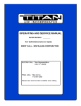
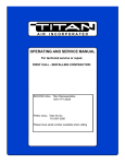
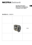
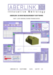
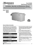
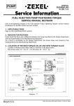
Operating Instructions EN
Industrial Process Fans
(Translation of the Original)
BA-IPF 14.5 – 08/2011
Contents
1. Important information
2. Safety notes
3. Technical description
4. Transport
5. Mounting / Installation
6. Commissioning
7. Upkeep / Maintenance
8. Faults
9. Service
EC-Declaration of incorporation
Further languages on request.
Revision Index
Revision
BA IPF 14.5 – 08/2011
EN-2/28
Amendment
Revision Index integrated;
Note „Dynamic loading of the impeller“;
Bearing lifetime 30.000 h reformulated;
Structure improved;
1. Important information
The Fans are of state of the art design and comply with the requirements for health and
safety of the EG Machinery Directive.
This Fans offer a high level of operational safety and a high standard of quality which is
guaranteed through a certified Quality Assurance System (EN ISO 9001).
All fans leave the factory after being subjected to testing and are provided with a test seal.
All fans however can be dangerous,
• if they are not installed, operated and maintained by trained personnel
• if they are not used for approved applications.
This can endanger the life and limbs of personnel, provoke material damage to buildings
and equipment and influence the use of the product.
Attention!
These Operating Instructions must be read and observed by all personnel engaged
on works involving fans!
The Operating Instructions
• describe the approved applications for the fans and protect against misuse. Supplementary instructions are available for fans featuring special equipment, e.g. axial face seals,
non-standard drives, etc.
• contain safety notes which must be closely observed.
• warn of dangers which can exist even with correct applications.
• give important information on safety and the economic use of the fan while ensuring the
full benefits of the product are available.
• are to be complemented with the trade and national Standards, Regulations and Directives.
Nicotra Gebhardt accepts no responsibility for damage or breakdowns which can be
traced back to non-observance of the Operating Instructions.
The manufacturer’s guarantee does not apply following unauthorised and unacceptable
conversions and alterations to the fan.
There is no responsibility accepted for resultant damages!
2. Safety Notes
This danger symbol identifies all safety and danger information concerning danger to
life and limbs of personnel.
This draws attention to all information at all points in the Operating Instructions
which must be particularly well observed in order to ensure the correct procedures
for the work as well as helping to prevent damage and the destruction of the fan.
EN-3/28
3. Technical description
3.1 Product description
Refer to annex „project sheet“
The fans are intended for incorporation into equipment and do not have their own
contact protection fitted as standard. The appropriate protection measures are to be
taken in accordance with EN ISO 12100!
Centrifugal fans with casing e.g.
direct drive
belt drive
direct coupling
Circulation fans without casing e.g.
direct drive
direct drive insulated
belt drive insulated
Exemplary construction elements on a sample fan with belt drive
6 1 3 5
1 contact protection
2 suction stub nozzle
3 housing
1
4 base frame
1,8,15
5 inspection cover
1,9,14
6 compensating connector
1
7 drain plug
8 cooling vane, heat block
12
9 bearing
10 impeller
6
11 motor
2
12 belt drive
13 Anti-vibration mounts
10
14 shaft
15 shaft seal
13 7
EN-4/28
4 11 9
3.2 Technical data
Technical data and the permissible limits are to be taken from the type plate, the technical
datasheets or the appropriate technical catalogue and must be adhered to.
3.3 Authorised use
Refer to annex „project sheet“ and signs attached to the fan as well as item 3.4.
Max. ambient temperature on drive motor: +40°C, if nothing otherwise is stated in the
„technical data“ of the fan.
Nicotra Gebhardt does not assume any liability from resulting injuries to persons
and/or damage to property!
Even when properly used fans and accessories may emit noises leading to hearing
damage or impairing communication. It must be considered that the noise level data
mentioned by Nicotra Gebhardt (refer to catalogue or „technical operating data“) may
change at the site owing to ambient conditions or resonances. If no Nicotra Gebhardt
noise suppression measures have been ordered, remedy by the customer may be
required.
If control equipment incorporating electronic components (such as frequency converters)
are used the recommendations of the equipment producer for avoiding electromagnetic
faults (EMV) must be adhered to (earthing, cable lengths, cable shielding etc.).
3.4 Improper Use
Improper use would be e.g. the transporting of:
• media with unacceptable high or low temperatures
• aggressive media without suitable fan sealing and material selection
• humid media apt to the creation of mould, without condensate socket and inspection
cover
• abrasive media without suitable wear protection
• Feed and circulating air with the production of foodstuff without the fan being foodfast
designed
• medium with inlet pressure that remained disregarded for the fan design (refer to „technical operating data“)
• installation in explosion-endangered areas without the fan and drive motor being suitably
equipped for such areas
• operation at speeds exceeding maximum rate.
• Explosion-proof devices, if no Atex certification from manufacturer is available.
Unauthorised operation
• No operation above the indicated rpm (see type plate, data sheet)!
• No operation at rpm ranges with increased vibration (resonance)!
• No operation at rpm ranges out of permitted fan curve area (unstability of flow pattern)!
• No operation if fan becomes polluted!
EN-5/28
Avoid dynamic load of the impeller.
No frequent alteration of load!
All application conditions not expressly verified by Nicotra Gebhardt (refer to technical
description) are considered unsuitable. In case of doubt inquire with Nicotra Gebhardt.
The consequences are e.g. as follows:
damaged bearings, corrosion damage, unbalance, vibration, deformation, abrasion damage, medium contamination.
The following are considered dangers: Personal injuries and damage of property
through broken impeller, broken shaft, impeller destruction, fatigue failure, fire from
created sparks or damage to the environment.
3.5 Vibration monitoring
Fans vital for operation, particularly fans for dust explosion applications, with high drive
capacity should be provided with a vibration monitoring unit if they are installed in soundreduced cabins or if the mode of operation lets expect unbalance (available against separate
order).
3.6 Fans for the transport of explosive gases
3.6.1 General
The process air fans for operation in explosive areas and / or for transportation of explosive
media comply with the regulation 94/9/EG (ATEX 95) and therefore conform, amongst
others, to the requirements of the following standards and directives: DIN EN 13463-1 and 5, EN 14986, EN 1127-1, EN 12100-1. In accordance with the above standards, the fans
comply with the requirements of Device Group II, ignition protection type “c” (constructional
safety) ), for transportation of group IIB gases as well as temperature classes T3 or T4 (G)
or T=125 °C (D). The category supplement “D” (explosive dust requirements) or “GD” (explosive gas and dust requirements) is possible as Nicotra Gebhardt process air fans meet
all requirements both for explosive gas and also explosive dust areas. A prerequisite for use
in explosive conditions is an inspection panel in thefan housing to allow the impeller and
internal surfaces to be cleaned.
Explosion protected fans are made of materials coated with stainless steel or are galvanized, as well as being made of stainless steel of quality V2A. Other stainless steel qualities
can be supplied on request.
Leakage in the fans of the ATEX models complies with the requirements of ISO 13349 of
leakage category D. (Leakage rate ≤0.162 l/(s*m2), with reference to the housing surface,
measured at a pressure difference of 2500Pa.
The model supplied by Nicotra Gebhardt (category and temperature class) can be
established from details on the relevant order confirmation and the type plate on the
fan. The details on the type plate and in the operating instructions must always be
observed.
EN-6/28
3.6.2 Identification and assessment
The identification of explosion protected fan models is carried out through the specification
of device group, category, ignition protection type and temperature class on the type plate
(for the interior and exterior of the fan respectively) as well as through the CE Ex mark by
which the conformity of the device with European directive 94/9/EG is confirmed. In addition
the technical documentation supplied with the fan also includes an EU declaration of conformity. Fans that are to be installed into a plant (series Q2M and P9M, in the housing
models “A”) comply with all the requirements of the above directive from a constructional
viewpoint, but cannot be identified by Nicotra Gebhardt with the CE Ex mark and category
details because they can only be completed once they have been installed as a functional
fan in a plant or machine. However, the data sheets enclosed with the product (including,
amongst others, “Notes on assessing installation fans in accordance with EU explosion
protection directive 94/9/EG”) allow the customer to carry out a conformity assessment as
well as a category and CE Ex identification after the proper installation, completion, checking for leakage and inspection of the fan in accordance with these operating instructions.
3.6.3 Instructions for safe operation in explosive areas
Compliance with the requirements of the above standards and directives and with
that ensuring safe operation in explosive areas and / or whilst transporting explosive
media assumes as a prerequisite that the following conditions are observed by the
customer or operator of the fan:
Essentially the following sources of ignition must be taken into account with our
fans:
• hot surfaces, e.g. through friction or a bearing seizing up or an impeller getting blocked
• sparks arising from blows, friction or rubbing, e.g. resulting from the contact of an impeller or rotating shafts with stationary components and air baffle units in the suction side
and pressure side compensator (s. a. section 7.5) for dust explosion
• spark formation through the discharge of electrostatically charged, non-conducting components, e.g. plastic surfaces, surfaces with strong film thickness.
• Both the manufacturer and operator of a machine or plant in explosive areas are
obliged to observe the appropriate standards and directives 94/9/EG (ATEX 95),
1999/92/EG3 (ATEX 137, operator guidelines).
Important notes!
• The instructions for transporting and storing (section 4), mounting and installation (section 5), commissioning (section 6) and the upkeep / maintenance (section 7) must be observed. The connection of pipes and air ducts must be gas leak-proof. The coating or
corrosion protection on the fans must be checked for suitability for the media with which
the fans are going to come into contact. Possible voltaic or chemical reactions must be
taken into consideration in this.
• Prior to commissioning ( s. a. section 6.1) the fan it must be ensured that the ignition
temperatures or temperature classes of the explosive transport or environmental media
correspond at a minimum to the temperature figures or class details on the type plate of
the fan.
• The collision of foreign bodies that get sucked or fall into the fan with the rotating parts of
the fan can create a substantial source of risk of ignition! Consequently the fans must be
equipped with protection against foreign bodies getting sucked in or falling in (at least
protection class IP 20) as well as prevention of mechanical influences from outside or
other damage.
EN-7/28
• Electrostatic charging of fans and their components can be a significant source of risk of ignition!
To protect against electrostatic charging the fans and the earthing terminal of the drive motor must
be connected to a suitable earth. Conductive parts, such as compensators, for example, must be
connected together with a suitable earth cable to the ground.
Generally, for applications in explosive areas, the elastic compensators and support
rings (plastic components) must only be cleaned by using a damp cloth, to avoid
electrostatic charging!
For category 2 + 3 conducting compensators and support rings are employed.
• Dust deposits on fans and their components can be a significant source of risk of ignition!
Particularly in the case of fans used in or for the transportation of dusty explosive media
(“Dust Ex”, category 2D resp. 3D) the instructions for upkeep and maintenance (section
7) must be carefully observed. The interior housing surfaces and impeller are accessible
for cleaning through an inspection panel.
When cleaning the fan components it is imperative to also remove dust deposits that
have formed in gaps between stationary and rotating parts (e.g. inlet cone / impeller, impeller hub / housing, shaft, shaft passage housing ) and on the drive motor.
• The lower operative range, volume flow rate of fan, is limited to the value indicated in the
characteristic curve. Operation is forbidden with lower volume flow rates!
Notse to vibrations
• Strong mechanical vibrations in fans and their components, caused by improper installation, and their components can be a significant source of risk of ignition! Fans used in or
for the transportation of dusty explosive media (“Dust Ex”, categories 2D) must be
equipped by the customer with a vibration monitor that allows the fan to be switched off
in good time if there are operational irregularities (e.g. vibrations that occur due to an imbalance through dust deposits or material being baked on the impeller). After being
switched off in this way, the fan must be properly cleaned prior to being put back into
service.
• Prior to commissioning and during maintenance work it should be checked whether the
smooth running of the fan has been impaired by transportation, installation or operation.
For this the vibrations at the bearings should be measured.
The following limiting values have been determined in accordance with ISO 14694,
application category BV-3 and must be kept to:
Condition
Run-up
Alarm
Switch off
Rigid assembly [mm/s r.m.s.]
4.5
7.1
9.0
Elastic assembly [mm/s r.m.s.]
6.3
11.8
12.5
• To protect the fan shaft bearings and the drive unit a vibration monitoring system (to be
installed by the client) is recommended.
EN-8/28
In the event of irregularities in operation, e.g. if unidentified noises should arise,
increased vibrations or high temperatures occur, the fan must be switched off immediately, the cause must be discovered and eliminated before the fan is put back into
service.
Check the gap dimension!
Any reduction in the permitted gap dimensions between static and rotating components (see table below) can present a significant source of risk of ignition! Prior to
commissioning and during maintenance work it must be ensured that the gap width
smin (see table below) is checked and that the fan is only put into operation if there is
no reduction in this minimum gap width.
In the case of fans made of stainless steel with a drive motor power in excess of
5.5 kW, the customer must carry out regular checks of the gap between stationary
and rotating components (e.g. between the impeller and housing). This can take the
form of a manual or continuous vibration check at the bearing points, for example,
that allows the fan to be switched off in good time if there are operational irregularities (e.g. vibrations that occur due to an imbalance or a housing deformation caused
by external factors).
[4]
[5]
[6]
[4] Cover plate
cone
[5] Inlet cone
[6] Gap dimension gauge
A gap dimension gauge is supplied together with the fan to enable the gap width
between the inlet cone and the impeller to be checked. The gauge must be introduced through the inlet opening with the U-shaped end between the inlet cone and
the impeller in such a way that the right-angled end with the bore (handle) points to
the centre of the impeller (insert the gauge parallel to the axis of rotation of the
impeller and do not tilt it!), see diagram below.
In order to check the gap dimension the gauge must be inserted at a minimum of
four points separated by approx. 90° around the circumference. The impeller must
be turned manually through at least one rotation at each of the checking points.
During the rotation of the impeller there must be no falling below the minimum gap
dimension between the static and rotating parts. The gauge must not jam, only a
light touch by the impeller during rotation is permissible! This check is intended to
ensure that any changes in the gap dimension, that may have arisen after the unit
was delivered, for example due to improper transportation or installation (see also
points 4 and 5, in particular 5.3) are detected and remedied and that the fan complies with regulations when it is taken into service.
If this check shows that the gap is too small, then first of all it must be checked and
ensured that the fan is undamaged, and secondly that it is mounted and connected
properly and stress-free.
Attention:
The gauge supplied is designed specifically for this particular fan and must only be
used for it! Prior to starting up the fan make sure that the gauge has been removed
and that it cannot be sucked in or will otherwise interfere with the operation of the
fan! Keep the gauge in a safe place for future maintenance work.
If fans are supplied with an enclosed loose inlet cone then the above inspection
instructions also apply once the inlet cone has been installed by the customer. In
this case it must also be ensured that the fan is put into operation only once the
minimum gap corresponds to the requirements specified in the table.
EN-9/28
The following figures for the minimum gap dimension and the cone overlap must
be adhered to.
ü
NW
[1] Impeller
[2] Inlet cone
[3] Gap dimension gauge
NW
D1
D2
smin
ü
EN-10/28
Nominal width (cone)
Internal diameter (cover plate cone)
External diameter (inlet cone)
Gap width to be guaranteed using reference gauge
Overlap
D1
Smin
125
100
2
140
112
160
norm
min
max
3
0
5
2
3
0
5
126
2
4
0
6
180
141
2
4
0
7
200
158
2
5
0
8
224
178
2
6
0
9
250
199
2
6
0
10
280
224
2.5
7
0
11
315
251
2.5
8
0
12
355
282
3
9
0
14
400
316
3.5
10
0
16
450
355
4
11
0
18
500
398
4
12
0
20
560
447
4.5
14
3
22
630
501
5
16
3
25
710
562
6
18
3
28
800
631
6.5
20
3
32
900
708
7.5
22
3
36
1000
794
8
25
4
40
1120
891
9
28
4
45
1250
1000
10
32
4
50
1400
1122
11.5
36
5
56
1600
1259
13
40
5
63
Notes to the fan
The fan and motor bearings are designed in accordance with DIN ISO 281-1 to have a
nominal useful life of at least 20,000 hours (category 3) or 40,000 hours (category 2). They
must be regularly monitored. In the event of irregular bearing noises or bearing temperatures the fan must be switched off at once, the bearings must be inspected and replaced if
necessary.
• Shaft seals must only be replaced by identical parts.
• Inlet, outlet and all other connection points and housing gaps must be equipped with
seals for category 2.
• Firm seating of the impeller and shaft or motor should be checked and ensured prior to
commissioning and during every fan maintenance action.
• Improper low or high temperatures of the fans and their components can be a significant
source of risk of ignition! The specified temperature range for the transport medium or for
the fan’s (-20°C to +60°C, max. pressure 1.1bar) must, if necessary, be assured through
temperature monitoring equipment provided by the customer that allows the fan to be
switched off in good time if these are limits are exceeded or gone below. It must be remembered that, due to the increase in pressure, the temperature of the transport medium may well be higher at the discharge flexible connection of the fan than at the inlet. If
the operating range should change from that on the order or order confirmation or from
details on the type plate, then it must be verified that the maximum temperature increase
through the fan does not exceed the specified limits.
• Under no circumstances must the maximum impeller rotation speed stated on the type
plate be exceeded.
• If the transport medium or environment of the fan should contain dust or mist of a concentration that exceeds normal atmospheric contamination, then conductive materials
must be used for the parts that come into contact with the medium.
• Movable components that are delivered with the fan and are attached to it (e.g. a butterfly valve) must be so fixed during the operation of the fan with appropriate devices that
no parts of the component (e.g. lever or flap of a butterfly valve) can come loose and
move or become misaligned during operations. An adjustment or re-alignment of such
movable components (e.g. a change to the state of the valve) may only be carried out
when the fan is stationary and not subject to an explosive atmosphere.
Notes to the motor
• Measures to protect the drive motor should be undertaken in accordance with the enclosed operating instructions from the motor manufacturer.
• Drive motors of ignition protection type “EEx nA” (in Gas-Ex model) and “EEx e” are not
approved for operation with a frequency converter. Only motors with a pressure-proof
casing (ignition protection type “EEx de” in combination with temperature monitoring by
calibrated thermistors and an ATEX trigger unit) as well as motors from the categories
3D and 2D can be operated on a frequency converter. Exception: Siemens “EEx nA” motors may be operated in connection with a Siemens frequency converter “Micromaster”.
EN-11/28
• It must be ensured that the drive motor receives an adequate flow of cool air at all times.
• If fans are to be installed with a vertical motor shaft, then motors with a protective cover
must be used.
• Belt drives must be equipped with temperature monitoring by the customer to prevent the
drive components from attaining surface temperatures that could lead to ignition (e.g.
through alignment faults, drive belts slipping off). Only electrostatically conductive belts
may be used. Compact block bearings are used only.
• Couplings and other connections on the drive unit must be equipped by the customer
with an overload / excess temperature protection device or with a controller that causes
the drive to be switched off if one of the drive components reaches the maximum permitted surface temperature or a slippage of the coupling or an interruption of power transmission should arise. Compact block bearings are used only.
Maintenance work on explosion-protected fans must only be undertaken
Suitably trained persons using original spare parts. With the delivery and installation
of spare parts conformity with the “ATEX” directives continues to apply if all the
instructions and checks specified by the manufacturer have been fulfilled prior to
starting operations.
Observing the "Checklist for repair and maintenance work on process air fans of
ATEX models for category 2 and 3" on the Internet under "www.nicotragebhardt.com" is an essential part of this!
Please check if the ignition protection type and temperature class of the attached
motor meets the requirements of the installation zone and/or the local regulations.
EN-12/28
4. Transport
4.1 Damage in transit
Deliveries are to be immediately checked in the presence of the carrier as being intact and
complete. I
Fans must be carefully transported!
Improper transport as e.g. unyielding, tilted positioning can lead to:
• impeller becoming jammed
• shaft becoming deformed
• occurrence of bearing damage
4.2 Transport safety
• The transport material is to be chosen according to the weight and packaging of the fan
(type plate, datasheet)
• Ensure that loading is in accordance with the instructions
• When transporting by crane four point lifting is to be provided (2 slings).
Fixing points on the fan are:
• lifting eyes
• base frame
• base plate
• housing frame
The following are not fixing points:
• fan shaft
• motor transport eyes
• intake and pressure side flanges.
4.3 Intermediate storage
For intermediate storage of the fans the following points must be observed:
• The fan is to be stored in its transport packaging which may be altered depending on
external influences.
• The place of storage must be dry and dust free and must have no high humidity (<70%)
• Max. permissible storage temperature: -20°C to +40°C.
With an intermediate storage of longer than 6 months other conditions apply (see also Point
7.9).
EN-13/28
5. Mounting / Installation
5.1 Safety notes
• The mounting may only be carried out by trained personnel in observance of these Operating Instructions as well as the regulations in force.
• In the event that the application type of the fan leaves rotating part free to be touch,
appropriate safety devices in accordance with DIN EN ISO 13857 must be attached.
Risk of death!
The following must always be observed in the event of fans used with free intake
suction (even if an inlet guard grille is present):
• Access for persons or objects within the area of high flow energy is forbidden
• Block off the appropriate area
Danger
• Items or clothing or other objects may be sucked in
• Risk of serious injury to persons or damage to materials
• Safety devices which have been removed for mounting work must be immediately replaced before the electrical connections are made.
• Select materials and operating materials so as to ensure that they are suited for the
destined operation and that no persons are endangered. Sealing gas must be compatible with the medium to be transported.
• Ensure that the safety-relevant fan components are not unintentionally restricted in their
function e.g. by boring into the housing
• Connect shaft seals with lock for suction of sealing/leakage gas
• If the gas tightness is secured e.g. by impeller rotation or auxiliary supply (e.g. sealing
gas) a redundant system or a different suitable measure must be provided if dangerous
media can escape.
• If the surface temperature of accessible fan components should exceed +70°C or fall
below -10°C such components must be protected, insulated, or provided with warnings
(DIN EN 563).
• If heat protection insulation is ordered from Nicotra Gebhardt the safety requirements are
met. However, it should be realised that the risk of burning or radiation even with insulation cannot be entirely avoided for design reasons. Connecting parts between insulating
jacket and valve housing, for instance, constitute a heat bridge. Also the cooling vane
may heat up so that it causes burns. The fan is provided with corresponding warnings.
We recommend to check the surface temperature prior to touching fans so identified and
to observe the burning threshold values according to DIN EN 563.
• If the fans are delivered without insulation and are designed for more than +80 °C the
unit should be provided with corresponding protective means, also refer to 3.1).
EN-14/28
If the fan is provided with an inspection cover the customer must also make known that the
cover must not be opened before the fan is stopped and the impeller does no longer move,
that touching the cover may cause burns, and that possible dangers by media transported
must be excluded
Suitable warning signs as stickers for surface temperatures up to +80°C may be
purchased from Nicotra Gebhardt.
• Pressure carrying auxiliary equipment such as pneumatic actuators subject to the guidelines for pressurised equipment must meet these requirements and must be mounted
and removed so as to ensure that expected external influences will not cause any dangers. Dangers possible to be caused should be precluded by the user.
• Mount fans so as to ensure their steadiness during operation at any time.
• Fix fans to the base construction, built-in supporting unit or base frame.
• See section 3.6 Explosive Gases ATEX 95.
Shoring up the weight at other points leads to fan damage and is dangerous.
5.2 Installation site
• The installation site must be suitable for each fan with regards to type, composition,
ambient temperature and ambient medium (Points 3.3, 3.4, 3.5 and 3.6 are to be observed).
• The supporting construction must be level and have sufficient bearing strength.
• When installing outdoors or in very damp air rainwater or condensation can collect within
the housing. Condensation drain-off plugs are available as accessories for fixing at the
lowest point of the housing.
• If the type of fan installation means that an operating fault cannot be identified by visual
inspection, monitoring facilities must be provided.
5.3 Installing / Fixing
The fan or base frame must be fixed without stresses to the supporting structure.
Stresses can lead to bearing damage and fatigue failures! They also affect the functioning of the fan.
• No forces or vibrations must be transferred to the fan.
• Use compensatory for channel connections (vibration decoupler, stress-free installation); mount them without displacement, aligned, and in flow direction.
• An additional reinforcing flange (accessory) should be used for fans in the series P4-A3…- sizes 280 to 630 when fitting a flexible nozzle at the pressure side
of the fan.
• Provide suitable sealing measures for the medium transported.
• If serious expansion owing to heat is expected make sure it is completely compensated by using sliding connectors or heatproof compensators.
• Equally distribute vibration dampers around the centre of mass. Find the centre of
mass by balancing on a supported pipe.
• Alternatively: Place vibration dampers at the four corners and distribute the rest of
them equally in between.
EN-15/28
Compensate stroke differences by shifting the dampers relative to each other.
If mentioned in the project sheet, the damper arrangement is done by the factory and the
respective bores marked on the base frame (also refer to “type-specific notes“)
5.4 Power connection
5.4.1 Safety notes
The electrical installation of the fans and components may only be carried out by
trained personnel in observance of these Operating Instructions and the regulations
in force.
The following Standards and guidelines are to be observed:
• IEC 60364 / DIN VDE 0100
• EN 13463-1; EN 13 463-5; EN 1127-1; EN 14986; EN 60079-0; DIN EN 50014
Fans in Ex design
• local regulations of power supply organisations
• for protection against unexpected start, install equipment as per EN 60204-1 (e.g. lockable inspection switch)
• Against the risk of electrostatic charging the fan components must be earthed as required. If electronic equipment is connected (e.g. frequency converters) the existing interference fields must meet the requirements of DIN EN 50081-1 or -2.
• The protective system and its equipment must be so designed that no dangerous operational conditions can be created by e.g. short circuits, mechanical shocks, voltage fluctuations, earth faults, lightning or electromagnetic fields. For example, dangerous operational conditions could be created by malfunctions of electrical protective devices, uncontrolled restarting following energy failure, by unidentified operation with unsuitable delivery efficiency owing to faulty influences of the control equipment or by energy failure.
Normally the customer is to provide such protective system, which is not part of the Nicotra Gebhardt delivery unless it is expressly included in the contract.
5.4.2 Motor / Motor connections
Motor connections are to be taken from the attached wiring diagram.
5.4.3 Motor protection
• Motors are to be protected against overload in accordance with EN 60204-1.
• Standard motor protection switches are to be provided and set to the nominal motor
current. A higher setting is not permitted!
• Care must be taken to ensure for explosion protected motors that motor protection devices are utilised which correspond with the te-time given on the motor type plate.
• Motors with built-in thermistors or similar must be protected through a thermistor or
similar operated release device!
• Controllable, pressure-proof encased motors with calibrated thermistors must be operated
with an ATEX-approved trigger unit when used for an explosion protected application!
EN-16/28
Fuses or circuit breakers do not provide sufficient motor protection.
Damage due to insufficient motor protection invalidates the manufacturer’s guarantee.
5.4.4 Motor starting
• Motors with a nominal rating of 4kW can generally be direct started.
• Motors with a nominal rating >4kW are usually star-delta or soft started.
In all cases the power limitations provided by the existing power supply company
must be taken into account.
In the event that plant conditions necessitate a direct start the suitability of the fan design is
to be confirmed with Nicotra Gebhardt.
Fans with high inertia impellers can take over 6 seconds to reach top running speed. In
these cases heavy duty motor protection relays or bimetal relays must be provided.
The motors are designed for S1 continual operation. With more than three starts per hour
the suitability of the motor is to be confirmed by Nicotra Gebhardt.
5.4.5 Motor overtravel with fans provided with heat locking devic
Cooling vanes and heat locking devices at the shaft passage, also refer to item 3.3, are
effective only while the fan operates at nominal speed or in FU mode at a minimum of 50%
nominal speed. In order to avoid that gases with temperatures of more than +100°C pass a
fan with stopped impeller or one at reduced speed electrical interlockings must be provided
ensuring pre-travel and overtravel.
If the fan is provided with a cooling unit and separate fan hot gas may pass through it. In
this event the interlocking system must ensure that the separate fan is operating when the
temperature of the medium transported exceeds +100°C.
EN-17/28
6. Commissioning
6.1 Safety checking
• Check if assembly and installation have been done according to item 5 and if all mechanical and electrical protective devices are installed, o.k. and connected.
• Are, owing to the mode of fan operation, inlet and discharge openings as well as drive
shaft or other rotating parts, freely accessible, protective devices according to DIN EN
ISO 13857 must be fitted!
Suitable guards are available as accessories and must be expressly ordered.
If hazardous media are transported the customer has to provide notes or complementing
protective equipment pointing out the existing danger or protecting against such danger
(e.g. radioactive gas).
Perform the following checks prior to commissioning:
• Check channel system and fan housing for foreign matter (tools, small parts, debris etc.)
• Check impeller for free rotation by manually rotating same.
• If the impeller grazes the inlet cone, this must be adjusted. An even gap must be set all
the way around (see 3.6 Explosive Gases ATEX 95).
• Check current, voltage, and frequency of the power supply for matching values with the
fan or motor type plate.
• Check connected control elements for their proper functioning and ascertain that fan
speeds are not exceeding the maximum value.
• Close inspection accesses (if existing).
• Media with temperatures of more than +100°C are permissible only if the fan has a
cooling vane/heat lock. Pretravel and overtravel must be ensured by electrical interlocks
to prevent gases of more than +100°C from passing the fan.
• Shaft seals with connection for sealing gas/leakage suction reach the wanted sealing
effect only if they are connected accordingly by the customer.
• Vital fans, particularly those with high drive capacity should be provided with a vibration
monitoring unit if they are installed in noise suppression cabins or if their mode of operation lets expect unbalance.
In the event of extended transportation times and periods of several months between
delivery and commissioning - also refer to item 7.9 - „Measures with extended standstill periods“.
The fan may only be commissioned if all the safety devices have been fitted.
The impeller must be secured in accordance with DIN EN ISO 13857!
The suitability of protection devices and their fixtures to the fan have to be evaluated
within the complete security concept of the installation.
EN-18/28
6.2 Test run
The fan should be switched on briefly to check that the direction of rotation of the impeller
agrees with that indicated by the arrow. In the event of the motor running in the wrong direction the poles are to be changed over while observing the electrical safety instructions.
6.3 Checking the current consumption
On reaching the operating speed of the fan immediately measure the current consumption
and compare it with the nominal current on the motor or fan type plate. In the event of a
substantial overcurrent switch off immediately.
6.4 Check for quiet running
Check fan for quiete operation. No extraordinary vibrations and extraordinary temperatures
must be noted.
Check antifriction bearings for unconventional noises.
During the run-in phase and after greasing the bearings have higher temperatures owing to
the fulling activity.
This will return to normal values after some hours.
In the case of hot gas for media to be conveyed at over +300°C, the air gap between the
impeller wheel (10) and the inlet nozzle jet (2) is designed to take up expansion due to heat.
Please check under actual operating conditions, when the material has warmed thoroughly,
whether the impeller is rubbing again the inlet nozzle jet (by listening).
Switch off fan immediately if rubbing continues!
6.5 Lubricate antifriction bearings
Check oil level at sight glass on the bearing housing. Grease bearings after commissioning
(also refer to item 7.4 and annex „type specific notes“).
6.6 Check sealing measures
Check if all selected sealing systems meet the practical requirements.
6.7 With belt driven fans only
Check belt drive
After one to two hours run-in period check belt tension according to item 7.3 and annex
„types specific notes“ and retension if required.
EN-19/28
7. Upkeep / Maintenance
7.1 Safety notes
Before working on the fan it is imperative to ensure:
• The works may only be carried out by trained personnel in observance of these Operating Instructions as well as the regulations in force.
• Disconnect the drive motor from the mains using the isolating switch!
• If there is no isolating switch fitted then disconnect all poles of the drive motor from the
mains.
• There is no possibility of an uncontrolled running of the fan during the maintenance work
(e.g. through an isolating switch)!
• The impeller has come to rest!
• The surface temperature has been checked to prevent burning!
• The remains of damage or dangerous materials which have arrived in the fan with the
transported medium must be removed using a suitable method.
• The return to operation follows after the safety checks of Section 6 “Putting into operation
/ Safety checks” have been carried out.
• See section 3.6 Explosive Gases ATEX 95.
It does not apply to the works, which can only be carried out while in the operating
condition and in observance of the safety and accident prevention regulations:
e.g. measurement of vibration, lubrication of bearings with lubrication devices IWN.
Non-observance of these points endangers life and limb for the maintenance personnel.
If the state of the fan does not allow adapted action for repair it has to be put out of
order immediately and to be replaced if required!
7.2 Maintenance intervals
To ensure trouble-free operations and safety we recommend that fans are regularly
checked and documented by suitably qualified persons or by a specialist company to determine the proper functionality and composition of the fan.
If desired, you can call on our service partners for this. To find the contact address see
under www.nicotra-gebhardt.com
The currently applicable directives and safety requirements for this specialist industry segment must be observed. If these points are not observed, there is a risk of
endangering the life and limbs of maintenance personnel.
Maintenance and checking of fans in accordance with VDMA 24186-1:
Type, scope and maintenance intervals, as well as tasks beyond these, must be established
depending on the usage of the fans and prevailing customer conditions.
See “Maintenance schedule for process air fans” on the Internet under
www.nicotra-gebhardt.com
EN-20/28
• Never use high-pressure cleaners (steam jet cleaners)!
• Damaged, leaking compensators cause faults and present danger through escaping flow medium and must be replaced immediately.
• Generally, for applications in explosive areas, the elastic compensators and support rings (plastic components) must only be cleaned by using a damp cloth, to
avoid electrostatic charging!
• Use exclusively original Nicotra Gebhardt spare parts from the spare parts list
provided. Nicotra Gebhardt cannot accept any responsibility for damage resulting
from the use of other than original parts!
• Prior to restarting operations always carry out the safety checks set out in the
chapter “Putting into operation / safety checks” in the Operating Instructions.
After having passed the period during which the grease keeps it’s lubrication capacity
(30.000 h for standard applications) bearing are to changed.
During periods of longer lasting stand stills the fan may be operated shortly in regular intervals. This is to prevent the bearings from mechanical load and the avoid ingress of humidity.
If fans have been hold on stock for a longer period the bearings of fan and motor have to be
checked prior to installation.
The maintenance instructions of the motor supplier as well as the instructions for the
switches and control units have to respected.
The fan has to be checked regularly whether vibrations may occur. The maximum vibration
speed in radial direction must not exceed 4,5 mm/s to monitored at the bearing or bearing
housing of the fan or motor. For fans of a impeller diameter up to 315 mm a vibration speed
of up to 7,1 mm/s is acceptable.
A deposit of dust and solids can cause unbalancing and consecutive damages.
In order to prevent this danger regular inspection and cleaning operations are to be scheduled.
If due to the type of media conveyed one can expect wear or dirt accumulation on the housing (corrosion, abrasion, caked material) then regular inspection and cleaning must be
carried out.
The intervals will vary according to operating conditions and should be set by the operator.
7.3 With belt driven fans only
Belt drive (also refer to annex „type specific notes“)
The belt drive is from the run-in phase onwards generally maintenance free.
It is however recommended that depending on the installation site and the type of operation
the belt tension is regularly checked.
7.3.1 Tensioning rules for V-belt drives (1)
Also refer „type specific notes“
The correct tensioning for a belt is achieved if the individual test force Fp produces a belt
deflection b of 16 mm per 1000 mm of span.
L = Span between centres
b = Belt deflection under test force Fp
Fp = Test force in N from the Nicotra Gebhardt documentation
EN-21/28
(1)
(2)
7.3.2 Tensioning rules for flat belts (2)
The correct belt tensioning has been achieved when the measurement mark spacing LMu
has increased by ε*. The adjustment should take place in two stages with a time period of
some hours in between to avoid overloading the bearings.
LMu = Measurement mark spacing on untensioned flat belt
LMg = Measurement mark spacing on correctly tensioned belt
ε* = Increase in mm from Nicotra Gebhardt documentation
7.3.3 Belt changing
The axle spacing should be reduced until the new belt/s can be easily fitted by hand.
The tensioning of the belt follows in accordance with 7.3.1 or 7.3.2.
Observe the running-in phase!
7.3.4 Belt pulley wheel changing
(I)
B
4
3
B-B
4
(II)
4
A
A-A
2
3
B
3
A
To release the pulley: (I)
1. Unscrew the bolts (3).
2. Tighten the socket head cap screw in the threaded hole (4), andp ress the clamping
bush out of the tapered hole.
3. The pulley wheel can now be easily slid of the shaft.
To fix the pulley wheel: (II)
Pull the pulley and the clamping bush together by means of the socket head cap screw (3).
Ensure that pullies on fan shaft and motor shaft are accurately aligned.
Fit and tension the belt in accordance with instructions.
EN-22/28
7.3.5 Belt drive design
If the belt drive is designed or altered without the use of our EDP supported selection programme the limiting speeds of the fan as well as the influence of the belt traction and of the
pulley power application point at the shaft shoulder must be considered with regard to life.
With Ex-designed fans use electrically conducting belts to our instructions exclusively.
7.4 Bearings
Motor bearing:
For maintenance/servicing of drive motor bearings please refer to the operating instructions
of the manufacturer. The bearings of smaller motors have a “maintenance-free” lubrication.
Relubricate the bearings of larger motors provided with relubricatable bearings according to
instructions of the manufacturer.
Fan bearings
(also refer to „type specific notes)
With aggravated operating conditions the maintenance intervals quoted by us should be
shortened accordingly.
7.5 Intake and pressure side accessories
Flexible sleeving (compensators) between the fan and plant parts are to be checked at
regular intervals
Nicotra Gebhardt PVC compensators are not resistant to ozone. Plan more frequent maintenance intervals. If there are signs of cracks or striations then the compensators must be
replaced at once.
7.6 Seals
In the event of the risk that hazardous media may escape seals subject to wear must be
checked in regular intervals for their proper functioning (refer to annex „type specific notes“).
Check all seals removed during maintenance work and replace if required. When mounting
shaft seals make sure they are accurately aligned and have a uniform gap, no touching! We
supply special instructions for technically difficult shaft seals.
7.7 Spare parts
Only original spare parts in accordance with the Spare Parts List are to be used.
Nicotra Gebhardt accepts no responsibility for damages resulting from the use of
other parts!
7.8 Measures to be taken for longer standstill periods
With extended in-transit periods and several months between delivery and commissioning
the below instructions must be followed in addition to the main operating instructions:
• Release tension of V or flat belts - if fitted. Released belt drives, also if they are delivered
in released condition, must be tensioned prior to initial commissioning according to
the operating instructions!
• Transport and store fans and motors protected against water and as dry as possible.
• Store fans and motors protected against vibrations in order to avoid damage to antifriction bearings
• Vigorously move blade of fan and drive motor in shorter intervals in order to avoid standstill corrosion within the antifriction bearings and to full the grease.
EN-23/28
• Watch for operating noises in the antifriction bearings during initial operation! Unusual
noises may indicate chatter marks or standstill corrosion. Replace antifriction bearings in
very important events.
• Observe the specific instructions of the motor manufacturer!
• With standstill periods of more than three years it must be assumed that the antifriction
bearings are damaged. In this case they should be replaced by new bearings prior to
commissioning.
8. Faults
Deviations from normal operating conditions always lead to functional breakdowns. Switch
off fan immediately if breakdown cannot be remedied!
See fault analysis of process air fans on the Internet under "www.nicotragebhardt.com".
Longer lasting faults can result in the destruction of the fan and give rise to damage
in plant parts and injuries to personnel!
In the event that the maintenance personnel cannot eliminate the fault, please make contact
with our mobile customer service.
8.1 Quiet run, vibrations
If serious vibrations are encountered during operation the fan must be switched off without
delay.
Usually deteriorated quiet run is caused by impeller unbalance (owing to attachment of
materials, corrosion or wear) If the unbalance of the impeller cannot be remedied by cleaning the impeller must be newly dynamically balanced. With serious wear a spare impeller
will be required (impeller fitting and removal refer to annex „type specific notes“).
The interaction between the fan and the equipment, combined with unfavourable operating
conditions, can lead to vibrations (see 3.5 ATEX). These are not caused by the fan. Rectification of this problem requires the entire system to be inspected. Contact Nicotra Gebhardt
for this purpose.
8.2 Drive
Causes for faults:
• Overload owing to wrong sense of rotation
• Operating conditions different from those anticipated
• Faulty motor connection, electrical protective devices, or in the power supply line.
In observance of these operating instructions and depending on the kind of fault either the
service, the motor supplier, the electric engineer or the power supply plant should be consulted.
8.3 Leaks
Replace faulty seals with new seals
(for impeller removal and installation refer to annex „type specific notes“).
EN-24/28
8.4 Antifriction bearings
• With increased bearing temperature the bearing should be regularly observed in order to
identify the reason. E.G.:
- lacking lubrication
- excessive lubrication
- tight bearing play
- bearing torsion etc.
• With increased bearing noises / vibrations the cause may be identified possibly via a
vibration measurement. E.G.:
- natural wear
- standstill corrosion
- material faults, cage destruction
- fault causes as outlined above
• With thrust block bearings replacement of the bearing always requires the removal of the
impeller (refer to „type specific notes“); with single pedestal bearings provided with tapered sleeve mount of the antifriction bearings both bearings may be replaced without
removing the impeller.
• Always make sure the components are clean when replacing bearings. Use suitable
tools when fitting new bearings. Cylindrically seated antifriction bearings should be
heated inductively or with heated air to +100°C in an oilbath prior to mounting.
9. Service
We offer to all our partners the following services:
• Mobile Customer Service
Phone +49 (0)7942 101 384
Fax +49 (0)7942 101 385
• Spare Parts Service
Phone +49 (0)7942 101 224
Fax +49 (0)7942 101 195
EN-25/28
EC-Declaration of incorporation
The manufacturer NICOTRA Gebhardt, Gebhardtstr. 19-25, D-74638 Waldenburg, Germany
herewith declares, that the following product:
Centrifugal fan belt driven, direct driven or cuppling-driven, with – or without housing
Type nomination:
OEM B9…
REM H9…
RER
VCM…
P2_-…
FR…
A1…
OEM K9…
REM E9…
R3…
ART…
P3_-…
FA…
A2…
OEM O9…
REM I9…
RER
MEC…
FC…
P4_-…
A3…
OEM Q9…
VEM A9…
M3…
KA…
FE…
P7_-…
A5…
VEM E9…
RER
KB…
FG…
P9_-…
A7…
L3…
KC…
FI…
A9…
Q2_-…
RER
KM…
FP…
A11…
R9…
FQ…
Serial n°:
see type plate
Year of construction: see type plate
qualifies as a partly-completed machine, according to Article 2, clause “g” and does comply to the following
basic requirements of the Machine Directive (2006/42/EC): Annex I, Article 1.1.2; 1.3.7
The partly-completed machine may be put into operation only if it has been stated, that the machine, into which
the uncompleted machine has to be incorporated, does comply with the requirement of the machine directive
(2006/42/EC).
The following harmonised standards have been applied:
DIN EN ISO 12100-1
Safety of machines – Fundamental terms, general design priciples, Part 1: Basic
terminology, methods
DIN EN ISO 12100-2
Safety of machines – Fundamental terms, general design priciples, Part 2: Technical principles and specifications
DIN EN ISO 13857
Safety of machinery - Safety distances to prevent hazard zones being reached
by upper and lower limbs
Applied, national standards and technical specifications 2) particularly:
VDMA 24167
Fans – Safety requirements
The manufacturer is committing himself to make the special documents of partly-completed machine available
to any state authority if required.
Waldenburg, den 19.07.2010
Head of Production
i.V. W. Weckler
1)
2)
Head of Research and Development
i.V. Dr. J. Anschütz
The complete listing of applied standards and technical specifications see manufacturer’s documentation.
As far as harmonised standards are not existing.
EN-26/28
EN-27/28
Nicotra Gebhardt GmbH
Gebhardtstrasse 19-25
74638 Waldenburg
Germany
Telephon +49 (0)7942 1010
Telefax +49 (0)7942 101170
E-Mail [email protected]
www.nicotra-gebhardt.com
EN-28/28