1
Contents
1
Introduction
1.1
Preface .................................................................................................................... 5
1.2
Arrangement of the documentation ..................................................................... 5
1.3
Typographical conventions ................................................................................... 6
1.3.1
1.3.2
1.3.3
5
Warning signs ........................................................................................................ 6
Note signs .............................................................................................................. 6
Representation ...................................................................................................... 7
2
Identifying the instrument version
2.1
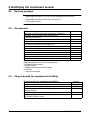
Type designation .................................................................................................... 9
2.2
Delivery package .................................................................................................. 10
2.3
Accessories .......................................................................................................... 10
2.4
Plug-in boards for expansion/retrofitting .......................................................... 10
3
Installation
3.1
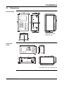
Dimensions ........................................................................................................... 11
3.2
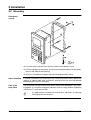
Mounting ............................................................................................................... 12
4
Electrical Connection
4.1
Installation notes .................................................................................................. 13
4.2
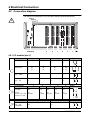
Connection diagram ............................................................................................ 14
4.2.1
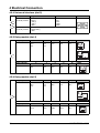
4.2.2
4.2.3
4.2.4
4.2.5
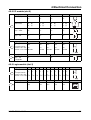
4.2.6
4.2.7
4.2.8
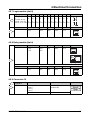
4.2.9
4.2.10
4.2.11
4.2.12
4.3
I/O module (slot 1) ...............................................................................................
I/O module (slot 2) ...............................................................................................
Logic module (slot 3) ...........................................................................................
Universal interface (slot 3) ...................................................................................
Relay module (slot 4) ...........................................................................................
Relay module (slot 5) ...........................................................................................
Logic module (slot 6) ...........................................................................................
Relay module (slot 6) ...........................................................................................
Connector 13 .......................................................................................................
Connector 14 .......................................................................................................
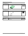
Connector 15 .......................................................................................................
Connector 16 .......................................................................................................
9
11
13
14
15
15
16
16
16
17
17
17
18
18
18
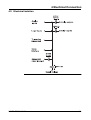
Electrical isolation ................................................................................................ 19
IMAGO F3000 / 10.01