1
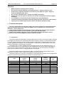
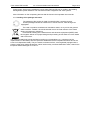
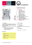
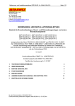
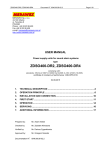
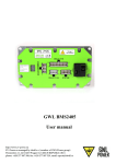
User manual ZSP135-DR No. of documentation 0404.00.95-02.2 Page 1/12 MERAWEX Sp. z o.o 44-122 Gliwice ul. Toruńska 8, Poland tel. +48 32 23 99 400 fax +4832 23 99 409 e-mail: [email protected] http://www.merawex.com.pl USER MANUAL Power supply for fire detection and fire alarm systems, smoke and heat control systems, and other fire protection systems ZSP135-DR-2A-1, ZSP135-DR-3A-1, ZSP135-DR-3A-2, ZSP135-DR-5A-1, ZSP135-DR-5A-2, ZSP135-DR-5A-3, ZSP135-DR-7A-1, ZSP135-DR-7A-2, ZSP135-DR-7A-3 conforming to the standard EN 54-4:1997/A2:2006 and EN 12101-10:2005, guidelines of VdS 2541:1996-12, 2882:2004-11, 2824:2004-03, 2593:2002-09 as well as to the Ordinance of the Polish Minister of Interior and Administration of 20.6.2007 (Dz.U. Nr 143, poz. 1002, amended on 27.04.2010), in a casing of ingress protection IP44 17.01.2012 Certificate of conformity CNBOP No. 1438/CPD/0163 Certificate of approval CNBOP No. 0583/2009 Certificate of approval VdS No. G 511007 1. TECHNICAL DESCRIPTION 2 2. SET-UP 4 3. SWITCHING ON FOR THE FIRST TIME 6 4. OPERATION 7 5. REPAIRS 9 6. REMARKS ON THE SELECTION OF THE TYPE OF THE POWER SUPPLY 11 7. ADDITIONAL INFORMATION 11 No. in the documentation system: 0404.00.95-02.2 No. of the Polish original: 0404.00.95-01.5, 17.01.2012 User manual ZSP135-DR No. of documentation 0404.00.95-02.2 Page 2/12 Warnings Before operation read this manual carefully Do not touch internal elements of the working device – danger of shock or burn Protect device against penetration of its interior by any object or liquid – danger of shock and damage of the device Do not cover ventilation holes – danger of damage of the device Ensure there is a free space of at least 10 cm at sides of the device to allow for proper ventilation It is forbidden to carry the device with mounted and connected batteries The device must be powered from the utility power grid with a protective earth terminal The device can interfere with sensitive radio or TV devices operating nearby 1. Technical description This user manual refers to the power supply with remote indication of faults defined as the mains fault and the battery fault. These two signals can be combined into a collective fault indication – see the section 2.3. In this respect it differs from the previous version, offering the collective fault indication (including the mains fault too) and a separate signal about the mains fault. Types of the available indications can be recognized by reading descriptions next to connectors or on the wiring diagram (a sticker inside the casing). 1.1. Application The power supplies are dedicated to uninterruptible supply of power in the range of 55W to 190W at the voltage 24V to devices of fire detection and fire alarm systems, systems of smoke and heat control as well as other fire protection devices, where compliance with EN 54-4:1997/A2:2006 or EN 1210110:2005, guidelines of VdS 2541:1996-12, 2882:2004-11, 2824:2004-03, 2593:2002-09 or the Polish Ordinance (specified on the title page) is required. The battery back up power supplies ZSP135-DR supply power from the utility power grid or – in case of a power failure – from internal bank of VRLA batteries (known also as AGM or gel batteries). They have two outputs, protected by fuses. During a transition from the mains power to the battery power and vice versa there are no voltage dropouts on the outputs. The power supplies fulfill the requirement of EN 54-4 to offer a collective fault indication by an appropriate connection of relay outputs of the signals (see the section 2.3). The power supplies can manage an external binary fault signal and optionally can be equipped with the device to detect unauthorized opening of the door (see the section 4.3) Type ZSP135-DR-2A-1 ZSP135-DR-3A-1 ZSP135-DR-3A-2 ZSP135-DR-5A-1 ZSP135-DR-5A-2 ZSP135-DR-5A-3 ZSP135-DR-7A-1 ZSP135-DR-7A-2 ZSP135-DR-7A-3 Nominal output current Imax a 1.0A 2.0A 1.5A 4.0A 3.5A 3.0A 6.0A 5.5A 5.0A Maximal output current Imax b 2A 3A 3A 5A 5A 5A 7A 7A 7A Battery capacity 18Ah 18Ah 28Ah 18Ah 28Ah 40Ah 18Ah 28Ah 40Ah Type of the box A A B A B C A B C User manual ZSP135-DR No. of documentation 0404.00.95-02.2 Page 3/12 Depending on the battery bank capacity the power supplies are assembled into three types of wall boxes. Dimensions Typ of the box A 390 x 350 x 90 B 390 x 350 x 140 C 450 x 350 x 180 1.2. Technical data General electrical and environmental parameters Nominal input voltage Nominal output voltage *1) Output voltage range *2) Current consumption from the battery for own needs Maximal resistance of the battery circuit *3) Number of cooperating batteries Number of outputs protected by separate fuses Working temperature *4) Ingress protection EN 60529:1991/A1:2000 Functional class EN 12101-10:2005 Environment class EN 12101-10:2005 Environmental class VdS 2593 Electric safety class EN 60950-1:2006/A11:2009/A1:2010 230V +10% -15% 27.1V 19.7…28.0V max 35 mA 250mΩ 2 2 -25…+55°C; 75°C over 2h IP 44 A 1 III I *1) In floating mode at 25°C. *2) The shown range is spanned between the voltage of a discharged battery bank (at the end of battery mode operation) and fast charging voltage. *3) The guaranteed value of the resistance of the battery circuit to trigger a fault indication. *4) VdS tested temperature-dependent charging behavior in the range -5°C to +75°C. However, at high ambient temperatures an extremely short battery life time can be assumed. Therefore, ambient temperatures higher than 40°C should not prevail at the installation location. Mechanical parameters Battery bank capacity Dimensions (W x H x D) Mounting dimensions of the box interior (W x H) dimensions with brackets (W x H) Weight without battery bank Weight with battery bank A 17Ah 390 x 350 x 90 350 x 310 350 x 370 6.4kg 18.0kg Type of the box B 28Ah C 40Ah 390 x 350 x 140 450 x 350 x 180 350 x 310 350 x 370 8.3kg 28.3kg 410 x 310 410 x 370 11.0kg 42.3kg *1) The battery of capacity 18Ah could be substituted by a battery of 17Ah. User manual ZSP135-DR No. of documentation 0404.00.95-02.2 ZSP135-DR Page 4/12 8 310 350 370 MERAWEX © © 390 90 350 Exemplary outer layout of the power supply (ZSP135-DR-5A-1) and location of the mounting holes. The detailed technical description of the power supply ZSP135-DR could be found in the technical documentation, no. of the document 0404.00.91-01.4 section 2. 2. Set-up During set-up apply directions of this manual Mount devices in a place without direct insolation Mounting and connecting could be carried out only without batteries Observe proper polarity when connecting batteries The device must be powered from the utility power grid with a protective earth terminal Check the quality of all done connections before switching the device on 2.1. Mounting The power supply should be mounted in a carefully selected place, to minimize the risk of mechanical damages and not to exceed allowable ambient temperature and humidity. Power supplies of fire protection equipment should be mounted nearby this equipment to minimize voltage drop. If possible, the power supplies should be mounted in rooms separated as fire resistant areas (e.g. switchboard rooms, technical rooms, cable chutes) The box should be mounted on the wall, using four holes in the rear side of the box. Before mounting, one has to open the box, unscrew three nuts fixing the chassis of the power supply to the rear face of the box and remove the power supply. The empty box has to be fixed to the wall by 4 steel sleeves and screws. Wall plugs made of PVC can not be applied. If there is a need to lead wires between the box and wall one has to fix enclosed brackets to the box before mounting on the wall. Having the box fixed to the wall one has to mount the power supply back. . Location of the mounting holes is show in the section 1.2. Technical data. 2.2. Connections One has to remember to connect the device to the permanent wiring using protective earth wire. It is recommended to outfit the installation with a surge protection system. The input voltage should not be cut off by the master fire protection switch. The power supplies have no own mains power circuit breakers, so a dedicated, overcurrent and short circuit resistant breaker of at least 3A current is required in the powering installation (outside the power supply). The switchboard panel and breaker of the fire protection power supply should be clearly marked (by red color and number of the power supply or by a proper description). One breaker should protect one power supply. Using this breaker for other loads is impermissible. User manual ZSP135-DR No. of documentation 0404.00.95-02.2 Page 5/12 The installation cables can enter the box from the top through three cable transits PG-11 and one PG-9 (dedicated for remote indication cables). All connections should be carried out according to the diagram inside the box (on the door). Holes of unused transits should be plugged by the plugs enclosed to the device. 10 9 8 11 BAT PRACA ZASILANIE B304 WYJ 1 WYJ 2 B301 B303 B305 12 B302 BATERIA 3 ALARM ZB ZANIK ZAS N SIEC ~230V L 4 5 2 AL ZEW 6 7 1 13 View of the power supply ZSP135-DR. Inside the box, in its upper part there is a chassis with all elements and modules of the power supply. Two maintenance-free batteries should be placed on the bottom of the box. Their capacity depends on the type of the power supply. Two LEDs for visual indication are located in the upper part of the door. No. 1 2 3,4 5 6 7 8 9 10 11 12 13 Description of elements of the power supply ZSP135-DR Recommended type and crossDescription Label section of the wire 230V 50Hz mains power 3-core multi stand cable *2) L, N and ground terminal 0.75…1.5mm2 Battery bank terminal BATERIA (BATTERY) *1) twin core multi strand flame WYJ 1, WYJ 2 retardant halogen free *2) Output terminals (OUT 1, OUT 2) 1 or 2.5mm2 Battery fault output USZ BATERII (BAT FLT) twin solid core telecom flame Output of mains fault signal USZ SIECI (MAINS FLT) retardant *2) 1x2x0.8mm2 Input of external fault signal USZ ZEW (EXT FLT) Visual indication LED – green ZASILANIE (MAINS) Visual indication LED – yellow PRACA (OPERATION) Visual indication LED – red BAT (BATTERY) Visual indication LED – green POWER Visual indication LED – yellow FAULT Temperature probe *1) The connection has to be done with wires delivered by the manufacturer. Pay due attention to the right polarity – look carefully at symbols next to the terminal. *2) Selection of wires in power and control systems of fire protection equipment can be subject of local law and regulations, e.g. civil engineering code and derived ordinances. User manual ZSP135-DR No. of documentation 0404.00.95-02.2 Page 6/12 Batteries are delivered in separate transport packages. They should be connected with wires delivered by the manufacturer. Before the connection the batteries have to be put on the bottom of the box. First, connect the batteries to the main circuit pack of the power supply, and then connect each with other. One has to pay due attention to the right polarity of the connection. In case of erroneous connection of the battery circuit a fuse shall blow. 2.3. Implementation of the collective fault indication Relay outputs of faults USZ SIECI (MAINS FLT) and USZ BATERII (BATTERY FLT) can be used to implement the output of the collective fault indication. This will indicate on a single line occurrence of any event covered by both signals. Either NO or NC contacts of the relays can be used. Both options are shown on the picture below. USZ BATERII USZ SIECI USZ BATERII USZ SIECI The visible pictograms representing the contacts of the relays refer to the state when the relays are not activated (voltage free state). By the fail safe rule this is the state indicating a fault. 3. Switching on for the first time If all connections have been carried out correctly, then after having the power supply connected to the mains the indication LEDs ZASILANIE (MAINS), PRACA (OPERATION) (diodes 8 and 9 inside the box on the circuit pack – see the picture and table in the section 2.2) and POWER (the diode no. 11) should light up. Additionally, one should hear the sound of the relay attaching the battery bank to the system. The attaching of the battery happens only when the battery bank voltage is greater than 20.5V. During the switching on one should perform two checks. 3.1. Checking ability to back up output voltage. Use a breaker in the electrical installation before the power supply ZSP135-DR to cut off the mains power. The power supply should switch to the battery mode, keeping voltage on its both outputs. Check it by whatever probe, e.g. a voltmeter or electric bulb. This state is indicated by the blinking LED POWER in the door of the power supply. The relay USZ SIECI (MAINS FLT) shall switch to the inactive state (contacts connected as on the pictogram next to the terminal). The relay USZ BATERII (BATTERY FLT) shall remain activated. The state of a relay could be checked, e.g. by an ohmmeter connected to appropriate contacts of the relay. 3.2. Checking the battery circuit When the power supply operates at presence of the mains power, break the battery circuit by disconnecting one of its wires. This state shall be detected during the first next test. It could last up to 10 minutes. Similarly, having the circuit connected again, the triggered fault indication shall be cleared automatically, but no sooner as after the first successful test – which may require another 10 minutes waiting. This state should also trigger the indication FAULT in the door of the box and the indication BAT (the red LED) on the circuit pack of the power supply. The relay USZ BATERII (BATTERY FLT) shall switch to the inactive state (contacts connected as on the pictogram next to the terminal). The relay USZ SIECI (MAINS FLT) shall remain activated. The state of a relay could be checked, e.g. by an ohmmeter connected to appropriate contacts of the relay. User manual ZSP135-DR No. of documentation 0404.00.95-02.2 Page 7/12 4. Operation 4.1. Introduction Output voltages and state indication thresholds are factory preset. After having set up the power supplies require ongoing monitoring by the staff to react to fault indication which may occur during the operation. 4.2. Input of an external fault signal The power supply can manage one binary external fault signal. To trigger this fault indication one has to shorten input contacts of the signal. The contact denoted by the sign “-“ is connected to the chassis (negative pole). The occurrence of the external fault is indicated by the blinking LED FAULT in the door of the box and by the non-activated relay. If any internal fault occurs at the same time, then the LED is on continuously. This event was assigned to the relay USZ BATERII (BATTERY FLT). 4.3. Device to indicate the opening of the door (option) The power supplies ZSP135-DR optionally could be outfitted with the protection against unauthorized access to the box interior. Opening the door (after having it unlocked) causes disconnecting of the contacts of the sensor and triggers a fault indication – the blinking LED FAULT in the door of the box and the non-activated relay. The indication doesn’t stop when the door is closed. This event was assigned to the relay USZ BATERII (BATTERY FLT). To clear the indication one has to press the contact of the sensor four times within the period not longer than three seconds. The LED FAULT returns then to the state before the door opening. The indication function is reactivated automatically after the door closing. 4.4. Indication of the state of operation The power supplies ZSP135-DR have visual and remote indications of states. The indication continues until the cause of the trigger ceases. The visual indication consists of two LEDs located in the door of the box; the green LED is labeled POWER and the yellow LED is labeled FAULT. The remote indication consists of two sockets labeled USZ SIECI (MAINS FLT) and USZ BATERII (BATTERY FLT). All of them offer three dry contacts, totally isolated from other circuits. Indication of the state of operation - continuous light - no light - blinking State of the device Visual indication POWER FAULT green yellow Relay indication USZ USZ SIECI BATERII (MAINS (BATTERY FLT) FLT) Disconnected from the mains and batteries Mains operations Battery mode A fault when mains power is present or A fault during power failure or Attention. The symbol of the relay shown in the tables above and below corresponds to the pictogram printed on the PCB next to the contacts of the relay. The shown state of the contacts denotes an inactivated relay (voltage free state). User manual ZSP135-DR No. of documentation 0404.00.95-02.2 Page 8/12 Indication of faults yellow LED FAULT relay USZ BATERII (BATTERY FLT) Fault Mains power failure – including a failure of the converter Battery bank not present or voltage of the connected bank below 10V Low voltage (<24V) during battery test *1) High resistance (>250mΩ)of the battery circuit *1) Blown battery fuse Battery discharged (<21.6V) during battery mode Blown output fuse Open door *2) External fault Too low voltage (<20.5V) of the connected battery bank *3) *1) This fault indication is cleared automatically after the first successful test of the battery circuit continuity and resistance measure. *2) LED FAULT blinks cyclically. *3) LED FAULT blinks with short flashes. Additionally, inside the box on the circuit pack there are two LEDs – the green ZASILANIE (MAINS) and the yellow one PRACA (OPERATION) – to differentiate between power failure and a damage of the device, as well as a red one BAT – to indicate the state of the battery bank. Indication of the state of mains power (LEDs on the circuit pack) green LED yellow LED ZASILANIE (MAINS) PRACA (OPERATION) State of mains power Correct mains operation Damaged converter Mains power failure Indication of the state of the battery bank (the LED on the circuit pack) red LED BAT State of the battery bank Battery OK Battery test failure High resistance of the battery circuit User manual ZSP135-DR No. of documentation 0404.00.95-02.2 Page 9/12 4.5. Maintenance The device doesn’t require any special maintenance activities. During the normal operation one has to take care only to keep the necessary cleanness in the proximity of the box. It must be taken into consideration that if battery expected life is e.g. 12 years at temperature of 20°C, then it is 10 years at temperature of 25°C and drops twofold when temperature increases further by 8°C. Attention: CNBOP (a Polish notified body) and VdS recommend replacing batteries after 4 year of operation irrespectively of their state. 4.6. Inspections Frequency of inspections is regulated by provisions appropriate for the powered device, but shall not be lesser than once a year. During an inspection two functional tests described in section 3. Switching on for the first time should be carried out. Additionally, it should be checked if a fault indication triggered by the power supply is transmitted to the fire alarm control panel. 5. Repairs 5.1. Fuses A user can replace only the fuses shown below. Battery circuit (quick-break F) Output circuit (quick-break F) Mains input circuit (slow-blow T) ZSP135-DR-5A ZSP135-DR-7A 5A 5A 3.15AT 10A 10A 3.15AT B301 B303 B304 B305 B201 (3) (4) (5) (1) (2) ZSP135-DR-2A ZSP135-DR-3A B302 BATERIA WYJ 1 3 WYJ 2 ALARM ZB ZANIK ZAS AL ZEW N L 5 4 1 2 Placement of fuses in the power supply ZSP135-DR Additionally, there is a fuse B201 on the circuit pack of the power supply. Its damage indicates a serious failure of the device. The user must not replace it. Guarantee and post-guarantee repairs are conducted by the staff of either the manufacturer or its authorized partner. User manual ZSP135-DR No. of documentation 0404.00.95-02.2 Page 10/12 5.2. Diagnostics and correcting of malfunctions Each case of triggering the visual indication FAULT – except mains power failure and the failure of the converter – is accompanied by the change of state of the relay USZ BATERII (BATTERY FLT). Each case of mains power failure (including a damage of the converter of the power supply) triggers fault indication on the relay USZ SIECI (MAINS FLT). To diagnose and correct a malfunction one can use the table below, paying attention to the visual indication of the state of the power supply. No voltage on one of outputs No backup voltage on both outputs in case of a mains power failure (the second indication when there is mains power) The device indicates a fault when the mains power is present and output voltages are correct The device indicates the battery mode when the utility power is present The device indicates a fault by the relay USZ BATERII (BATTERY FLT) during the battery mode The device indicates a fault by the blinking diode PRACA (OPERATION) FAULT POWER Symptoms ZASILANIE (MAINS) Visual indication LEDs in a damaged power supply Circuit Door pack Check − output fuses (4,5) − electrical contacts on the right output terminal − battery fuse (3) − connections of the batteries − state of the batteries *1) − quality of the connections of the batteries *2) − state of the batteries *2) − mains power fuses (1,2) − state of the mains power − a serious malfunction – call the service − the battery bank is nearly discharged (battery voltage below 21.6V). If the power failure continues the battery bank will be disconnected − external fault − an unauthorized person has opened the door (optional indication) *1) If the battery voltage is < 20.5V the battery bank shall not be connected to the system. Batteries should be charged by an external charger or replaced. *2) The indication could have been triggered during the battery test – then red LED BAT on the circuit pack blinks, or because of high resistance of the battery circuit – the red LED BAT is on continuously (see the section 4.4). Having the batteries replaced or the connections corrected, the indication shall be cleared no sooner then after a correct run of the nearest test. It may last up to 10 minutes. User manual ZSP135-DR No. of documentation 0404.00.95-02.2 Page 11/12 6. Remarks on the selection of the type of the power supply Power supplies ZSP135-DR have various output currents and cooperate with internal batteries of various capacities. The selection of the specific type should depend on requirements of the specific load (powered devices). First, one has to calculate the required battery capacity. To do this one has to take into account consumption of current during various states of operation of the powered devices as well as additional consumption for own needs during the mains power failure. The minimal capacity of the battery bank can be defined with the help of the following formula: QBAT = 1.25 × [(ISB + IQ) × TSB + (IAL + IQ ) × TAL + IACT × T3] where: QBAT 1.25 ISB IQ TSB IAL TAL IACT T3 - battery capacity [Ah] - safety coefficient to account for capacity loss after seasoning and wear-out - current employed by loads during the standby [A] - quiescent current [A] - required standby time [h] (4h, 30h or 72h) - current employed by loads during alarm [A] - alarm duration [h] (0.5h) - current employed by actuators during an alarm [A] - duration of three full work cycles of the actuator [h] Attention: the power supply requires some minimal battery capacity during the standby and alarm for its own needs (IQ = 0.035A). This is 3.3Ah for the standby of 72h, 1.4Ah for 30h, and 0.20Ah for 4h. Having calculated from the above formula the required capacity of the battery bank, one can use the table in the section 1.1 to select the power supply, observing the constraint of the maximal capacity to mount in the given power supply and choosing the standard value which must be greater than the calculated minimal capacity. Additionally, the following conditions must be met: ISB < Imax.a , IAL < Imax.b and IACT < Imax.b. 7. Additional information 7.1. Manufacturer’s remarks The manufacturer reserves the right to introduce changes in the design and technology which shall not impair quality of the product. 7.2. Cooperating devices 7.2.1. Tester A tester of power supplies ZSP135 has been developed for the service and maintenance staff. It allows reading values and states recognized by the controller of the power supply without intrusion into circuits of the power supply and without measurement equipment. It is also possible to determine the state of the battery bank during the test and to force a test outside the automatic schedule. 7.2.2. Communication module The communication module ZSP135-MK is another optional outfit. It enables transition of data from the power supply via the RS232 or RS485 interface. The read data include measured values and states recognized by the controller of the power supply. The module was designed to be mounted inside the box of the User manual ZSP135-DR No. of documentation 0404.00.95-02.2 Page 12/12 power supply. Owing to the module the power supply ZSP135-DR can be visible in the Building Management System GEMOS. The manufacturer offers integration with other systems. More information on the cooperating devices shall be found in their separate user manuals. 7.3. Handling of the package and waste The package of the product is made of materials which could be recycled. Unused packages should be handed over to a dust collector, after having them segregated. The used out product constitutes non-hazardous waste, not to put into the general waste container. Instead, it should be handed over to the local collector of the waste electric and electronic equipment. Professional handling of the waste electric and electronic equipment (WEEE) shall limit negative effects of improper storage and processing of this waste on human health and environment. The used out batteries should be handled according to local regulations, e.g. introduced as the implementation of the Battery Directive (Directive 2006/66/EC of the European Parliament and of the Council of 6 September 2006). They are sealed, maintenance-free, valve-regulated (equipped with a pressure relief valve) lead acid batteries. When used out they constitute hazardous waste, coded in the European Waste Catalogue as 16 06 01*.