1
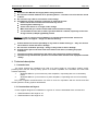
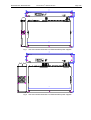
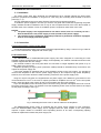
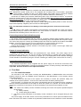
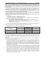
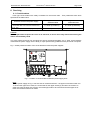
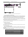
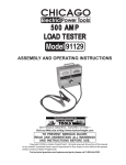
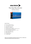
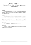
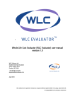
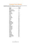
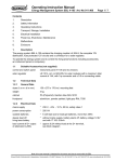
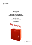
ZDSO400-DR2, ZDSO400-DR4 o Document N . 0546.00.95-02.2 Page:1/18 MERAWEX MERAWEX Sp. z o.o. 44-122 Gliwice ul. Toruńska 8 POLAND Phone: +48 32 23 99 400 Fax +48 32 23 99 409 e-mail: [email protected] http://www.merawex.com.pl USER MANUAL Power supply units for sound alarm systems type ZDSO400-DR2, ZDSO400-DR4 complying with: standards: EN-54-4:1997+A1:2002+A2:2:2006 & EN-121001-10:2005, certificate of constancy of performance 1438-CPR-0319 04.08-2015 1. TECHNICAL DESCRIPTION .............................................................................. 2 2. OPERATION PRINCIPLE ................................................................................... 6 3. INSTALLATION AND CONNECTION............................................................... 10 4. FIRST START ................................................................................................... 11 5. OPERATION ..................................................................................................... 14 6. SERVICING ....................................................................................................... 16 7. ADDITIONAL INFORMATION .......................................................................... 17 Prepared by: Mr. Adam Kretek Checked by: Mr. Zdzisław Klimasara Verified by: Mr. Dariusz Cygankiewicz Approved by: Mr. Grzegorz Szandar o Documentation N : 0546.00.95-02.2 ZDSO400-DR2, ZDSO400-DR4 o Document N . 0546.00.95-02.2 Page:2/18 Warnings Read this User Manual thoroughly before using the device. Do not touch internal elements of an operating device – to avoid a risk of an electric shock or burns. Do not touch any cable or connectors under voltage Pay attention to basic manners if working on electrical devices: Switch off the device and disconnect from any source Protect against switching on Check if the device is no longer under voltage Make sure that you cannot contact other electrical device nearby You should also have this in mind if you work with DC <120Volt, especially in the case of high current (>1Amper @ 24Volt) present Attention: in case of a short circuit of battery it is possible that current from several one hundreds Ampere can appear – danger for massive burning. Protect the device from the possibility of any items or fluids entering in – they can cause a risk of electric shock and device damage. Do not cover ventilation openings – doing so may result in device damage. Provide a free space of at least 8 cm at the sides of the device, enabling its proper ventilation. The device must be supplied from the mains with a protective earthing terminal. The device may interfere with operation of sensible radio and television equipment located nearby. 1. Technical description 1.1. Intended use The power supplies are intended to be used as a power supply for voice alarm systems (VAS), providing them with the backup battery power for acoustic amplifiers and controllers and other VAS modules separately: 1. ZDSO400-DR2 for up to maximum 6 power amplifiers, cooperating with one or two battery banks. 2. ZDSO400-DR4 for up to maximum 12 power amplifiers, cooperating with one to four battery banks. The power supplies mentioned above can also be used for cooperation with the smoke and heat control systems including systems located afar. 1.2. Construction and layout Power supplies designed for installation in a typical 19” rack are assembled within a metal case: 1. ZDSO400-DR2 of the height of 1U, 2. ZDSO400-DR4 of the height of 2U. o ZDSO400-DR2, ZDSO400-DR4 Document N . 0546.00.95-02.2 Page:3/18 483 SIEĆ BATERIA ŁADOWANIE USZKODZENIE A 328 B 42.5 31.8 ZDSO400-DR2 45 465 445 Fig.1. View and nominal dimensions of ZDSO400-DR2 power supplies. 483 465 87 A SIEĆ BAT ERIA ŁADOWANIE USZKODZENIE 328 B 445 Fig.2. View and nominal dimensions of ZDSO400-DR4 power supplies. 89 44.5 ZD SO 400-DR4 ZDSO400-DR2, ZDSO400-DR4 o Document N . 0546.00.95-02.2 Page:4/18 ZDSO400-DR2 power supply Note: The power supply unit is supplied together with: 1. 2. 3. 4. 5. 6. A temperature sensor; Set of plugs for connecting power supply of VAS amplifiers (6 pcs. of the PC 5/2-ST-1-7 plugs); Set of plugs for connecting power supply of VAS controllers (2 pcs. of the MSTB2,5/2-ST plugs); Set of plugs for connecting external signalling inputs (2 pcs. of the MSTB2,5/2-ST plugs). Set of plugs for connecting remote signalling outputs (3 pcs. of the MSTB2,5/3-ST plugs). Ferrite core, toroidal, insulted, dimensions: 22x13.7x6.3 F830 (6 pcs.). Fig.3. View of the front and back panel of the ZDSO400-DR2 power supply unit. A digital display panel, a USB port and 4 LED indication diodes are installed in the front panel of the power supply unit: 1. 2. MAINS (green) BATTERY (yellow) 3. 4. CHARGING (green) FAULT (yellow) The back panel contains: 1. 2. 3. 4. 5. 6. 7. 8. A male IEC socket for connecting the mains cable (230Vac 50-60Hz). Four screw connectors for connecting two 24 V battery banks (BAT1, BAT2) and two neighbouring connectors of the circuit equalizing voltages of the battery banks M. A socket for connecting the temperature sensor (TEMP SENSOR). Two input sockets for external fault indication (EXT. FAULT 1 and EXT. FAULT 2). Three output sockets of relay indication system (MAINS FAULT, BATTERY FAULT and GENERAL FAULT). 6 sockets for connecting VAS 24V amplifiers (from OUT1 to OUT6). They can also be used for connecting the smoke and heat control system devices. A double socket for connecting the network controller and other VAS modules designed to work with 24V power supply (ADDITIONAL OUTPUT 24V). They can also be used for connecting the smoke and heat control system devices. Ethernet connector (option). ZDSO400-DR4 power supply Note: The power supply unit is supplied together with: 1. 2. 3. 4. 5. 6. A temperature sensor; Set of plugs for connecting power supply of VAS amplifiers (12 pcs. of the PC 5/2-ST-1-7 plugs); Set of plugs for connecting power supply of VAS controllers (4 pcs. of the MSTB2,5/2-ST plugs); Set of plugs for connecting external signalling inputs (2 pcs. of the MSTB2,5/2-ST plugs). Set of plugs for connecting remote signalling outputs (3 pcs. of the MSTB2,5/3-ST plugs). Ferrite core, toroidal, insulted, dimensions: 22x13.7x6.3 F830 (12 pcs.). ZDSO400-DR2, ZDSO400-DR4 o Document N . 0546.00.95-02.2 Page:5/18 Fig. 4. View of the front and back panel of the ZDSO400-DR4 power supply unit A digital display panel, a USB port and 4 LED indication diodes are installed in the front panel of the power supply unit: 1. 2. MAINS (green) BATTERY (yellow) 3. 4. CHARGING (green) FAULT (yellow) The back panel contains: 1. A PC-type socket for connecting the mains cable (230Vac 50-60Hz). 2. Eight screw connectors for connecting four 24 V battery banks (BAT1, BAT2, BAT3, BAT4) and four neighbouring connectors of a circuit equalizing voltages of battery banks M. 3. A socket for connecting the temperature sensor (TEMP SENSOR). 4. Two input sockets for external fault indication (EXT. FAULT 1 and EXT. FAULT 2), 5. Three output sockets of relay indication system (MAINS FAULT, BAT FAULT and GEN FAULT). 6. 12 sockets for connecting VAS 24V amplifiers (from OUT1 to OUT12). They can also be used for connecting the smoke and heat system devices. 7. Two double sockets for connecting the network controller and other VAS modules designed to work with 24V power supply (ADDITIONAL OUTPUT 24V). They can also be used for connecting the smoke and heat system devices. 8. Ethernet connector (option). 1.3. Basic electrical parameters Nominal mains voltage Power factor Efficiency (while charging the battery) Output voltage stabilisation Leakage current in the protective cable Maximum power consumption from the mains Nominal voltage of the external battery bank Nominal voltage of the floating mode operation at 25°C Nominal voltage of the bulk charging mode operation at 25°C Temperature compensation factor of the floating mode operation and bulk charging Maximum capacity of supplied battery banks Maximum number of battery strings Maximum charging current *1) Maximum resistance of battery circuit Load capacity of power supply outputs provided for VAS amplifiers Load capacity of power supply output provided for network ZDSO400-DR2 ZDSO400-DR4 230V +10% -15% 50-60Hz 0.98 84% 0.5% <1.5mA <3mA 2.7A 5.4A 24V 24V 27.1V 27.1V 28.3V 28.3V - 48mV/ºC - 48mV/ºC 320Ah 640Ah 2 16A 50mΩ 6 x 30A 1x6A 4 32A 50mΩ 12 x 30A 2x6A *2) *4) *5) *2) *4) *5) ZDSO400-DR2, ZDSO400-DR4 o Document N . 0546.00.95-02.2 controller and other VAS modules The quiescent current consumption from the battery Current consumption from the batteries after LVD disconnection *3) Range of output voltage Nominal output current which can be supplied continuously to the additional outputs of 24V Imax.a [A] Maximum current which the power supply unit can take from a single battery when the main power supply is cut off or disconnected [A] Maximum current consumed from all battery strings in the case of the fire alarm [A] Page:6/18 < 300mA < 3mA 20.0…28.8V 2A < 600mA < 6mA 20.0…28.8V *2) 4A *2) 96A 96A 186A 372A *1) Guaranteed value of battery bank circuit resistance, at which the fault indication system is switched on for each battery string separately. *2) The given capacities of the batteries include current consumption Imax.a from the additional 24V outputs for the VAS controller: 2A for ZDSO400-DR2, 4A for ZDSO400-DR4; When in need of consumption of higher current than the given ones, the battery capacity must be decreased by 25Ah for every 1A current over the given Imax.a values. Maximal current Imax a for ZDSO400-DR2 is 6A, for PSU-24V-4 is 2x6A (two separated outputs 6A) – the value corresponds to the 6.3Amps fuses used. *3) The listed range includes voltage values between the voltage of a discharged battery bank (at the end of the floating mode cycle) and the value of the bulk charging mode voltage, including temperature compensation. *4) The following User Manual does not include the description of the battery selection and calculating its capacity. *5) In one 24V battery string (separately each in system) the battery of the same capacity and type must be used. When you need to replace a battery, please, replace their whole set. st You can use in the system various battery capacities in various strings (e.g. two pcs. 105Ah as 1 string nd 24V and two pcs. 150Ah as 2 24V string) but the battery must have the same voltage parameters (in charging mode, floating mode, temperature compensation, discharging/disconnect mode). Consequently, the batteries in one string should be from the same producer and of the same type and capacity. 1.4. Recommended working conditions Relative humidity Direct sunlight exposure Surges during operation Ambient temperature Limits of acceptable storage temperature Working temperature – class 3K5 according to EN 60721-3-3 max. 80% inadmissible inadmissible -40…+85°C -5…+45°C 2. Operation principle The microprocessor controller checks the presence of the mains power, battery state, state of external alarms inputs and a number of internal parameters (e.g. acceptable time of the bulk charging). If an improper operation of the device is detected, a fault indication is generated. This operational state is signalled by corresponding diodes, lighting up in the front panel, and by three remote indication relays accessible in the back panel. The relays are activated, when no fault indications are being generated; it means that a fault indication causes deactivation of the relay. The power supply circuit is based on a direct floating mode system. The power supply, supplied from the mains, is connected in parallel with an external battery bank. The VAS amplifiers supplied with their own power supplies are required not to consume power from the 24V voltage. However, when power failure, they should automatically switch over to use the battery power supply. Figs. 5a. and 5b. below present flowcharts of both power supplies. o ZDSO400-DR2, ZDSO400-DR4 Document N . 0546.00.95-02.2 Page:7/18 DIGITAL MEASUREMENT PANEL LED SIGNALLING PANEL USB SOCKET U IA IB T FAN Mains Battery Charging Fault FAN BATTERY CURRENT MEASUREMENT SYSTEM RECTIFIER 400W MICROPROCESSOR CONTROLLER BATTERY VOLTAGE EQUALISATION SYSTEM RB RGR 1 2 3 4 5 6 ETHERNET Aux 2 Temp sensor Mains fault Bat fault Gen fault REMOTE SYGNALLING OUTPUTS Ext flt 2 1 Ext flt 1 POWER SUPPLY OUTPUTS FOR DSO MODULES BAT 24V M BAT 24V M BATTERY CONNECTORS BATTERY CONNECTORS DSO CONTROLLER POWER SUPPLY Bm Ba 12V BATTERY 12V BATTERY Fig.5a Block diagram of ZDSO400-DR2 power supply. EXTERNAL SYGNALLING INPUT 230V 50-60Hz 230V 50Hz o ZDSO400-DR2, ZDSO400-DR4 Document N . 0546.00.95-02.2 Page:8/18 BATTERY CURRENT MEASUREMENT SYSTEM RECTIFIER 400W BATTERY VOLTAGE EQUALISATION SYSTEM RB RGR 7 9 10 11 12 Bat 24V 4 BAT 24V M Bat 24V 3 M 8 3 4 Aux Bm Ba 12V BATTERY 12V BATTERY DIGITAL MEASUREMENT PANEL U IA IB T ZDSO400-DR4 FAN LED SIGNALLING PANEL USB SOCKET Mains Battery Charging Fault FAN BATTERY CURRENT MEASUREMENT SYSTEM RECTIFIER 400W MICROPROCESSOR CONTROLLER BATTERY VOLTAGE EQUALISATION SYSTEM RB RGR 1 2 3 4 5 6 ETHERNET 2 Aux Temp Mains fault sensor Bat fault Gen fault REMOTE SYGNALLING OUTPUTS Ext flt 2 1 Ext flt 1 POWER SUPPLY OUTPUTS FOR DSO MODULES BAT 24V Bat 24V 2 M Bat 24V 1 M 230V 230V 50-60Hz 50Hz BATTERY CONNECTORS BATTERY CONNECTORS DSO CONTROLLER POWER SUPPLY EXTERNAL SYGNALLING INPUT Bm Ba 12V BATTERY 12V BATTERY Fig.5b Block diagram of ZDSO400-DR4 power supply. When the mains present, the power supply maintains the external battery banks in their fully charged state. Power supply’s operation is controlled by the microprocessor controller, which independently supervises the batteries, maintaining the floating mode voltage in them (depending on ambient temperature, if the external temperature sensor has been connected). This sensor should be located near the battery. If the sensor is absent, the controller maintains voltage corresponding to the ambient temperature of 25°C. In case of power failure, the loads connected to the power supply are powered directly from the battery bank – this is the battery mode. As the mains power supply returns, the battery bank charging current is above a set point, the power supply proceeds to the bulk charging mode. This mode is characterised by charging with the limited current at the increased voltage. The end of the bulk charging at a fully operational battery bank is defined by a significant drop of charging current after ZDSO400-DR2, ZDSO400-DR4 o Document N . 0546.00.95-02.2 Page:9/18 the preset charging voltage has been reached, after which the power supply decreases the voltage to the level of floating mode voltage, continuing charging with this voltage. If the battery bank is faulty, the bulk charging is interrupted in the fault mode after the maximum, preset charging time has been exceeded or when the permissible ambient temperature of the battery bank is exceeded. The circuit of the ZDSO400-DR2 or ZDSO400-DR4 power supply is equipped with a LVD – an internal switch of deep discharge implemented in the relays in their output circuits (one relay in each circuit for powering amplifiers and one at each double outputs for powering the VAS controller). They disconnect the outputs from the battery banks when the battery reaches the minimum permissible discharge level, thus preventing it from further discharging and preventing it from being destroyed. The second BD disconnector (Battery Disconnector) ensures powering continuity for additional outputs from the rectifier in the case of short circuit of the battery terminals of the charger. Measurement of battery circuit resistance is an additional function of the controller. The resistance measurement takes place only in the floating mode operation. Detection of battery circuit resistance increase caused by an increase in internal resistance of the battery or by an increase of battery connection resistance, causes the indication for reaching high battery circuit resistance to be sent. If the battery bank gets disconnected, the controller detects a significant increase of battery circuit resistance and indicates a device configuration error. The power supply is equipped with a function of voltage equalisation between batteries of each battery string. Voltage equalisation takes place as a result of loading the half of batteries which exhibit higher voltage, with a small current, of 100mA. This function is called for if the voltage difference exceeds 0.1V. The use of voltage equalising circuit requires an additional connection to be introduced between the M terminal of a given battery string and the median point of the battery itself. This system is resistant to an incorrect connection of this connector (to an inappropriate terminal of any battery), indicating a fault in such the situations. The lack of this connection is automatically detected which results in switching off the voltage equalising system. The circuit of the ZDSO400-DR2 or ZDSO400-DR4 power supply is continuously controlling the state of circuit breakers in the output circuits provided for amplifiers and of the circuit breaker (breakers) in the output circuit provided for the VAS controller. Fault to any of them results in a fault signal being generated (the signalling lights on the front panel of the power supply unit are switched on and the remote signalling to be put out), and in addition, switching on a yellow LED diode located near the faulted circuit breaker. When the power supply unit is switched on, state of load at the outputs designed for VAS amplifiers is checked. Lack of current consumption from these outputs is required. If any of the amplifiers has e.g. its own power supply switched off (or faulty), which results in an attempt of switching it on using output voltage of the power supply unit, such the state shall be detected and the relay present at this output shall not switch on, and, in addition, fault indication shall be switched on. Relays present at the other outputs shall simply switch on, supplying voltage to operational amplifiers. During the power supply start, the current consumption from the output designed for the VAS controller is only permitted. Its load present at this output, however, decreases the current provided for battery bank charging. NOTE: If the system has already been switched on and any of the amplifiers starts consuming current using output voltage as a result of fault – then leaving the power supply system in this state may eventually result in an uncontrollable discharge of the battery, despite proper functioning of the power supply system itself. ZDSO400-DR2, ZDSO400-DR4 o Document N . 0546.00.95-02.2 Page:10/18 3. Installation and connection 3.1. Installation The power supply have been designed and manufactured as a cassette offering the IP20 ingress protection, prepared for installation in a typical 19” rack using four mounting holes located in the front panel (Fig. 1, 2). The rack dedicated to the Voice Alarm Systems must have IP30 ingress protection. To install the power supplies in the rack you need to use guide rails. Guide rails supporting the power supply cassette should be installed in such a way as not to impede the flow of air to the fans located on the both sides of the cassette. The 8 cm ventilation space is required on both sides of the case. NOTES: 1. The power supply is not equipped with its own mains switch, thus it is necessary to use a S301 C10A switch in the power supply circuits (outside of the power supply). 2. The required electric installation should be provided as a permanent installation equipped with an overvoltage protection system. 3.2. Connection Connecting power supply to the mains Connecting the power supply to the mains should be implemented by using a 3-wire YLY-type cable of 2 the 1.5 mm cross-section, equipped with the IEC plug. Load connection The ZDSO400-DR2 or ZDSO400-DR4 power supply has been designed for connecting the VAS amplifier modules supplied with the 24V voltage, and separately, the network controllers and other VAS modules supplied with the 24V voltage. The sockets located in the back panel allow for connection of single amplifiers with power of up to 500W, using 2-pin connectors. Amplifiers operating at higher power (maximum 1000W) should be simultaneously connected to two outputs of the power supply unit. If the main amplifier is equipped with its spare amplifier present in the VAS system, it is possible to connect both amplifiers to the common power supply output (or two outputs for high power amplifiers). However, this connection should be made excluding connectors of the power supply units. Plugs for output connection are supplied with the power supply unit. Maximum cross-section of the 2 2 connected wires is 6 mm in the case of outputs provided for amplifiers and 2.5 mm for the 24V power supply output providing power supply for the VAS controllers and other VAS modules. If you use amplifiers, when the mains power connected, they yield the load higher than 47uF on their DC mains power input. Then, it is required to use the separating ferrite cores mounted close to the output socket plugs according to the Fig. 6. Fig. 6. Mounting the ferrite cores on the DC cables to the amplifiers The ZDSO400-DR2 power supply is equipped with two power supply outputs for VAS controllers, while the ZDSO400-DR4 power supply unit is equipped with four such outputs. If the VAS system requires a higher number of controllers and cooperating devices to be used, corresponding splitting should be implemented outside the power supply unit. ZDSO400-DR2, ZDSO400-DR4 o Document N . 0546.00.95-02.2 Page:11/18 Connecting battery bank Power supply units are designed to cooperate with VRLA-AGM battery banks. Note: Because the power supply unit is not equipped with a battery bank circuit breaker, appropriate circuit breakers, separate for each of the battery banks (24V battery string), should be installed near each positive terminal of one battery string or between batteries in each string. 2 Connection of a battery set should be made using wires of the cross-section of 25 mm for terminals located in the back panel of the power supply unit, marked as BAT taking a proper care to provide them with the proper polarity. A reverse connection of a battery bank may result in a severe fault to the power supply unit itself, as well as to the connected, external devices. Positive terminal poles, marked with numbers, enable distinguishing battery banks as each of them is supervised separately. Negative poles are short-circuited together. Note: The maximum resistance of the battery circuit cabling and fuse should not access 4mΏ. The M outputs of the voltage compensation circuit should be connected with the center of the appropriate battery string by means of the cables of the cross section of 0.75mm2. The connection must be protected near the battery with its own fuse of 0.5 ... 2AF. Connecting external fault indication system The power supply is equipped with two inputs for connecting external fault indication systems, the sockets of which are located in the back panel. Corresponding plugs are supplied with the power supply unit. One of the plugs has a factory pre-installed jumper and it has to be placed in the alarm socket EXT. FAULT 1, even if this input is not used, since it is activated when its contacts become disconnected. The second input EXT. FAULT 2 is activated by short-circuiting its terminals. External fault indication systems should be connected using the YnTKSY 1x2x0.8 type cables (the 2 cross-section of 0.8 mm ). Output of remote indication Outputs of remote relay indication are implemented as 3-pin sockets. The power supply unit is supplied with 3-pin plugs. You can use the normally connected (NC) or normally open (NO) contacts of the internal indication relays by connecting to proper pin in the appropriate socket. Remote indication 2 circuits should be connected by using the YnTKSY 1x2x0.8 type cables (of the cross-section of 0.8 mm ). Connecting temperature sensor The external temperature sensor supplied with the power supply unit should be connected to the appropriate socket (Temp sensor). The sensor should be placed in a direct proximity of the battery bank, if possible, between the walls of two adjacent batteries. 4. First Start 4.1. The initial information The first start of the VAS system including the ZDSO400-DR2 or ZDSO400-DR4 and connected batteries should be done by qualified service personnel of the Manufacturer or the properly trained authorized personnel. The tests during the first start of the system are necessary to ensure the operation safety and reliability of the system operation – both from the mains and from the battery backup power. At the first start, you should check the system completeness and all VAS modules for their compliance with the electrical specifications of the object in which the system is to operate. The check should also include the correctness of connections as well as the battery connected and the indication circuits. Note: 1. The values of the battery circuits’ resistance ensuring the correct VAS system operation depend on two factors: a) battery capacity b) current during the fire alarm 2. The factory preset parameters of the battery circuits’ resistance can be changed during the first start. The power supply, at the start, stores in its memory information on to which inputs the batteries have been connected. The check is carried out by automatic measurement of the resistance of each individual ZDSO400-DR2, ZDSO400-DR4 o Document N . 0546.00.95-02.2 Page:12/18 battery circuit. It is assumed the battery is connected if the measured resistance is lower than 2Ω. The resistance measurements of the battery circuits are conducted periodically and on such the basis the battery configuration change can be detected. The detected change is indicated by fault indication and corresponding error code. The configuration change can be accepted in the PC software or by the next start of the device. If the power supply is started without the batteries connected, it will indicate the configuration fault for each of them. In this state, the outputs of the uninterruptible power supply for the amplifiers are not connected and the only output connected is the additional output for the VAS controller. In such the case, you need to connect a battery (one or several ones) and cancel the fault indication to have the configuration accepted by the device and start the normal operation. At the start, the device restores the recently saved operation parameters. The change of these parameters is possible in the PC software through the USB or the Ethernet connection (if available) after connection to a computer network by means of any internet browser. After the successful start of the system, please, perform the following tests of the devices’ operation described below. 4.2. Maximum resistance of battery bank circuit As far as the indication of the impermissible increase of the battery bank circuits resistance is concerned, we can differentiate two types of resistance: initial resistance corresponding to the battery circuit resistance (including the battery itself) after making the connections (cables, terminals and fuses) permissible battery circuit resistance increase (e.g. due to aging process); its exceeding will trigger the fault circuit indication. The sum of the initial resistance and the permissible battery circuit resistance increase is indicated in the power supply certificate 1438-CPR-0319 and it cannot be higher than 50mΩ. The resistance values have been listed in the table below. mΩ Default value (150Ah-160Ah) mΩ Initial resistance 5 17 25 Permissible resistance increase 5 10 25 Total resistance 10 27 50 Resistance value Resistance categories Minimum value Maximum value mΩ Serially produced ZDSO400-DRx power supplies are supplied with the default set values (as above) to provide the correct operation of the battery strings resistance measurement circuits with the batteries of up to 160Ah. In the case of using lower capacity batteries (e.g.: 65Ah, 100Ah), it is possible to change the default set values into the ones mentioned below: • To provide the correct operation of the connected amplifiers, even during their battery operation with the maximum output power, the power supply should be used with appropriate battery cables. The cables will ensure the maximum voltage drops will not be exceeded even at the maximum current values consumed from the batteries. For this reason, please use the cables exclusively prepared for this application - they will ensure the 4 mOhm resistance (measured together with a fuse placed in their string) will not be exceeded. • The change of the default set values of the battery string resistance level excess indication is possible by means of the PC software (see point 5.4) for the device configuration and power supply monitoring • After running the PC software (see point 5.4), please read the measured resistance value of each battery string (in the particular case in each of the connected 24V battery strings, batteries of various capacities can be connected). Please, compare the measured values with the permissible values given below. Please, keep in mind the battery cables and fuse resistance, the internal resistance of two serially connected batteries as well as the connections’ resistance (screwing the batteries’ clamps) influence measurements’ results. ZDSO400-DR2, ZDSO400-DR4 Capacity of battery in a specific string 150-160Ah 100Ah 65Ah 40Ah • • o Document N . 0546.00.95-02.2 Maximum value of measured string resistance (acceptable) max 20 mOhm max 22 mOhm max 25 mOhm max 28 mOhm Proposed value to enter as initial resistance (you can also accept measured value) 17mOhm (default value) 20 mOhm 23 mOhm 26 mOhm Page:13/18 Proposed value to enter as permissible resistance increase 10 mOhm (default value) 15 mOhm 20 mOhm 24 mOhm If the values read are within the specified range (depending on the capacity of the connected batteries), you can change the reference resistance value into the measured one or, in the case of 150-160Ah batteries, left it unchanged. Similarly, you can change the value of the permissible increase depending on the battery capacity used. If you use various capacity batteries in different battery strings, you can only enter one value common for all the strings! If the preset settings have not been changed during mounting the power supply, the default settings are valid. 4.3. Checking the ability to maintain the output voltage Please, disconnect the mains. The power supply should start operating in the battery operation mode supplying voltage to its all outputs for powering the VAS modules. The voltage presence and its value should be checked by means of a voltmeter. In this state, the MAINS LED on the front panel of the ZDSO400-DR2 or ZDSO400-DR4 should be off and the FLT LED should be on. The both relays of MAINS FLT and GENERAL FLT should come into the idle mode (the terminals’ position should be according to the figure near the connector). The state of the relays can be checked by means of an ohmmeter connected between their appropriate terminals. During the check, the connected VAS modules should function normally. 4.4. Checking battery circuits high resistance indication When ZDSO400-DR2 or ZDSO400-DR4 is powered from the mains, you should break the circuits of each of the battery strings one after another – by means of the respective breaker. This is the simulation of an extreme growth of resistance of the battery circuit. The state should be detected during the next test. It can last from 5 do 400s, typically 70s (the default value of the measuring period). Similarly, after cancelling the break, the generated alarm will be cancelled automatically but after the next successful test – after the analogical period of time. The state should be indicated by the ZDSO400-DR2 or ZDSO400-DR4 power supply by the FLT LED on and positioning of the relays of BATTERY FLT and GENERAL FLT in the idle mode (the relay position according to the figure close to the connector). During the above test, the connected VAS modules should operate normally. 4.5. Sequence for start operation The following sequence of switching on devices in the VAS system is suggested: 1. All devices should be switched off (all AMPs and ZDSO400-DRx) 2. Connect batteries (all strings) to the unit 3. Switch on the mains (230Vac) - for all AMPs and ZDSO400-DRx 4. Wait for 60s 5. AMPs should be connected (24Vdc) to ZDSO400-DRx ZDSO400-DR2, ZDSO400-DR4 o Document N . 0546.00.95-02.2 Page:14/18 5. Operation 5.1. General information Output voltages and signalling thresholds are preset as factory default values. Power supplies after installing require supervision by the service team as some emergency states may occur during the operation of the device. 5.2. Operation safety The power supply unit is a Class I device according to the standard EN 60950-1:2007+A1:2011 (IEC950), designed for connecting to a permanent, one-phase installation using an earthing cable, according to the HD 60364-4-41:2007 Standard Electric installations at construction sites. The metal case of the power supply units is connected to a protective terminal (PE). The circuits used for connecting the battery, remote indication outputs and remote indication inputs are separated from the power supply circuits and from the case. The contacts of the remote indication relays are completely separated from all other circuits (including the output circuits). Inputs of external fault indications are located on the potential of negative bus of the battery bank. The interference filters used in the ZDSO400-DR2 in ZDSO400-DR4 power supplies are equipped with the Y class capacitors causing the appearance of the leakage current in the protective conductor of maximum 1.5 mA and 3mA in ZDSO400-DR4. 5.3. Digital display Power supplies allow for digital measurements of basic operation parameters of the system: current voltage of the supervised battery bank (U), its charging or discharging current (IB), current consumed by the VAS controllers from the 24V power supply (IA) and of the ambient temperature (T), if the temperature sensor has been connected. The current measurement type (selected by using the vertical arrow button) is distinguished by switching on a LED diode with the corresponding marking. In addition, one can read the error code detected by the power supply unit controller (all diodes indicating type of measurement are switched off). This position is active only then, when an operation error has been detected in the system and the fault indication has been activated. A list of particular errors (many errors can be caused by a particular type of fault) is performed by using the vertical arrow button. The long press of the arrow button allows for basic operation parameters of the system to be measured, starting with the U LED. 5.4. Digital communication The front panel of the power supply unit is equipped with a USB communication socket used routinely for servicing. This output is galvanically insulated from all other circuits of the power supply unit. The PC software allows for diagnostic works to be performed, enabling to check numerous operation parameters of the power supply and to modify its default settings. The PC software (MERA3 application) and User Manual is available to download on: link to the Website section. Optionally, the power supply may be equipped with an Ethernet interface, enabling operation within a TCP/IP network. It has two simple service servers implemented: - a http server for presentation of the current system state as web pages available for browsing by means of a web browser; - ModbusTCP protocol server enabling device control and supervision. Detailed information can be obtained from the manufacturer. 5.5. Operation state signalling The power supply is equipped with LED, sound and remote indication systems. The LED indication is used in order to bring attention of the personnel to the operation state of the device and to inform about the reason of a potential malfunction. The sound indication system is activated together with the LED indication. Fault indication is maintained as active until it is deactivated by using the vertical arrow button located in the display panel. Short press of the button switches the sound indication system off, while keeping the LED and remote indication systems active. The remaining indication systems can be deactivated by pressing and holding the vertical arrow button for over 5 seconds. However, the use of the key is effective ZDSO400-DR2, ZDSO400-DR4 o Document N . 0546.00.95-02.2 Page:15/18 only when the reason triggering the indication is no longer present. The indication systems are reset automatically only when the mains power is restored and external signals at the EXT. FAULT 1 and EXT. FAULT 2 inputs are no longer detected. In the case of the power failure, instead of a continuous sound signal, a short, intermittent signal is generated every 15 seconds. The LED indication system comprises four LED diodes located on the front panel of the power supply. Three diodes represent current operation modes (MAINS - green, BATTERY - yellow, CHARGING - green), and the fourth diode represents fault (FAULT - yellow). The remote indication system includes three sockets denoted MAINS FAULT, BATTERY FAULT and GENERAL FAULT. Each of the sockets has three plugs, switched between by using relays, completely separated from all other circuits. During normal, correct operation of the power supply unit, relay coils are active. It means that Mains Fault (power failure) indication, Battery Fault and General Fault indications are executed by switching the appropriate relay off (current loss in the relay coil). The contact setting in this state (so called zero-voltage state) has been presented next to each corresponding socket. List of states of the LED and remote indication systems is presented in the tables below. LED indication system in the front panel. DESCRIPTION COLOUR MAINS green BATTERY yellow CHARGING green STATE on off on off pulsating on off on yellow FAULT pulsating EVENT DESCRIPTION Normal operation state when the mains present. No mains or rectifier fault. Battery operation (no mains or rectifier fault). Normal operation state when the mains present. Bulk charging. Charging during floating mode (after the bulk charging has finished). Charging has finished. Fault occurred within the power supply unit or external fault. Please read the error code from the display in order to determine the reason. External fault indication at EXT. FAULT 1 or EXT. FAULT 2 input. *). *) If it is sent together with the external fault indication an internal fault occurs, the LED diode FAULT will be on continuously. LED indication system in the back panel. DESCRIPTION From Out 1 to Out 12 AUX COLOUR STATE on pulsating yellow yellow off on off EVENT DESCRIPTION Fault of output circuit breaker. Current is consumed from the particular output (the indication is activated only before the outputs are switched on). Output switched on. Fault of circuit breaker of additional outputs Output switched on. Relay indication system. DESCRIPTION MAINS FAULT BATTERY FAULT GENERAL FAULT STATE on off on off on off EVENT DESCRIPTION Normal operation state at the mains present. No mains or rectifier fault. Correct battery operation. High resistance of battery circuit or battery voltage below a preset level (battery discharged). No fault. Fault within the power supply or external fault. 5.6. Maintenance The device does not require any specific maintenance operations to be performed. During normal operation of the unit care should be taken to maintain clean and tidy area around the power supply unit. o ZDSO400-DR2, ZDSO400-DR4 Document N . 0546.00.95-02.2 Page:16/18 6. Servicing 6.1. Circuit breakers Fuse type circuit breakers are easily accessible for the service team. Their parameters have been specified in the table below. Protected circuit in the power supply Fuse type and value of ZDSO400-DR2 Fuse type and value ZDSO400-DR4 6 x 30AF (6,3x32mm) 12 x 30AF (6,3x32mm) 1 x 6.3AF (6.3x32mm) 2 x 6.3AF (6.3x32mm) Amplifiers output circuits – accessible after cover has been dismounted (Fig. 6 - #2) Additional output 24V circuit (Fig. 6 - #1) Caution: If fuse replacement requires the cover to be removed, it can be done only after disconnecting the mains and the battery bank. The VAS system personnel can exchange the above mentioned breakers only. If other circuit breakers used within the power supply unit are faulty, a repair performed by qualified service personnel is required. P 248.2 TR201 B200 DL100 Fig. 7. below presents location of the circuit breakers inside the power supplies #2 #1 Fig. 7. Location of circuit breakers inside the power supply units Note: The 2U power supply on Fig. 8. has two sets of sockets and fuses – the upper one and the lower one. To access the upper set of fuses, the screws that fix the upper shield (A), should be unscrewed. In order to access the lower set of fuses, the screws (B) needs to be unscrewed and the upper set of fuses and sockets needs to be raised. ZDSO400-DR2, ZDSO400-DR4 o Document N . 0546.00.95-02.2 Page:17/18 B A OŚPIVOT OBROTU AXIS Fig.8. Access to the fuses in the 2U power supply version 6.2. Detecting faults and troubleshooting Most cases of malfunctions which can occur during device operation are indicated and handled by the microprocessor installed in the device. The unit is equipped with 7 fuses (or 14 in the power supply of the 2U height). They can be replaced by qualified service personnel only. These are fuses of output circuits – for powering the amplifiers and the VAS controllers or the smoke and heat control system devices. Output fuses may be faulty as a result of short-circuit of device outputs. The VAS controller power output breakers are accessible directly on the rear panels of the power supplies. The VAS power output breakers replacement requires the access described in the point 6.2. Warranty and after-warranty repairs should be performed by service of the manufacturer or by an authorised service partner of the manufacturer. 7. Additional information 7.1. Remarks of the manufacturer The manufacturer reserves the right to introduce construction and technology changes to the product, without diminishing its quality. 7.2. List of indicated error codes Below, a list of codes accessible to the user is presented. It is possible to read the codes from the digital display. It is possible only then, when the system has detected a fault and the fault indication has been activated. Codes denoted with the letter E indicate fault or error caused by an external factor. The letter P indicates an internal cause within the power supply. Description Output(s) not disconnected (by internal relays) Output(s) loaded (during system start) Output(s) not connected (because output loaded during start) Outputs (OUT 1-6 or 1-12) fuse fault AUX1,2 fuse fault AUX3,4 fuse fault *) External fault 1 (gap on this input) Code P01 E02 P03 E04 E05 E06 E07 ZDSO400-DR2, ZDSO400-DR4 o Document N . 0546.00.95-02.2 Page:18/18 *) External fault 2 (short circuit on this input) Rectifier-1 fault Rectifier-2 fault (only in ZDSO400-DR4) *) Power failure OVERLOAD - battery loaded despite the mains present High battery voltage (higher than value set as parameters) Low battery voltage (lower than value set as parameters) Outputs disconnection (voltage below LVD parameter) ---- not in this type of PS --Maximum bulk charging time exceeded Maximum bulk charging temperature exceeded Low battery temperature High battery temperature High device temperature (internal) Current detection at the outputs OUT 1..12 despite the mains present - not used Voltage regulation error Permissible resistance level for battery series 1 exceeded Permissible resistance level for battery series 2 exceeded Permissible resistance level for battery series 3 exceeded Permissible resistance level for battery series 4 exceeded **) Battery 1 configuration error **) Battery 2 configuration error **) Battery 3 configuration error **) Battery 4 configuration error Internal fault - output block 1 Internal fault - output block 2 (only in ZDSO400-DR4) Measurement/configuration error of the battery temperature sensor Internal temperature measurement error Overcurrent of battery 1 connector Overcurrent of battery 2 connector Overcurrent of battery 3 connector Overcurrent of battery 4 connector Battery 1 balancer system fault Battery 2 balancer system fault Battery 3 balancer system fault Battery 4 balancer system fault Battery 1 fault (or an improper balancer connection) Battery 2 fault (or an improper balancer connection) Battery 3 fault (or an improper balancer connection) Battery 4 fault (or an improper balancer connection) E08 P09 P10 E11 E12 E13 E14 E15 P16 E17 E18 E19 E20 E21 E22 E23 P24 E25 E26 E27 E28 E29 E30 E31 E32 P33 P34 E35 P36 E37 E38 E39 E40 P41 P42 P43 P44 E45 E46 E47 E48 *) Fault without latched indication – disappears independently when the fault reason ceased. Other faults require manual reset, which can be not efficient if the failure cause has not ceased. **) Battery has been disconnected or connected during operation (after the system start) 7.3. Handling packaging and used products Product packaging is made of non-hazardous materials (wood, paper, cardboard, plastics), which can be recycled. Packages which are no longer needed should be passed on to a waste collection station, after they had been sorted. The used product is a non-hazardous waste which should not be disposed of in the general waste bin, but it has to be transferred to the local waste collection/recycling station accepting electric and electronic equipment. Proper handling of used electric equipment contributes to avoiding harmful influences on people and environment resulting from improper warehouse storage and processing of such equipment.