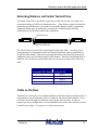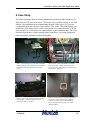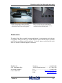
1
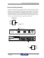
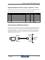
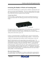
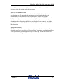
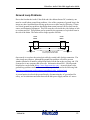
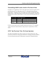
VideoEase Audio-Video Hub Application Guide
VideoEase Audio-Video Hub
p/n 500200
Application Guide
Version 1.03
Feb 2007
©MuxLab
1
VideoEase Audio-Video Hub Application Guide
Purpose
The purpose of this document is to explain how to apply the VideoEase Audio-Video
Twisted Pair Distribution Hub under different operating conditions and to discuss issues
not covered in the Installation Guide that comes with this product.
Function of the Audio-Video Hub
The function of the Audio-Video Hub(500200) is to allow up to two (2) baseband video
and two (2) audio sources to be distributed to eight (8) locations via twisted pair cable.
The Audio-Video Hub may be used in both security surveillance and audio-video
environments. Used in conjunction with MuxLab’s VideoEase video baluns, the AudioVideo Hub provides a more cost-effective total cabling solution via Category 5 twisted
pair cable.
The Audio-Video Hub works in conjunction with the following MuxLab baluns; CCTV
Baluns (500000 & 500009), Stereo Audio-Video Balun (500001), 2-Way Audio-Video
Baluns (500003 & 500012) and S-Video Baluns (500016 & 500017) for a complete twisted
pair cabling solution. By providing a total twisted pair solution; structured cabling system
techniques may be used to managed the connection between the Audio-Video Hub and
the AV equipment for neater wiring and quicker moves, adds and changes.
The following is a list of some of the many applications where the Audio-Video Hub may
be used:
Industrial and Corporate Security and Surveillance
Prison and Correctional Institutions CCTV Security Systems
Traffic Monitoring Systems
Government and Educational Institution CCTV Monitoring
Commercial and Retail CCTV Security Systems
Residential Cabling Systems
Medical Video Information Systems
Video-Conferencing Systems
Hospital Training Systems
Airline Lounge Information Systems
Auditoriums
©MuxLab
2
VideoEase Audio-Video Hub Application Guide
Video-Only Distribution (1 or 2 channels)
The Audio-Video hub may be used to distribute one (1) or two (2) independent video
channels to a maximum of eight (8) locations. For example in the CCTV security
surveillance field, this hub could be used to distribute a monitor output from a video
multiplexer to eight (8) different viewing locations. MuxLab’s CCTV Baluns (500000 or
500009) are used to convert each camera and mux-monitor output to twisted pair. Patch
panels can be used to connect any of the eight identical outputs to any desired UTP outlet
in the building. The following diagram illustrates this:
D
CC
CC
D
CCTV
Baluns
Mux
Cat 3 or Cat 5
CCTV-AV
Hub
Power
Outputs
4
VCR
Monitoring
locations
Parking
©MuxLab
3
VideoEase Audio-Video Hub Application Guide
Composite Video and Stereo Audio Distribution
There are many applications that require a single video and stereo audio source to be
distributed to multiple locations. An example would be of an auditorium where audiovideo presentations are frequently given to large numbers of people. In order to ease
viewing, multiple AV monitors could be installed throughout the auditorium connected
via twisted pair instead of coaxial cable. Using MuxLab’s Stereo Audio/Video Baluns
(500001) and CCTV-Audio-Video Hub (500200), only one (1) Cat 5 twisted pair cable
needs to be brought to each monitor. The connection between the hub ports and each
Cat 5 audio-video outlet could be managed via patch panels in a local wiring closet. The
following diagram illustrates this type of application.
Audio Video
Source
DVD or VCR
Power
Outputs
4
CCTV-AV Hub
(500200)
Stereo Audio
Video Balun
(500001)
Audio
Left
Video
Audio
Right
Cat 5 UTP
©MuxLab
4
VideoEase Audio-Video Hub Application Guide
S-Video Distribution
S-Video is being adopted by schools, hospitals and other institutions as a cost-effective
alternative to the more costly VGA and RGB high-resolution video systems.
The Audio-Video Hub allows up to two (2) video channels to be distributed to up to eight
(8) locations and therefore is perfect for S-Video distribution since it requires two (2)
video channels; luma and chroma. The Audio-Video Hub works in conjunction with
MuxLab’s S-Video Baluns (500016 and 500017) to allow an S-Video source to be
distributed via twisted pair. The 500016 supports S-Video without audio via two (2)
twisted pairs. The 500017 supports S-Video and stereo audio via four (4) twisted pairs;
two (2) pairs for S-Video and two (2) pairs for Left and Right audio channels. Together,
the hub and 500017 supports distribution of S-Video and stereo audio to eight (8)
locations. The following application diagram shows how a single S-Video/Audio source
is distributed to multiple S-Video/Audio monitors in an auditorium situation.
Audio Video
Source
DVD or VCR
S-Video/Audio
Balun (500017)
Power
Outputs
4
CCTV-AV Hub
(500200)
S-Video/Audio
Balun (500017)
Audio
Left
Video
Audio
Right
Cat 5 UTP
©MuxLab
5
VideoEase Audio-Video Hub Application Guide
Reverse Polarity Sensitivity
The Audio-Video Hub works in conjunction with four (4) models of MuxLab VideoEase
Baluns; the CCTV Baluns (500000 & 500009), Stereo Audio-Video Balun (500001), Dual
Audio-Video Baluns (500012) and S-Video Baluns (500016 & 500017). It is important to
note that the Audio-Video Hub is reverse polarity sensitive and that the baluns are pincompatible with the hub. Therefore it is important to ensure that the pin marked “Ring”
on the balun be connected to the pin marked “Ring” on the RJ45 port of the hub. If the
wires are reversed, then either no image or a partial image will be visible.
VideoEase 2-Way
Audio/Video Balun
(500012)
Audio1
Video 1
Audio 2
Cat 5 Twisted Pair
(4-Pair)
Video 2
RJ45
8-pin modular plug
RJ45 Pin Configuration
Video 1:
Video 2:
Audio 1:
Audio 2:
Ring 7 Tip 8
Ring 4 Tip 5
Ring 1 Tip 2
Ring 3 Tip 6
Power
Input
Outputs
Looping Output
NC
GND
+12V
-12V
Power
4
Audio1
Video 1
Audio 2
Video 2
©MuxLab
6
VideoEase Audio-Video Hub Application Guide
Compatibility With Third Party Balun Vendors
The Audio-Video Hub will work with any third party vendor baluns that have the same
pin-configuration and signal polarity as MuxLab’s VideoEase baluns. In order for the
cabling solution to function correctly, it is necessary to ensure that the signal polarity of
other vendors’ videobaluns match up with the MuxLab baluns listed above. When
installing an MuxLab Audio-Video Hub on one end and a third party balun on the other,
verify that the signal polarity is straight-through and not reversed.
©MuxLab
7
VideoEase Audio-Video Hub Application Guide
Equivalent Replacements to Avaya™ Systimax™ Parts
The following table presents the Avaya Systimax products that are functionally equivalent
and compatible with MuxLab’s Audio-Video Hub and VideoEase Baluns:
MuxLab
Part
500000
500009
500001
500012
500016
500017
500200
Description
VideoEase CCTV Modular RJ45 Balun
VideoEase CCTV Screw Terminal Balun
VideoEase Stereo Audio/Video Balun
VideoEase Dual Audio-Video Balun
VideoEase S-Video-Only Balun (Q1 02)
VideoEase S-Video/Audio Balun (Q1 02)
VideoEase Audio-Video Hub
Video
Channels
1
1
1
2
1 S-Video
1 S-Video
2
Audio
Channels
1
1
2
2
2
2
2
Avaya Systimax
Equivalent
380B
None
380A
None
None
None
383A (1 video
signal)
Video Equipment With Built-In Baluns
MuxLab’s Audio-Video Hub will work together with third party equipment that has builtin twisted pair video baluns. Examples of such vendors include Kalatel, Silent Witness
and Intelligent Products. In order to ensure proper operation when using the MuxLab
Audio-Video Hub with these cameras, it is important to verify that the signal polarity is
straight-through and not reversed.
Tip
Blue/White
White/Blue
Ring
C
CCTV-AV Hub
(500200)
Top View
CCTV Camera with
built-in balun
©MuxLab
Ring
White/Blue
Tip
Blue/White
8
VideoEase Audio-Video Hub Application Guide
Increasing the Number of Ports via Cascading Hubs
Several Audio-Video Hubs may be cascaded in order to distribute a baseband audio video
source to up to sixty-four (64) destinations. There are two ways to achieve this; a) using
the Looping Output on the rear of the hub or b) connecting additional hubs to the Output
Ports on the front of the hub creating a hierarchical topology.
Looping Output Method
In the first method, a Looping Output on the rear panel is provided for the purpose of
connecting an adjacent hub. The following picture shows the location of the Looping
Output.
Looping Output
For example an audio video presentation from a VCR or DVD source may be distributed
to multiple classrooms via pre-installed Cat 5 twisted pair cable. Due to the active
electronics in the hub, the maximum number of hubs that may be cascaded is eight (8) at
which point the total number of ports is 64.
*
In order to cascade the first hub to a second hub, prepare a 4-pair Cat 5 cable from the
Looping Output of the first hub to the Input Port of the second hub. The cable must be
configured as straight-through and terminated with RJ45 modular plugs on either end.
Note: The Distribution Ports and Looping Outputs do not amplify the signal. The
maximum distance from the source to the most distant hub or monitor may be up to 2500
feet depending on the type of audio/video signal being transmitted. Please consult the
hub data sheet or installation for distance specifications. The use of patch panels and
punch-down blocks is supported with each cross-connect resulting in an average loss of 5
to 10 feet depending on the type of audio/video signal. For best performance, the patch
panels and punch-down blocks should be Category 5 rated. Furthermore, when splicing
connections onto a punch-down block, ensure that the individual wires remain twisted
right up within ½” of the connection point.
Hierarchical Topology Method
The second method of cascading hubs is to connect secondary hubs to a primary hub in
hierarchical topology. Each of the nine outputs of the primary hub is identical and may
©MuxLab
9
VideoEase Audio-Video Hub Application Guide
be connected to the Input Port of another hub. In the example below, nine (9) hubs (one
primary and eight secondary) may be used to distribute an audio-video source to up to 64
monitors.
VideoEase Stereo
Video Balun (500001)
DVD or VCR
Power
Outputs
4
Cat 5 TP (3-Pair)
Power
Outputs
4
Power
Outputs
Cat 5 TP (3-Pair)
4
Cat 5 TP (3-Pair)
Composite or Component
Audio/Video Monitors
1
Classroom A
8
57
64
Classroom H
Using a Single Hub to Feed Sixteen (16) Monitors
It is possible to use a single hub to feed a single composite video channel to sixteen (16)
monitors. If the video source (V1) is connected to the input, then V1 can be extracted
from the Looping Output port and fed back to the second video channel (V2) of the
primary input port. The primary composite video source will now appear at the V1 and
V2 channels of each output port. This will require a custom RJ45 cable assembly to
assign the twisted pairs to the correct pins on the RJ45.
Please note that V2 may be slightly boosted versus V1 and therefore at short distances
(<100 ft) there may be some wash-out. Inserting a 3 dB attenuator may be necessary. At
longer distances, the cable will attenuate the V2 signal sufficiently to eliminate any washout.
©MuxLab
10
VideoEase Audio-Video Hub Application Guide
Picture Problems
During the installation of the Audio-Video Hub, various picture problems may result. It
is important to know what is causing these problems and how to correct them.
Total Absence of Signal
This problem is almost always due a loss and/or lack of continuity in the connection
between the AV equipment and the Audio-Video Hub. Check the continuity of the
twisted pair link.
Presence of Signal But No Image
This problem is most likely due to a reversal of the polarity of the wires between the
Audio-Video Hub and the video baluns at either the source or destination. MuxLab’s
Audio-Video hub and audio/video baluns are reverse polarity sensitive. The pin
designated as “Ring” must be connected to the pin labeled “Ring” at the other end. For
example if the CCTV Balun (500000) is connected to the Audio-Video Hub, then Pins
7&8 of the RJ45 modular jack at one end must connect to Pins 7&8 respectively at the
other end.
Smearing
Smearing occurs when the edge of an image leaves trail traces similar to smudging a line
of ink on a piece of paper. This may occur as the length of twisted pair cable increases.
As one approaches the maximum specified distance, the physical limitations of the cable
and baluns will become apparent, mainly due to signal propagation delay and attenuation.
Aside from using an active device with a built-in amplifier to correct the problem, the
other possible solutions are; a) to shorten the length of cable or b) adjust the contrast and
brightness of the monitor.
Flutter
Flutter occurs when the background fluctuates between light and dark. This symptom
may be due to problems with the grounding between the CCTV or AV equipment or the
connection may be picking up some external interference from a nearby power
transformer. One way to compensate for this is to adjust the monitor’s contrast and
brightness. Please consult the Audio-Video Hub data sheet for recommended distances
to maintain from sources of external EMI and RFI interference.
Ghosting
Ghosting is characterized by a second video image being received after the main image,
resulting in a double image that is skewed in relation to the first. This is usually due to a
problem with the UTP cable connection itself. Poor crimping, untwisted pairs, some of
the twisted pairs may be longer than others, poor quality cable, exceptionally high
©MuxLab
11
VideoEase Audio-Video Hub Application Guide
crosstalk between the camera and the monitor are all some of the causes. In these cases it
is best to replace the existing cable with a new one.
Loss of Color and Image Detail
Loss of color or image detail may occur if twisted pair cable length exceeds the distance
specifications. As one approaches the maximum specified distance, the physical
limitations of the cable and baluns will become apparent, mainly due to signal
propagation delay and attenuation. Aside from using an in-line amplifier to restore the
signal, one could improve the image by shortening the length of twisted pair or by
eliminating other contributing signal losses such as splices, cross-connects, low-grade
patch cables, etc. A further solution is to double up the twisted pairs as described later in
this document.
Interference Patterns
If a faint moving interference pattern is present, it may be related to noise injected by the
electrical system or by the presence of a ground loop. Sometimes grounding the audio or
video shield to earth ground, the picture may be cleared up. See the next section for
more information about ground loop.
©MuxLab
12
VideoEase Audio-Video Hub Application Guide
Ground Loop Problems
Due to the fact that the Audio-Video Hub and video baluns feature DC-continuity, one
must be careful about ground loop problems. One of the symptoms of ground loop is the
image may have horizontal bars moving up the screen or there may be flickering. If there
is a serious ground loop problem, then higher than normal current will flow between the
source and destination equipment. This will cause the coils inside the video baluns or hub
to overheat and fail. This problem can be spotted by the appearance of a pin-hole burn in
the side of the balun. The balun will no longer operate after this.
CCTV
Balun
Ground Potential
V1
CCTV
Balun
If V1 is higher than V2 then high
current may flow between baluns
Ground Potential
V2
One remedy is to replace the twisted pair cable by coaxial cable for this connection. The
video image may improve, although the ground loop problem will still be present.
Another solution is to install a ground-loop blocker on the line at the receiving end. FM
Systems Inc is one company that offers one. Information about FM’s GB-60 groundloop blocker can be found at http://www.fmsystems-inc.com/. An article about video
ground loop problems and how to correct them may also be found at the following link:
http://www.epanorama.net/documents/groundloop/video_isolation.html
A second option is to break the ground loop by disconnecting the AC ground and for
safety, use an isolation transformer between the hub power supply and the AC source.
©MuxLab
13
VideoEase Audio-Video Hub Application Guide
Transmitting 24VAC and/or Audio In The Same Cable
In regard to CCTV applications, 24VAC and/or audio may be passed on separate twisted
pairs under the same Cat 5 cable jacket as the CCTV video signal without affecting
picture quality. In regard to 24VAC, the voltage level will drop in strength as the cable
length increases. If the voltage drops too low, the camera may not operate. Based on lab
tests performed at MuxLab using a Sanyo CCD color camera, the following results were
obtained:
Cable Length
100 ft
500ft
750 ft
1000 ft
Voltage level
26.70 VAC
24.10 VAC
21.79 VAC
20.50 VAC
Results
Video image unaffected
Video image unaffected
Video image unaffected
Insufficient voltage to power camera
In order to ensure proper results, the installer should check with the CCTV equipment
vendor to determine what the minimum voltage and power requirements are for the
camera.
CCTV “Up-The-Coax” Pan, Tilt, Zoom Systems
The Audio-Video Hub does not support “up-the-coax” pan, tilt, zoom CCTV video
transmission and therefore will not work with MuxLab’s VideoEase PTZ Balun (500007).
For more information about the PTZ Balun please consult the PTZ Balun Data Sheet.
©MuxLab
14
VideoEase Audio-Video Hub Application Guide
Extending Distance via Parallel Twisted Pairs
The Audio-Video Hub is specified to support up to 2200 feet in color via a single Cat 5
twisted pair and up to 2500 feet in black and white. If the distance required exceeds the
maximum specified distance, it is possible to extend the distance further by paralleling
additional twisted pairs, provided spare wire pairs are available and provided the
additional pairs are the same length as the original one.
First twisted pair
Second twisted pair
The effect of this is to lower the overall signal loss due to the cable. In order to avoid
image ghosting, it is important to make sure that all twisted pairs that are paralleled are
exactly the same length. Otherwise any propagation delays introduced by unequal pair
lengths may show up as multiple images on the monitor. Based on calculations done in
MuxLab’s lab, the distance performance that one can expect is shown in the following
table.
Number Pairs Used to
Transmit CCTV Signal
1
2
3
4
Maximum Distance
via Cat 5 UTP
2200 ft.
2684 ft.
2904 ft.
3432 ft.
Cable on the Reel
Sometimes it is necessary to test a balun installation with some spare twisted pair cable. It
is important to note that when the cable is on the reel, the picture will be inferior. This is
due to the increased magnetic induction created by the spool of cable. In order to
properly pre-test a configuration, it is recommended to un-coil the cable and lay it out flat
on the floor in a figure “8” pattern or in a cable farm structure.
©MuxLab
15
VideoEase Audio-Video Hub Application Guide
Multiple AV Signals Under One Cable Jacket
Multiple AV signals may be transmitted under a single Category 5 cable jacket. As long
as the cable is rated Category 5 or better, the number of pairs may be 4, 25, 50, 100 or
200). The rating of Category 5 ensures that performance is adequate enough to prevent
CCTV signals from interfering with each other under the same cable jacket. To locate
sources for multi-pair Cat 5 cable, please contact your local cable and connector vendor.
Cable Types Supported
The Audio-Video Hub will work with lower grades of cable such as Category 3 or
Category 2. The maximum specified distance will be considerably shorter than with
Category 5. Please consult the Audio-Video Hub Product Data Sheet or Installation
Guide for maximum distance specifications.
In outdoor applications, outside Cat 5 cable is recommended. Cable vendors typically
sell different types of outdoor cable. Information about Mohawk/CDT outdoors Cat 5
cable may be found at http://www.mohawk-cdt.com/prod/lan-10.html
RGB Video
The Audio-Video Hub will only support Composite and S-Video. It will not support
RGB. In order to distribute RGB via Cat5 UTP, it is recommended to use a coax-based
RGB distribution amplifier such as the Altinex DA1226AT
(http://www.altinex.com/PDFs/DA/DA1226AT.pdf ) and connect the RGB Balun (500002) or
three (3) of the CCTV Baluns (500009) to each port.
Digital Multiplexers
Some video multiplexers introduce additional signal loss in the course of digitizing and
processing the incoming analog camera signal. Consequently, the maximum distance
achievable between the camera and the multiplexer will be shorter than with standard
analog-based multiplexers. Based on actual results in the field, a maximum of 800 feet
seems to be achievable when used with these muxes, versus 2200 feet with analog muxes.
In order to extend the distance beyond 800 feet, an active balun transmitter or receiver
must be used.
©MuxLab
16
VideoEase Audio-Video Hub Application Guide
Scan Converters
In regard to the use of scan converters with the 500200, it is recommended to test the scan
converter with the 500200 before using it. Some scan converters generate better quality
composite video output than others and therefore when used with the 500200, better
results may be achieved depending on the model of scan converter.
MuxLab has tested two (2) models of scan converters with the 500200; GrandTec XP Pro
and SB-3800 PC to TV Converter. When tested with S-Video, the GrandTech XP Pro
was found to give poor results with significant image distortion and smearing even at
short distances. However, the SB-3800 gave good results with no distortion and smearing
even at long distance. Fmore information about the SB-3800 please refer to the following
link: http://www.celakovice.cz/~gemos-cz/f.htm
©MuxLab
17
VideoEase Audio-Video Hub Application Guide
A Case Study
The following images illustrate a demo installation performed by FM Electronics (Cle
Elum,WA) at a US west coast school. The images were provided courtesy of Mr. Fred
Marion. The installation involved distributing an audio-video source (VCR) to one
overhead projector and one audio-video monitor. The Audio-Video Hub(500200) was
installed in a local wiring closet. Audio-video baluns were connected to the VCR and
projector and Cat 5 twisted pair was connected back to the distribution hub. The client
liked the fact that there were no exposed cables on the floor. All wiring disappeared
under raised floor partitions or behind wall outlets.
Photo 1: Overhead projector connected to videobalun
(MuxLab 500012). Cat 5 cabling is then routed from
balun under raised floor partition back to wiring
closet.
Photo 2: Audio-Video Hub (500200) is installed in
local wiring closet. Outputs from two ports are
connected to the overhead projector and audio-video
monitor in the classroom.
Photo 3: View of the overhead projector and audiovideo monitor. Note the absence of exposed
audio-video cables on the floor.
Photo 4: Close-up image of the audio video baluns
connected to a piece of audio-video equipment.
Note that one video and two audio channels are
being converted to three (3) pairs of Cat 5 UTP.
(MuxLab 500012)
©MuxLab
18
VideoEase Audio-Video Hub Application Guide
Photo 5: Close-up image of the rear panel of the
Audio-Video Hub (500200). The input of the hub is
connected to the audio-video source equipment.
Photo 6: Close-up of the Cat 5 cable exiting the
overhead projector and feeding through an opening
in the floor to return to the wiring closet.
Conclusion
The Audio-Video Hub is suitable for many applications. It is important to verify the type
of equipment being used, the type of cable, distance required and the picture resolution
needed before proceeding with an installation. If in doubt, please contact MuxLab Inside
Sales or Customer Technical Support for assistance.
MuxLab Inc.
8114 Transcanada Hwy
St. Laurent (Quebec)
Canada H4S 1M5
©MuxLab
Telephone : ......................................514-905-0588
Toll-free (North America) : ........ 1-877-689-5228
Fax : .................................................514-905-0589
E-mail:
[email protected]
URL:
www.muxlab.com
19