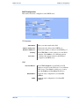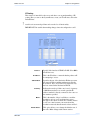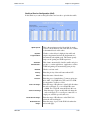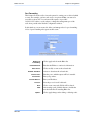
1
Revision: 1.0
Firmware: 2.0.18
Date: 31/08/06
Document Revisions:
Version 1.0
December, 2006
Orbitel Telecom. e Inform. Ltda.
SIG QUADRA O3 Bl. B No. 99 Sala 101
Brasília – DF – Brasil – 70610-400
Tel: 61 3031-4100
Fax: 61 3344-4101
iiiiii
This document is intended for Public Distribution
Pitt Meadows, B.C. Canada V3Y 2V4
General Inquiries: mailto:[email protected]
Sales: [email protected]
Technical Support: [email protected]
19473 Fraser Way,
ii
Orbitel Telecom
Safety Information
Safety Information
FCC Compliance
This device has been tested and found to comply with the limits for a Class B digital device
pursuant to Part 15 of the FCC rules. These limits are designed to provide reasonable
protection against harmful interference when the device is operated in a residential
environment. This device generates, uses, and can radiate radio frequency energy. If not
installed and used in accordance with the user guide, may cause harmful interference to radio
communication. In case of harmful interference, the users will be required to correct the
interference at their own expense.
The users should not modify or change this device without written approval from Orbitel
Wireless. Modification will void warranty and authority to use the device.
For safety reasons, people should not work in a situation where RF exposure limits could be
exceeded. To prevent this situation, the users should consider the following rules:
•
•
•
•
•
Install the antenna so that there is a minimum of 23 cm (9.06 in) of distance between
the antenna and people.
Do not turn on power to the device while installing the antenna.
Do not connect the antenna while the device is in operation.
Do not collocate or operate the antenna used with the device in conjunction with any
other antenna or transmitter.
In order to ensure compliance with local regulations, the installer MUST enter the
antenna gain at the time of installation. See Chapter 3: Wireless Settings, for details.
Nota ANATEL
“Este equipamento opera em caráter secundário, istoé, não tem direito a proteção contra interferência
prejudicial, mesmo de estações do mesmo tipo, e não pode causar interferência a sistemas operando em
caráter primário”
OBT-954
Pitt Meadows, B.C. Canada V3Y 2V4
iiiiiiiii
This document is intended for Public Distribution
19473 Fraser Way,
iii
Orbitel Telecom
!
Safety Information
Safety Instructions
You must read and understand the following safety instructions before installing the device:
•
•
•
•
•
This antenna’s grounding system must be installed according to Articles 810-15,
810-20, 810-21 of the National Electric Code, ANSI/NFPA No. 70-1993. If you have
any questions or doubts about your antenna’s grounding system, contact a local
licensed electrician.
Never attach the grounding wire while the device is powered.
If the ground is to be attached to an existing electrical circuit, turn off the circuit before
attaching the wire.
Use the Orbitel Power over Ethernet (POE) adapter only with approved Orbitel
models.
Never install radio equipment, surge suppressors or lightning protection during a storm.
Lightning Protection
The key to lightning protection is to provide a harmless route for lightning to reach ground. The
system should not be designed to attract lightning, nor can it repel lightning. National, state and
local codes are designed to protect life, limb, and property, and must always be obeyed. When
in doubt, consult local and national electrical codes or contact an electrician or professional
trained in the design of grounding systems.
Professional Installation Required
The product requires professional installation. Professional installers ensure that the
equipment is installed following local regulations and safety codes.
To reduce potential radio interference to other users, the antenna type and its gain should be
so chosen that the equivalent isotropically radiated power (e.i.r.p.) is not more than that
permitted for successful communication.
OBT-954
Pitt Meadows, B.C. Canada V3Y 2V4
iviviv
This document is intended for Public Distribution
19473 Fraser Way,
iv
Orbitel Telecom
Table of Contents
Table of Contents
Chapter 1: Overview ........................................................................ 1-1
Introduction ...................................................................................................... 1-1
Product Kit ....................................................................................................... 1-1
Product Description .......................................................................................... 1-1
LED Panel Indicators................................................................................... 1-2
Chapter 2: Hardware Installation ...................................................... 2-1
Getting Ready ................................................................................................... 2-1
Tools Required............................................................................................. 2-1
Site Selection ............................................................................................... 2-1
Polarity......................................................................................................... 2-2
Power Supply ............................................................................................... 2-2
Installing the Ethernet Cable ............................................................................ 2-3
Mounting the Radio .......................................................................................... 2-5
Grounding the Antenna .................................................................................... 2-5
Connecting the Radio ....................................................................................... 2-6
Best Practices ................................................................................................... 2-7
Chapter 3: Configuration................................................................... 3-1
Connecting to the Radio ................................................................................... 3-1
Changing the IP Address - Windows XP .................................................... 3-1
Changing the IP Address Using the Orbitel Locator ................................. 3-2
Login into the Configuration Interface............................................................. 3-3
Information Page .............................................................................................. 3-4
Setup Menu....................................................................................................... 3-5
Wireless Settings ......................................................................................... 3-5
Administrative Settings ............................................................................... 3-8
WDS ............................................................................................................ 3-9
Security........................................................................................................... 3-10
Basic Security Settings .............................................................................. 3-10
Advanced Security Settings ....................................................................... 3-11
Access Control ........................................................................................... 3-12
Status .............................................................................................................. 3-13
AP List ....................................................................................................... 3-14
ARP Table ................................................................................................. 3-14
Statistics ..................................................................................................... 3-15
System Performance .................................................................................. 3-17
OBT-954
Pitt Meadows, B.C. Canada V3Y 2V4
vvv
This document is intended for Public Distribution
19473 Fraser Way,
v
Orbitel Telecom
Table of Contents
Network Configuration................................................................................... 3-18
Bridge Mode .............................................................................................. 3-18
Router Mode .............................................................................................. 3-19
DHCP Configuration ................................................................................. 3-21
IP Routing .................................................................................................. 3-22
Quality of Service Configuration (QoS) .................................................... 3-23
Port Forwarding ......................................................................................... 3-24
Port Filtering .............................................................................................. 3-25
Appendix A: Grounding and Lightning Protection Information .... A-1
Appendix B: Quality of Service Configuration (QoS) ..................... B-1
Appendix C: Protocol List ................................................................. C-1
Appendix D: Common TCP Ports ..................................................... D-1
Appendix E: Channel Allocations .................................................... E-1
Appendix F: Wiring Standard ........................................................... F-1
OBT-954
Pitt Meadows, B.C. Canada V3Y 2V4
vivivi
This document is intended for Public Distribution
19473 Fraser Way,
vi
Orbitel Telecom
Chapter 1: Overview
Chapter 1: Overview
Introduction
This next-generation wireless LAN device–the Orbitel OBT-954– brings Ethernetlike performance to the wireless realm. Fully compliant with the IEEE802.11a
standard, the OBT-954 also provides powerful features such as the Internet-based
configuration utility as well as WEP and WPA security.
Product Kit
The OBT-954 product kit contains the items shown below. If any item is
missing or damaged, contact your local dealer for support.
OBT-954
device x 1
Ethernet boot
cover x 1
Mounting bracket x 1
Gasket x 1
Strain relief x 1
Keps nuts x 8
DC power
adapter x 1
U-bolt w/ 2 nuts x 1
Lock washers x 2
POE adapter x 1
Product Description
The LEDs, ports and product information are located at the back of the TR-900
Series radio, as shown in the picture.
LED Panel indicators
Serial number
MAC address
OBT-954
Pitt Meadows, B.C. Canada V3Y 2V4
111
This document is intended for Public Distribution
19473 Fraser Way,
Ethernet ports
Studs for the boot
cover
Studs for the
mounting bracket
1-1
Orbitel Telecom
Chapter 1: Overview
LED Panel Indicators
Label
Power
LAN
Radio
Signal
(CPE Mode)
Color
Red
On: Powered on
Off: No power
Green
On: Ethernet link
Flashing: Ethernet traffic
Off: No Ethernet link
Amber
On: Radio link
Flashing: Radio activity
Off: No radio link
Red
Amber
Green
Label
Signal
(AP Mode)
OBT-954
Pitt Meadows, B.C. Canada V3Y 2V4
Indicators
Color
In CPE mode (Client Premises Equipment),
light up in sequence to indicate signal
strength.
Indicators
Red
On: WEP/128 enabled
Flashing: WEP/64 enabled
Off: WEP off
Amber
On: WPA/AES enabled
Flashing: WPA/TKIP enabled
Off: WPA off
Amber
Flashing: AP Mode
Green
On: ACL enabled
Off: ACL off
Green
On: WDS enabled
Off: WDS off
222
This document is intended for Public Distribution
19473 Fraser Way,
1-2
Orbitel Telecom
Chapter 2: Hardware Installation
Chapter 2: Hardware Installation
The OBT-954 radios are easy to install, as you’ll see in this chapter. Before
starting, you will need to get the tools listed below and decide about the site and
orientation of the device. Once ready, follow the instructions about how to install
the Ethernet cable, mount the device, ground the antenna, and make the
connections in order to get a proper installation.
Getting Ready
Tools Required
To install your OBT-954 radio you will need the following tools:
•
•
•
•
•
•
•
•
1/2” wrench x 1
3/8” wrench x 1
Cat 5 cable stripper x 1
Cat 5 cable (to connect the radio to the POE adapter)
RJ-45 patch cable
RJ-45 crimper x 1
RJ-45 connectors x 4
#6 green grounding wire
Site Selection
Determine the location of the radio before installation. Proper placement of the
device is critical to ensure optimum radio range and performance. You should
perform a site survey to determine the optimal location.
Ensure the CPE is within line-of-sight of the access point. The line-of-sight is an
ellipse, called Fresnel zone. This zone should be clear of obstacles since
obstructions will impede performance of the device.
Fresnel zone
OBT-954
Pitt Meadows, B.C. Canada V3Y 2V4
111
This document is intended for Public Distribution
19473 Fraser Way,
2-1
Orbitel Telecom
Chapter 2: Hardware Installation
Polarity
Determine if the antenna’s polarization will be horizontal or vertical before
installation. The TR-900 radios can be used in either polarity. The Ethernet boot
cover should always be placed so that the cable runs toward the ground for
maximum environmental protection.
Power Supply
Only use a power adapter approved for use with the OBT-954 radio. Otherwise,
the product may be damaged and will not be covered by the Orbitel warranty.
OBT-954
Pitt Meadows, B.C. Canada V3Y 2V4
222
This document is intended for Public Distribution
19473 Fraser Way,
2-2
Orbitel Telecom
Chapter 2: Hardware Installation
Installing the Ethernet Cable
Step 1:
Insert the strain reliefinto the port opening
of the boot cover.
Step 2:
Using a 3/4” wrench, tighten the strain
relief until it touches the boot cover.
IMPORTANT! Use hand tools only. Do
not over tighten.
Step 3:
Put the cap nut back over the strain relief
and insert the Cat 5 cable through it. Wire
the cable following the EIA/TIA T568B
standard, and attach the RJ-45 connectors
to each end of the cable. (See Appendix F:
Wiring Standard).
Step 4:
If you purchased the device with a dual
port cover, repeat steps 1, 2, and 3 for the
second port.
IMPORTANT! If you are not going to use
the second port, insert the strain relief into
the boot cover and tighten the cap nut to
ensure a weather-tight seal, as shown in the
picture.
OBT-954
Pitt Meadows, B.C. Canada V3Y 2V4
333
This document is intended for Public Distribution
19473 Fraser Way,
2-3
Orbitel Telecom
Chapter 2: Hardware Installation
Step 5:
Place the gasket—with the adhesive side
facing up—over the 4 studs around the port
of the radio. Flatten the gasket ensuring
there are no gaps. Remove the backing.
Step 6:
Plug the Cat 5 cable inserted in the boot
cover into the port. Remember to place the
boot cover according to the desired
polarization, so that the strain relief faces
the ground.
Step 7:
Fit the boot cover over the 4 studs and the
gasket. Secure with 4 keps nuts. Tighten
with a 3/8” wrench until the gasket is at
least 50% compressed.
Step 8:
Make sure the cap nut of the strain relief is
tightened properly to ensure a weatherproof seal.
IMPORTANT! Hand tighten only. Do not
over tighten as you may damage the
weather-tight seal of the strain relief.
OBT-954
Pitt Meadows, B.C. Canada V3Y 2V4
444
This document is intended for Public Distribution
19473 Fraser Way,
2-4
Orbitel Telecom
Chapter 2: Hardware Installation
Mounting the Radio
Step 9:
Attach the mounting bracket to the pole
using the U-bolt. Secure the U-bolt with
the lock washers and the nuts. Align if
necessary, and then tighten the nuts enough
to prevent any movement.
Step 10:
Fit the radio to the mounting bracket.
Secure the radio with keps nuts.
IMPORTANT! The strain relief must be
always facing the ground.
Grounding the Antenna
Step 11:
Using a #6 green grounding wire, connect
the grounding lug on the radio to a proper
ground. See Appendix A: Grounding and
Lighting Protection Information.
!
IMPORTANT: This device must be grounded. Connect the green grounding wire
to a known good earth ground, as outlined in the National Electrical Code. See
Appendix A: Grounding and Lightning Protection Information for details.
OBT-954
Pitt Meadows, B.C. Canada V3Y 2V4
555
This document is intended for Public Distribution
19473 Fraser Way,
2-5
Orbitel Telecom
Chapter 2: Hardware Installation
Connecting the Radio
Step 12:
Connect the Cat 5 cable from the radio into
the RJ-45 jack marked “CPE” on the POE
adapter. The POE adapter is not weatherproof and should be installed indoors.
Step 13:
Connect the power adapter to the POE
adapter and plug the other end to an outlet.
The POE adapter will be powered on and
the power indicator on the top panel will
turn on. We recommend to connect the
power adapter to an outlet with surge
suppression capability with an uninterrupted
power supply (UPS) for reduced outages.
IMPORTANT! Use the power adapter
supplied with the radio. Otherwise, it may
be damaged.
Step 14:
To configure the OBT-954 radio, connect
the Ethernet cable to the POE adapter and
to a computer. Ensure that the distance
between the computer and the radio does
not exceed 300 ft (90 m).
Note: If connecting to a hub or switch, a
crossover cable may be required.
OBT-954
Pitt Meadows, B.C. Canada V3Y 2V4
666
This document is intended for Public Distribution
19473 Fraser Way,
2-6
Orbitel Telecom
Chapter 2: Hardware Installation
Best Practices
Follow these practices to ensure a correct installation and grounding.
•
•
•
•
•
Always try to run long Cat 5 and LMR cables inside of the mounting pole.
This helps to insulate the cable from any air surges.
Keep all runs as straight as possible. Never put a loop into the cables.
Test all grounds to ensure that you are using a proper ground. If using an
electrical socket for ground, use a socket tester, such as Radio Shack 22-141.
Keep a copy of the National Electrical Code Guide at hand and follow its
recommendations.
If you are in doubt about the grounding at the location, drive your own rod
and bond it to the house ground. At least you will know that one rod is
correct in the system.
OBT-954
Pitt Meadows, B.C. Canada V3Y 2V4
777
This document is intended for Public Distribution
19473 Fraser Way,
2-7
Orbitel Telecom
Chapter 3: Configuration
Chapter 3: Configuration
The OBT-954 radios can be configured through an HTML configuration
interface, accessible using any Internet browser. The configuration interface
allows you to define and change settings, and also shows information about the
performance of the device.
In this chapter we’ll cover how to access the configuration interface, configure the
OBT-954 radio, and interpret the information displayed in the interface. Depending
on whether the device is defined as an AP or CPE (infrastructure station), some
menu options, windows, and fields in the interface may vary or may not appear at
all. We’ll indicate so when describing each window.
Connecting to the Radio
Before accessing the configuration interface, you have to change the network
connection settings in your computer to be on the same subnet as the radio.
Changing the IP Address - Windows XP
1. In your computer, open Control Panel > Network Connections > Local Area
Connection.
2. In Local Area Connection Status > General, click Properties.
3. In Local Area Connection Properties > General, select Internet Protocol
(TCP/IP) and click Properties.
4. In Internet Protocol (TCP/IP) Properties > General, select Use the following
IP address.
5.
Enter your IP address and Subnet Mask. The default IP address of the radio
is 192.168.1.100, which cannot be used here.
6.
Click OK and Close.
OBT-954
Pitt Meadows, B.C. Canada V3Y 2V4
111
This document is intended for Public Distribution
19473 Fraser Way,
3-1
Orbitel Telecom
Chapter 3: Configuration
Changing the IP Address Using the OrbitelLocator
The Orbitel Locator is a utility that allows users to quickly change the IP address of
the Orbitel radios. It sends out a broadcast on the network and displays a list of other
Orbitel radios connected, from which you can configure the IP address for your
device.
Note: The Locator cannot locate radios through routers.
The Orbitel Locator displays the following options:
Scan:
Configure:
Upgrade:
Web:
Auto IP:
Locates Orbitel radios connected to the network. A
yellow icon appears before the name when the radio is
not in the same subnet.
Used to set a static IP address or set the radio into
DHCP mode.
Under development.
Opens a browser to access the configuration interface.
To automatically set the radio to an IP address one
number higher than the IP address of the computer.
Find the latest version of the Orbitel Locator at www.Orbitel.com.br, under Orbitel
Suporte > Download de arquivos > Utilitários.
Pitt Meadows, B.C. Canada V3Y 2V4
OBT-954
222
This
docu
ment
is intended for Public Distribution
19473 Fraser Way,
3-2
Orbitel Telecom
Chapter 3: Configuration
Login into the Configuration Interface
After defining the network settings, follow these steps to login into the Orbitel
Configuration Interface.
1. Open your Internet browser (Internet Explorer, Netscape, or Firefox).
2. In the address bar, type your IP address (default IP: http://192.168.1.100).
3. In the login dialog, enter your Username and Password (if you’re a firsttime user, follow the instructions below).
4.
Click OK. You will then access the configuration interface.
If you’re a first-time user:
1. Enter the default username admin and the default password default.
2. In the Password Set/Reset window, change the Administration and
Recovery* passwords. They cannot be left as default and must be different
from each other. You can change the usernames too.
3.
Click Apply to save the changes.
4. You will be prompted to enter your new username and password in the login
dialog. You will then access the configuration interface.
* The recovery username and password are used to access the Password Set/Reset
window if the administration password is lost.
OBT-954
Pitt Meadows, B.C. Canada V3Y 2V4
333
This document is intended for Public Distribution
19473 Fraser Way,
3-3
Orbitel Telecom
Chapter 3: Configuration
Information Page
This is the first window of the configuration interface. It shows the main menu and
information about the device settings, like wireless, network, and security settings.
The menu is divided in four sections:
•
Setup Menu
•
Security
•
Status
•
Network
Each section contains navigation links to the configuration windows, some of
which may be different for access points and CPEs.
Information Page - AP
Information Page - CPE
OBT-954
Pitt Meadows, B.C. Canada V3Y 2V4
444
This document is intended for Public Distribution
19473 Fraser Way,
3-4
Orbitel Telecom
Chapter 3: Configuration
Setup Menu
In this section you would be able to configure wireless and administrative settings
for the OBT-954 radio.
Wireless Settings
This window displays the wireless configuration of the device. The contents are
slightly different for access point and CPE.
Wireless Mode:
SSID:
Visibility Status*:
Define if your device will operate as Infrastructure
Station (CPE) or Access Point.
The Service Set Identifier (SSID) is the name that
identifies a specific wireless LAN. Devices must have
the same SSID to communicate with each other. In
Infrastructure Station mode (CPE), you can enter
primary and secondary SSIDs when using two access
points in the network. Clients will connect to the
secondary access point when the primary is
unavailable or goes down.
You can set your access point to be Visible or
Invisible to clients.
Channel Width:
Select the Channel Width you will be using
Channel Mode:
Select the mode that the channel will use. Pure b
mode, pure g mode, or mixed b/g mode.
Select the channel that the access point and clients use.
The transmission speed at which the radio and access
point communicate with each other.
Note: Setting this rate below the maximum possible
does not limit bandwidth and often has a negative
impact on the operation of your network.
* Feature available only in access point wireless mode.
Channel*:
TX Rate:
OBT-954
Pitt Meadows, B.C. Canada V3Y 2V4
555
This document is intended for Public Distribution
19473 Fraser Way,
3-5
Orbitel Telecom
Chapter 3: Configuration
RTS Threshold:
This is the maximum size for a packet to be sent
automatically. When it exceeds the RTS threshold, the
CPE sends first a ‘request to send’ (RTS) to the access
point before sending the packet.
Note: The more clients you have, the lower the value
should be set.
Fragmentation
Threshold:
This is the size at which packets are fragmented in
order to be transmitted. Setting this value too low
decreases the amount sent on each transmission. In
noisy areas, this can improve performance. However,
in quiet areas, this will decrease throughput.
Link Distance:
This is the distance between the CPE and access point.
This setting is necessary to define the correct ACK
timing. Setting this value too low or too high will result
in low throughput and high retries.
ACK Timeout Tuning:
The time that the radio waits for an acknowledgment
(ACK) from the access point accepting transmission
before re-attempting to send the data. This is an offset
from the ACK timing set by the link distance.
Beacon Interval*:
This is the rate at which the access point broadcasts its
beacons.
DTIM Interval*:
The DTIM interval (Delivery Traffic Indication
Message) helps to keep marginal clients connected by
sending wake up frames.
Burst Time*:
802.11d Enabled*:
This allows to send data without stopping. Note that
other wireless devices in the network will not be able
to transmit data for this number of microseconds.
Check to operate in 802.11d mode. This mode is not
used in USA or Canada.
PxP Mode:
Follow the instructions in next page.
PxP Mac Address:
Follow the instructions in next page.
Block Inter-Client
Traffic*:
Power Cap:
Country:
Antenna Gain:
Preamble:
Check to block wireless communications between
clients on the access point.
It is the maximum output power of the radio.
Select the country where the device is located. Setting
an incorrect country may be considered a violation of
the applicable law, as rules differ in each country.
Select the gain of the antenna. This information must
be set by the installer at the time of installation.
Select type: Long uses long preamble only, Auto
(recommended) tries short preamble first, then long.
* Feature available only in access point wireless mode.
OBT-954
Pitt Meadows, B.C. Canada V3Y 2V4
666
This document is intended for Public Distribution
19473 Fraser Way,
3-6
Orbitel Telecom
Chapter 3: Configuration
To operate the radio in PxP mode:
1. Set one radio to Access Point and the other to Infrastructure Station.
2. Enter the same SSID on both radios.
3.
Set the Channel on the access point.
4. On both radios, enter the Mac address of the opposite radio in the PxP Mac
Address field (no colons).
5.
Check off PxP Mode Enabled.
Note:
> In PxP mode, the LEDs on the radios will operate the same as in Infrastructure
Station mode, with LEDs proportional to signal strength.
OBT-954
Pitt Meadows, B.C. Canada V3Y 2V4
777
This document is intended for Public Distribution
19473 Fraser Way,
3-7
Orbitel Telecom
Chapter 3: Configuration
Administrative Settings
Use this window to upgrade the software, change your password, and define
SNMP parameters.
Upgrade Software:
Defaults:
Reboot:
Rollback:
Device Name:
User Name:
Password:
Enter the location of the software update file or Browse
to locate it in your computer. Click Upgrade Software.
If the radio does not refresh the Information Page after
1 minute, press Refresh, Reload or F5. Verify the new
firmware is installed correctly.
Returns all settings to factory defaults, including
passwords.
Restarts the system without changing settings.
To undo the most recent change.
It is the network name of the device. This name appears
in the Locator and on the Orbitel stations list.
This is the login username.
Enter a new password if you want to change it.
Confirm Password:
Re-type the new password.
Extended Wireless
Information:
Enables extended information (name and IP address),
which is only displayed with Orbitel access points.
Signal/Status LEDs:
SNMP Parameters:
OBT-954
Pitt Meadows, B.C. Canada V3Y 2V4
Un-check to turn off the LED panel indicators.
Here you set the Read Community string and
Contact/Location information. It’s highly
recommended that you change the Read Community
string immediately to prevent unauthorized scanning
of your network.
888
This document is intended for Public Distribution
19473 Fraser Way,
3-8
Orbitel Telecom
Chapter 3: Configuration
WDS (AP only)
The Wireless Distribution System (WDS) is a modification to the 802.11 standards that allows access points to communicate directly with each other. WDS
allows users to spread out coverage to a larger area without the need for a
backhaul link. The tradeoff is that overall throughput is greatly affected for all
users of the access points linked.
WDS is not recommended for use with large numbers of clients or when throughput
needs to be maximized. In both cases, a dedicated PxP link should be used.
However, in areas of low density, WDS can allow an ISP to extend coverage into an
area at very low cost.
To set up WDS:
1.
Select Enabled to activate WDS and click Apply.
2. Go to the Administrative Settings window and change the settings to
Defaults.
3. Go to the Wireless Settings window and set the same Channels for both
access points.
4. In the WDS settings window, enter the Mac address of the peer. Do not
insert colons or commas.
5.
Click Apply.
Note:
> WDS links don’t appear in the Station List or Performance windows. To
monitor the link’s strength and performance, use PxP mode.
> Throughput is cut by 50% per link.
> WDS does not support WPA encryption.
> All links need to be on the same channel.
OBT-954
Pitt Meadows, B.C. Canada V3Y 2V4
999
This document is intended for Public Distribution
19473 Fraser Way,
3-9
Orbitel Telecom
Chapter 3: Configuration
Security
In this section you can configure both basic and advanced security settings for
your device.
Basic Security Settings
In this window you can define WEP parameters. WEP provides security by
encrypting data so that it’s protected when transmitted from one point to another.
Enabled:
Check to turn on WEP security protocol.
Authentication:
Select your system to be open or shared. Open is
always recommended.
Key Length:
This is the level of encryption. Note that 64 bit is
referred to as 40 bit on some systems.
Default Key:
Select the default WEP key from the list.
Activate Keys:
OBT-954
Pitt Meadows, B.C. Canada V3Y 2V4
Enter the four WEP keys you want to activate. Keys
must be entered in HEX only.
101010
This document is intended for Public Distribution
19473 Fraser Way,
3-10
Orbitel Telecom
Chapter 3: Configuration
Advanced Security Settings
In this window you can enter WPA parameters. WPA provides a higher level of
security, enhancing the security features of WEP.
Enabled:
Cipher Type:
PSK:
Check to turn on WPA.
Select the level of encryption.
Enter your PSK password.
Update Interval:
This is the interval at which the PSK password will be
updated.
Authentication:
Ensures that only authorized network users can access
the network. Enter the information about the RADIUS
server from your Internet Service Provider.
OBT-954
Pitt Meadows, B.C. Canada V3Y 2V4
111111
This document is intended for Public Distribution
19473 Fraser Way,
3-11
Orbitel Telecom
Chapter 3: Configuration
Access Control (AP only)
This feature allows you to control the accessibility from wireless devices, in other
words, to allow or deny access from other radios. It applies only to devices working
as access points.
Enable Access
Control:
Edit Mode:
Authorized Station
Devices:
Enable to control accessibility from wireless devices.
Check to make changes in access control settings.
This is the list of the authorized devices. To change
current settings, check the devices and click Copy All
or Copy Selected. The devices will appear in the Mac
Address box on the right.
Note: If you are working via a radio link, add first the
address of the station you are connecting from.
Otherwise, you will be locked out of the radio.
Available Station
Devices:
This list contains the devices available but not
authorized. To authorize them, check the devices and
click Copy All or Copy Selected. The devices will
appear in the Mac Address box on the right.
Manually Authorize
Stations:
In this box you can perform different actions like
authorize, deauthorize and delete devices listed here.
OBT-954
Pitt Meadows, B.C. Canada V3Y 2V4
121212
This document is intended for Public Distribution
19473 Fraser Way,
3-12
Orbitel Telecom
Chapter 3: Configuration
Status
This section displays information about the status and performance of your radio.
Most options and information cannot be modified in this section.
Stations List (AP only)
This window displays a list of the stations associated with the access point and
their connection statistics.
Name:
Mac Address:
Address:
OBT-954
Pitt Meadows, B.C. Canada V3Y 2V4
This information appears here when the device is a
Orbitel 6000 and the Extended Wireless Information
option in the Administrative Settings window is
checked. Otherwise, the field will be blank. You can
manually enter a name by left clicking on the field and
typing in. However, if the Extended
Wireless Information option is turned on at the client,
the name you entered will be overwritten with the name
on the client.
The Mac addresses of the associated stations. IP
Works as with the Name. It appears when the
Extended Wireless Information option in the
Administrative Settings window is checked.
Status:
Indicates if the station is associated or WDS BSSID.
Signal:
This is the radio frequency power in dBm as detected at
the access point. A strong link is defined by both the
AP signal and the client signal. Links should also be at
least 10 dB higher than the receive sensitivity of the
weakest element or the noise floor, whichever is higher,
on both sides.
Speed:
This is the radio speed of the link. Speed is based on
both signal strength and the quality of the link. If the
link is losing a lot of packets due to poor Fresnel zones
or interference, the speed will be lower than the strength
can support.
131313
This document is intended for Public Distribution
19473 Fraser Way,
3-13
Orbitel Telecom
Chapter 3: Configuration
AP List (CPE only)
This window displays information about the access points associated with the CPE
and the connection statistics.
You can set an access point’s SSID as your primary SSID by clicking on the MAC
address when it’s displayed as a link. This will automatically reboot the radio.
ARP Table
This table lists the devices that have communicated with your device via TCP.
There should be a limited number of entries in this table, especially if the
interstation blocking is turned on at the access point.
OBT-954
Pitt Meadows, B.C. Canada V3Y 2V4
141414
This document is intended for Public Distribution
19473 Fraser Way,
3-14
Orbitel Telecom
Chapter 3: Configuration
Statistics
This section is divided in 3 windows: LMAC (Lower Mac), UMAC (Upper Mac),
and Ethernet, which can be accessed from the Statistic Summary Page.
LMAC Statistics
The LMAC functions occur in the radio chipset. While the UMAC divides the
statistics into clean and failed packets, LMAC defines why packets failed.
This window contains three tabs: TX, RX and INT. TX and RX values are useful
to ISPs and other users. The INT (internal) statistics are intended for use by
Orbitel Wireless Technical Support.
You can click onto each speed level and see how the traffic breaks down. In the TX
statistics, there should little to no Tries at Series 2, 3 or 4. The radio will try to send
a packet 4 times at Series 1 and then will try the next series 4 times. In the RX
statistics, you should look for bad CRCs and bad decrypts for signs of RF
interference or Fresnel interference links. Bad PHYs generally are caused when the
radio is unable to decode the packets due to noise.
Note:
Communication between access points and CPEs always occurs at the lowest rate.
In a normal link, you should see a fair number of transactions at the lowest rate.
OBT-954
Pitt Meadows, B.C. Canada V3Y 2V4
151515
This document is intended for Public Distribution
19473 Fraser Way,
3-15
Orbitel Telecom
Chapter 3: Configuration
UMAC Statistics
The UMAC functions occur in the unit’s processor. The UMAC statistics are
likely the most useful for radio troubleshooting. This window breaks down the
statistics into clean and failed packets.
The failed packets should be less than 10% in a normal operating environment. In
the TX statistics, there should be little to no Retransmits at Series 2, 3 or 4. Life
Statistics are reset on each reboot.
Ethernet Statistics
In this window, excessive collisions are usually a sign that the radio and the device it
is linked to are not on the same duplex settings. One is at full while the other is
at half. Try locking both to the same values.
Collisions do normally occur on an Ethernet network and are generally handled by
the Carrier Sense Multiple Access with Collision Detect (CSMA/CD) mechanism.
Alignment, length and excessive FCS errors could the result of a bad radio link, or a
bad Ethernet cable.
OBT-954
Pitt Meadows, B.C. Canada V3Y 2V4
161616
This document is intended for Public Distribution
19473 Fraser Way,
3-16
Orbitel Telecom
Chapter 3: Configuration
System Performance
This window shows information about the memory usage and the CPU. Many
browsers do not allow infinite refreshes of a page through scripts, so this window
may stop updating. If it does, simply change the refresh rate to another value to
restart the process.
Select Refresh Rate:
Net Pages:
Memory:
Stack:
OBT-954
Pitt Meadows, B.C. Canada V3Y 2V4
Set the time for automatic refreshes.
This is the memory used for data transmission
This is the total memory of the system.
This section displays the memory used and available
for each stack: App. (applications), DSR, and PCI.
This information is relevant for programmers.
171717
This document is intended for Public Distribution
19473 Fraser Way,
3-17
Orbitel Telecom
Chapter 3: Configuration
Network Configuration
In this window you can control the network configuration of the device. First, you
must define if your radio will operate as a bridge or router. The content of the
window varies depending on your selection.
When changing modes, the radio may need to reboot before certain features
become available.
Bridge Mode
Cloning MAC Address:
This feature allows the radio to copy the MAC address
of the device you have connected to the network. This
is useful when you change your device and don’t want
to register a new MAC address, or when dealing with
some PPPoE and Radius implementations. When the
device is cloning a MAC address, it can only be
managed from the LAN side. To clone a MAC address,
check the MAC Address box and enter the MAC
address in the field Cloning into. Uncheck to restore
the original MAC address.
IP Mode:
You can select to use Static IP or DHCP Client
(dynamic). Note: If a DHCP server is not available, the
device will try to get an IP. If has no success, it will
use a fallback IP address.
WAN:
Enter the information related to the WAN interface: IP
Address, Subnet Mask, Gateway, DNS1, DNS2, and
Domain Name.
Ethernet Port Speed:
OBT-954
Pitt Meadows, B.C. Canada V3Y 2V4
Set as Auto by default.
181818
This document is intended for Public Distribution
19473 Fraser Way,
3-18
Orbitel Telecom
Chapter 3: Configuration
Router Mode
From this window you can access specific windows to configure the DHCP
Server, QoS, Static Routes, Port Filtering, and Port Forwarding. If the feature is
available, it will appear like a link. To open an item, just click on it. These features
are described in the next pages.
MTU:
Allow Pinging:
Allow Access to Web
Server:
Cloning MAC Address:
IP Mode:
OBT-954
Pitt Meadows, B.C. Canada V3Y 2V4
The Maximum Transmission Unit (MTU) refers to the
size of the largest packet that the router can pass. The
default value is 1500 bytes. If PPPoE is used, you
should change the MTU to match the PPPoE server,
typically 1492 bytes.
Enables ping responses on WAN interface.
Allows access from WAN interface or change the port
the WAN server responds to web server requests. Note:
Access to web server from LAN interface is always
enabled and set at port 80.
See description in Bridge Mode.
You can select to use Static IP, DHCP Client
(dynamic), or PPPoE. Note: If a PPPoE server is not
available, the device will try to get an IP. If has no
success, it will use a fallback IP address.
191919
This document is intended for Public Distribution
19473 Fraser Way,
3-19
Orbitel Telecom
Chapter 3: Configuration
WAN:
Enter the information related to the WAN interface: IP
Address, Subnet Mask, Gateway, DNS1, DNS2, and
Domain Name.
LAN:
Enter the information related to the LAN interface: IP
address and subnet mask.
DHCP Server:
Check the box and click Apply to enable this feature.
Click on the item (which now appears as a link) to
open the DHCP Server configuration window.
Routing:
Port Management:
Ethernet Port Speed:
Enables NAT, QoS, and Static Routes. NAT should
always be enabled when using private addressing.
Click on QoS or Static Routes to configure.
Check the box and click Apply to enable port filtering
and port forwarding. Click on any item to open the
configuration window.
Set as Auto by default.
Note:
Many Ethernet devices do not auto-negotiate properly. If you see large numbers of
dropped pings, you may have collisions. Try locking the device at 10 Half as a
troubleshooting step. If the packet losses stop, step up to 100 Full. If the device the
radio is connecting cannot support 100 Full, you should replace the device or
place a switch in line.
OBT-954
Pitt Meadows, B.C. Canada V3Y 2V4
202020
This document is intended for Public Distribution
19473 Fraser Way,
3-20
Orbitel Telecom
Chapter 3: Configuration
DHCP Configuration
This window shows the configuration of the DHCP server.
IP Parameters
Subnet Mask:
Enter your subnet mask in this field.
Address Starting from:
Indicates the first address in the DHCP pool.
Number of Addresses:
Indicates the number of addresses in the DHCP pool.
Gateway:
Select This Unit to use the gateway set on the WAN
interface. Select Other to use a different gateway.
Indicates the expiration time for the IP address
assigned by the DHCP server.
Lease Time:
DNS
Server IP Address:
Select WAN Assigned to use the DNS server IP
addresses assigned on the WAN side. To use different
DNS servers, select Static, in which case you must
enter the Primary and Secondary IP addresses.
Domain Name:
Apply the same configuration as for Server IP
Address.
WINS:
Apply the same configuration as for Server IP
Address.
OBT-954
Pitt Meadows, B.C. Canada V3Y 2V4
212121
This document is intended for Public Distribution
19473 Fraser Way,
3-21
Orbitel Telecom
Chapter 3: Configuration
IP Routing
This window is intended for those users who have a strong understanding of IP
routing. Here you can see the System Routes, create your User Routes, and set the
Default Route.
!
result in serious network problems and even the loss of functionality.
IMPORTANT! Be careful when making changes since misconfiguration could
Interface:
Specify if the interface is WAN or LAN. Select Off to
disable the route.
IP Address:
This is the IP address or network that the packets will
be attempting to access.
Subnet Mask:
Specifies the part of the destination IP that represents
the network address and the part that represents the
host address. Note: 255.255.255.255 represents only
the host entered in the Destination IP field.
Gateway:
Indicates the next hop if this route is used. A gateway
of 0.0.0.0 means there is no next hop and the IP
address matched is directly connected to the router on
the interface specified.
Metric:
This is the number of hops it will take to reach the
destination. A hop occurs each time data passes
through a router from one network to another. If there
is only one router between your network and the
destination network, then the metric value would be 1.
Default Route:
This option allows you to change the default route of
the radio. Make changes with extreme caution.
Pitt Meadows, B.C. Canada V3Y 2V4
OBT-954
222222
This
document is intended for Public Distribution
19473 Fraser Way,
3-22
Orbitel Telecom
Chapter 3: Configuration
Quality of Service Configuration (QoS)
In this window you can use the QoS features and set rules to prioritize the traffic.
Uplink Speed:
Dynamic
Fragmentation:
Automatic
Classification:
Enabled:
Priority:
Name:
Protocol:
Source IP Range:
Source Port Range:
Destination IP Range:
Destination Port
Range:
OBT-954
Pitt Meadows, B.C. Canada V3Y 2V4
This is the maximum speed of the uplink (from the
source to the destination). The order and size of traffic
is determined based on this value.
Check to reduce delay for high-priority traffic and
adaptive fragmentation where the fragmentation is
determined by the uplink speed. This feature greatly
improves the gaming and VOIP experience.
This feature automatically classifies traffic and gives
priority to certain applications. Applications such as
VOIP and gaming are automatically given priority.
Check to activate a rule.
Enter the priority of the rule between 0 and 255.
Enter the name of the rule here.
Enter the protocol number here. Common options are:
0 for ANY, 1 for ICMP, 6 for TCP, and 17 for UDP.
See Appendix C for Protocol List.
Enter the range of IP addresses on the LAN side where
the rule would apply. To cover all LAN IPs, enter
0.0.0.0. For a single IP, enter the IP in both boxes.
Enter the range of ports on the LAN side where the
rule would apply. To cover all ports, enter 0. For a
single port, enter this port in both boxes.
Enter the range of IP addresses on the WAN side
where the rule would apply.
Enter the range of ports on the WAN side where the
rule would apply.
232323
This document is intended for Public Distribution
19473 Fraser Way,
3-23
Orbitel Telecom
Chapter 3: Configuration
Port Forwarding
This feature allows the radio to forward requests for certain ports to devices behind
a router. For example, you have a web server on a private IP that you want to be
accessible to the world. You can forward all requests on port 80 to
192.168.1.2. For this to work, you have to change the management port of the
radio from port 80 on the Network Configuration window.
In this window, you can create, edit, delete, and manage rules for port forwarding.
A list of port forwarding rules appears at the bottom.
Enable Port
Forwarding:
Forward Rule ID:
Edit / Delete:
Enabled / Disabled:
External Port:
Internal Port:
Internal Address:
Protocol:
Pitt Meadows, B.C. Canada V3Y 2V4
Enter the rule ID here to retrieve its information.
Click to modify or remove the selected rule.
Activate or deactivate the selected rule.
Enter the port to which requests will be forwarded.
Enter your port here.
Enter your IP address.
Select the protocol used for this rule.
New:
Click to create a new rule. Fields will be cleared.
Add:
After creating a rule, click this button to include the
new rule in the Port Forwarding Rules list.
Update:
OBT-954
Click to apply rules from the Rules list.
Click to apply changes after editing or deleting a rule.
242424
This document is intended for Public Distribution
19473 Fraser Way,
3-24
Orbitel Telecom
Chapter 3: Configuration
Port Filtering
This feature allows the radio to block requests to and from devices behind the
router. A list of the devices filtered appears at the bottom of the window.
Enable Port Filtering:
WAN / LAN:
Filter Rule ID:
Click to apply the rules enabled from the Filter list.
Select the network.
Enter the filter rule ID here to retrieve its information.
Edit / Delete:
Click to modify or eliminate the selected filter.
Allow / Deny:
The rule can either allow or deny ports.
New:
Click to create a new filter. Fields will be cleared and
you may enter the information for the new filter.
Add:
After creating a filter, click this button to include the
new filter in the Filter list.
Source IP Range:
Destination IP Range:
Source Port Range:
Destination Port
Range:
ICMP Type:
Protocol:
Update:
OBT-954
Pitt Meadows, B.C. Canada V3Y 2V4
Enter the range of IP addresses on the LAN side where
the rule would apply.
Enter the range of IP addresses on the WAN side
where the rule would apply.
Enter the range of ports on the LAN side where the
rule would apply.
Enter the range of ports on the WAN side where the
rule would apply.
This allows you to block certain types of ICMP as a
prevention against port scanning and some viruses.
Select the protocol used for this rule.
Click to apply changes after editing or deleting a filter.
252525
This document is intended for Public Distribution
19473 Fraser Way,
3-25
Orbitel Telecom
Appendix A
Appendix A: Grounding and Lightning
Protection Information
What is a proper ground?
This antenna must be grounded to a proper earth ground. According to the
National Electrical Code Sections 810-15s and 810-21, the grounding conductor
shall be connected to the nearest accessible locations of the following:
•
•
•
•
•
•
The building or structure grounding electrode
The grounded interior metal water piping system
The power service accessible means external to enclosure
The metallic power service raceway
The service equipment enclosure
The grounding electrode conductor
Why is coiling the LMR or Cat 5 bad?
The myth is that lighting follows the path of least resistance. It actually follows the
path of least impedance. Coiling cables creates an air-wound transformer, which
lowers the impedance. This means you are in fact making your radios a more
appealing target for surges.
What standard does Orbitel Wireless equipment meet?
This radio exceeds International Standard IEC 61000-4-5 when properly
grounded. For a copy of the full testing report, see Report Number TRL090904 Orbitel Surge Protection board located on the Orbitel website
(www.Orbitel.com).
Is lightning damage covered by the warranty?
No. Lightning is not covered by the warranty. If you follow the instructions, your
chances of lightning damage are greatly reduced, but nothing can protect a radio
from a direct lightning strike.
OBT-954
Pitt Meadows, B.C. Canada V3Y 2V4
111
This document is intended for Public Distribution
19473 Fraser Way,
A-1
Orbitel Telecom
Appendix A
Where to ground the device?
This radio must be grounded at the pole and at the POE. This is because the radio
is between the exterior antenna and the POE ground. See the examples below.
Grounded Radio
A grounded radio causes the surge to pass directly to ground, bypassing the radio.
Ungrounded Radio
An ungrounded radio causes the surge to pass through the radio. In this case, the
radio most likely will be damaged.
OBT-954
Pitt Meadows, B.C. Canada V3Y 2V4
222
This document is intended for Public Distribution
19473 Fraser Way,
A-2
Orbitel Telecom
Appendix A
Grounded POE
In this case, the surge will be picked up by the Cat 5 cable and since the POE is
grounded, the route for the surge is through the POE to ground.
Ungrounded POE
In this case, the surge will be picked up by the Cat 5 cable and since the POE is
not grounded, the route for the surge is through the radio to the antenna, and out
through the building.
OBT-954
Pitt Meadows, B.C. Canada V3Y 2V4
333
This document is intended for Public Distribution
19473 Fraser Way,
A-3
Orbitel Telecom
Appendix B
Appendix B: Quality of Service
Configuration (QoS)
Orbitel Telecom’s software ensures a consistently high quality online experience
through the use of powerful Quality of Service (QoS) mechanisms. The key to
making this applicable in a WISP environment is the Intelligent Stream Handling, a
patent-pending algorithm that autonomously manages the flow of traffic going to
the Internet without the need for user configuration. As a result, real-time,
interactive traffic—such as gaming, VoIP, and video teleconferencing—is
automatically given the appropriate priority when other users and applications use
the connection. In addition, Intelligent Stream Handling minimizes the impact of
large packet, lower priority traffic on latency- sensitive traffic and eliminates
delays. Orbitel software effectively eliminates the lag and breakup problem in
online gaming and other voice and video applications.
In today'
s broadband environment, the impact of just one data stream running in
parallel with a real-time application can be quite dramatic. Using NetIQ'
s Chariot
VoIP test measurement over a connection, it can be demonstrated that introducing a
single FTP transfer in the upstream direction will reduce the Mean Opinion Score
(MOS) for a G.729 VoIP codec from a very good 4.4 to a completely unacceptable
level of 1 immediately. Using the same scenario with Orbitel’s QoS enabled, the
voice quality remains consistently high with an MOS of 4.4, and maintains that level
even with multiple FTP streams.
Automatic Traffic Classification
Orbitel software has the capability of continually monitoring and classifying traffic
on the Internet connection, and dynamically adjusting the way individual streams
are handled at any point in time. This enables latency-sensitive traffic— such as
voice, games, or even web page requests— to be given a relatively high priority. As
a result, these packets are sent to their destination first, reducing delay and jitter.
Less time-sensitive traffic—such as email or file transfers—are sent at lower
priority. Since Intelligent Stream Handling operates automatically without the need
for user configuration, it is able to effectively use 255 priority levels for finegrained control of the packet streams.
Rate Matching
A process called "rate matching" determines the bandwidth of the broadband uplink
automatically so that it can shape the traffic to smooth the flow between the router
and the Internet. This eliminates the potential bottlenecks and delays that can be
caused by "bursty" data traffic.
Dynamic and Adaptive Link Fragmentation
Low priority traffic is also fragmented to reduce the latency and jitter that can be
introduced by long packets. Intelligent Stream Handling adjusts the fragment size
based on the uplink speed and also stops fragmenting long packets when no
latency-sensitive traffic is waiting to be sent, to improve the overall efficiency of
the broadband link and ensure voice can sustain a high MOS rating.
OBT-954
Pitt Meadows, B.C. Canada V3Y 2V4
111
This document is intended for Public Distribution
19473 Fraser Way,
B-1
Orbitel Telecom
Appendix B
QoS Block Diagram
Orbitel software has the capability of
continually monitoring and classifying
traffic on the Internet connection, and
dynamically adjusting the way
individual streams are handled at any
point in time. This enables latencysensitive traffic, such as voice, games or
even web page requests, to be given a
relatively high priority. As a result, they
are sent to their destination first,
reducing delay and jitter. Less timesensitive traffic such as email or file
transfers are de-prioritized.
OBT-954
Pitt Meadows, B.C. Canada V3Y 2V4
Intelligent Stream Handling
adjusts the fragment size based on
the uplink speed and also stops
fragmenting long packets when
no latency-sensitive traffic is
waiting to be sent, to improve the
overall efficiency of the
broadband link and ensure voice
can sustain a high MOS (Mean
Opinion Score) rating.
A process called "rate matching"
determines the bandwidth of the
broadband uplink automatically so
that it can shape the traffic to
smooth the flow between the router
and the Internet. This eliminates
the potential bottlenecks and delays
that can be caused by "bursty" data
traffic.
222
This document is intended for Public Distribution
19473 Fraser Way,
B-2
Orbitel Telecom
Appendix B
Network QoS Example
In this case, no user is ever
able to draw more than their
fair share of the available up
stream bandwidth, even if the
communication is between
two stations on the same
access points.
In this case, the head end
shaper is limiting the
incoming demand based on
the end user to ensure no
user is taking the entire
downstream.
! "
! "
OBT-954
Pitt Meadows, B.C. Canada V3Y 2V4
333
This document is intended for Public Distribution
19473 Fraser Way,
B-3
Orbitel Telecom
Appendix C
Appendix C: Protocol List
#
$
"
%& %
'
)
*
**
*
"
% %*
, - ("'
*
+
#
#
/
0
1
)
#
*
*
+
2
3 %
5
2* 5
3
57
56
7 3%
2
63 % 7
#2538%
#2538%)
9 :%
9 :%)
27
2#
%# +
3 # 9#
: %3
2 #% 3
7 2
6#
77
7 2% #
# ==
9
$
72
$ %2 "
$ %:
72
2
*2
2
3
'
/
0
1
Pitt Meadows, B.C. Canada V3Y 2V4
8
$ %
$ %3 3
$ % (
# (
8
8
9
4
;
+
- '
/
0
1
/
/
/)
/
/+
/
/
//
/0
/1
0
0
0)
0
0+
0
0
0/
00
01
1
1
1)
1
1+
1
1
1/
10
11
:#
#% 6 8
82? # 9 3
2 7
#%
3
36
> 3
2% #% 3
53%37
> % 3
> % 6 8
%
#
52 % #
3
##
3 :3 #% *
7*
# :
*2
:*
%2
9 2
#
6@)
%
#
3
*
2
#
-"
!
"(
!
$
3 3
7 (
;
$
(;
(
)
;
$
3 9
-"
(( 2 ( '"
&'
#9
- '
-
3
9
3
4 - '
5
2* 5
3
(( 3 7 &"
(
5( 7
!
"' '
7 3
(" !
(
-4 2
(" !
6 2 63 7
# " 4%
# " 4%)
9 ;%
9 ;%)
2 ' &' 7
- '
2 ' &' # ( # (
' (( +
"'4 7 # (;
: 3
4 $- (
2#
'
- '
<"
' #
%7 !
'- 2 "
6#
7
! 7 '$
7 2
' ((
# (
# == # (
- '
9# (
- '
$
"- 7 !
2 "
2 "
;
$
: !
;
$
%7 ! 2 "
2 ( $
- '
*
'2 "
- ("'
&'
( 2 "
- '
3
-"
'
;
$
OBT-954
%39
>
3 2
.
$
32
+
/
0
1
+
+
+)
+
++
+
+
+/
+0
+1
!
#
*
63 #
)
!
(! ((
#
+
/
0
1
)
)
))
)
)+
)
)
)/
)0
)1
)
((
:#
' - '
#3 #
8
'
#2 !
$
'
- '
4
-4
! 6
8
" ' 7 (4
'" &"( -4
( &" ; ' ( ( !
#3 #
- '
-4
5'
! "
- '3
4
-" $
! "
- '
>
3
4
-4
- '
-4 ! #3 #
53 37 2 #
9%# !
>7
37
>7
37 6 8
- '
#
52 % #
3
##
- '
3 :3 #% *
7 (( ! ' *
- '
# :
*2
:*
2
- '
9 -"(
(( 2 ( '"
"' - ( # (
- '
6@) : ! (
%
%
- ("'
&'
4
'
!
!!" ( -@
%
%
- ("'
- ("'
$
(- !
* #
111
This document is intended for Public Distribution
19473 Fraser Way,
C-1
Orbitel Telecom
)
:
33
+
2
/
0
1
)
36
A3
!
3
! <%
6% %
22
*
+
/
0
1
)
9)#
776
#
#
2
5#
Appendix C
( ' :'
33 $
- '
2
!
"' - (
36
-$ 3
4(
'
! ((
3
4(
- '
! <
- '
6
" '2 " 2 "
* 2 ' &' # (
%
- '
9
# #" '
- '
7% 7
,776.
-$
# (;
- "' # (;
- '
- 9 42
- '
5#
OBT-954
Pitt Meadows, B.C. Canada V3Y 2V4
)
))
)
)+
)
)
)/
)0
)1
! '
#
:2
2#
257
!& 2
!& 2
(
-
# (
5( 7
!
9#
)
/
0%) )
- '
; ! - #
$
$+
-"
$
+
((
#
:
2
!
:&
% ) %* 3 2
&'
-4
'
- ("'
' # (! ((
'
57 9
9 % %
)
) +
)
222
This document is intended for Public Distribution
19473 Fraser Way,
5 ((
5( ;
5( ;
2 ( $
!
!
(
(
C-2
Orbitel Telecom
Appendix D
Appendix D: Common TCP Ports
Visit http://www.iana.org/assignments/port-numbers for a full list of well known
port numbers.
/
? # #
#7
:# %7 #
:#
# 93 #
#
3
#
#
#:#
>>>
8 2 2
/
0
)
)
)
)
+)
/
0
1
0
00
33#
3:
1
) +1
- $ 5( (
"
;
((
- '
: ' # (; ,7
: ' # (; ,
'.
# '
! '
' # (;
# 3 ! ( $
(
- ' $
(
- ' '
# $ ' : ' # (;
> ' > > &
8 & (
#
( ;; 5 3 #
3
4:'
( !
'.
B
OBT-954
Pitt Meadows, B.C. Canada V3Y 2V4
111
This document is intended for Public Distribution
19473 Fraser Way,
D-1
Orbitel Telecom
Appendix E
Appendix E: Channel Allocations
This Table shows the channels available with the OBT-954 radios and the
frequencies that they are on.
Bandwidth
5 MHz
10 MHz
20 MHz
Channels
903 to 908 909 to 914 915 to 919 920 to 925
903 to 913
915 to 925
903 to 923
OBT-954
Pitt Meadows, B.C. Canada V3Y 2V4
111
This document is intended for Public Distribution
19473 Fraser Way,
E-1
Orbitel Telecom
Appendix F
Appendix F: Wiring Standard
TIA/EIA-568-B is a set of standards for cabling telecommunications products and
services. Follow these standards, as described in the diagram below, to wire the Cat
5 cable during installation of the Orbitel radio (see Step 3 in Chapter 2: Hardware
Installation - Installing the Ethernet Cable).
OBT-954
Pitt Meadows, B.C. Canada V3Y 2V4
111
This document is intended for Public Distribution
19473 Fraser Way,
F-1