1
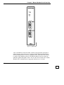
QK1402/MB User’s Guide Ref. 6299-602.9 Rev. A – 01/2003 ii General Conditions No part of this document may be copied or reproduced in any way without the previous written consent of ALTUS S.A., which reserves the right to change this manual without prior notice. In compliance with the Brazilian Consumer Protection Code, please be aware of the following issues related to personal security as well as installation in customer’s premises: The industrial automation equipment manufactured by ALTUS is robust and reliable due to a rigid quality control program. However, electronic equipment for industrial control (programmable controllers, numeric controls, etc.) can cause damage to machinery or processes controlled by them in the case of a part defect and programming or installation errors, and may even cause death. The user should analyze the possible consequences of these defects and add security safeguards to protect system security, mainly in cases of initial installation and tests when problems are more likely to happen. The user should thoroughly read the user’s guides and/or Technical Features before installation and use. ALTUS guarantees its equipment from manufacturer defects for twelve months from the date of invoice. ALTUS provides this guarantee from its manufacturing facility in São Leopoldo, RS, Brazil. The client is fully responsible for all the expenses and risks incurred on shipping products to and from that facility. This guarantee will be automatically voided if the equipment has had any modifications performed by personnel not authorized by ALTUS. The guarantee does not apply when external agents cause equipment failure, by incorrect use or installation of product, in addition to accidents and force majeur events. ALTUS guarantees its equipment functions as explicitly described in its user’s guides and/or Technical Specifications, and does not guarantee the satisfaction of any particular type of application of the equipment. ALTUS does not recognize any other guarantee, direct or implied, particularly with third party offerings. Additional information about ALTUS products, services and offerings can be requested through writing. ALTUS address can be found on the back cover of this guide. ALTUS is not responsible for non-registered information provided about its equipment. COPYRIGHT MasterTool and QUARK are registered trademarks of ALTUS Sistemas de Informática S.A. IBM is a registered trademark of International Business Machines Corporation. iii Table of Contents Table of Contents Preface xi User’s Guide Description...................................................................................................... xi Related Guides ..................................................................................................................... xi Terminology....................................................................................................................... xiii Utilized Conventions........................................................................................................... xiv Technical Support .............................................................................................................. xvi Manual Revisions .............................................................................................................. xvii Master Modbus Serial Interface 1-1 General Features................................................................................................................. 1-4 Electrical Features .............................................................................................................. 1-4 Software Features............................................................................................................... 1-5 Programming 2-1 F-1402MB.031................................................................................................................... 2-2 Introduction ................................................................................................................ 2-2 Configuration Parameters............................................................................................ 2-3 Communication Parameters......................................................................................... 2-4 Inputs and Outputs...................................................................................................... 2-5 Control Operand ......................................................................................................... 2-6 Implemented Modbus Functions.......................................................................................... 2-9 Function 01 - Read Coil Status.................................................................................. 2-10 Function 02 - Read Input Status ................................................................................ 2-11 Function 03 - Read Holding Registers........................................................................ 2-12 Function 04 - Read Input Registers............................................................................ 2-13 Function 05 - Force Single Coil................................................................................. 2-14 Function 06 - Preset Single Register .......................................................................... 2-15 Function 07 - Read Exception Status ......................................................................... 2-16 Function 08 - Diagnostics.......................................................................................... 2-17 Function 11 - Fetch Communications Event Counter.................................................. 2-18 Function 12 - Fetch Communications Event Log........................................................ 2-19 v Table of Contents Function 15 - Force Multiple Coils ............................................................................ 2-20 Function 16 - Preset Multiple Registers ..................................................................... 2-21 Function 17 - Report Slave Id.................................................................................... 2-22 Processing ........................................................................................................................ 2-23 Function Operating Sequence .................................................................................... 2-24 Function Execution Time........................................................................................... 2-26 Installation 3-1 Physical Dimensions ........................................................................................................... 3-1 Serial Interface ................................................................................................................... 3-2 RS-485 Connector....................................................................................................... 3-2 RS-232C Connector .................................................................................................... 3-2 Installation in the PC Bus ................................................................................................... 3-3 Network Communication .................................................................................................... 3-3 General Information .................................................................................................... 3-3 Point-to-Point Communication ............................................................................................ 3-5 General Information .................................................................................................... 3-5 Function Installation (software)........................................................................................... 3-5 Glossary A-1 Index B-1 vi Figures Figures Figure 1-1: QK1402/MB ......................................................................................................................... 1-2 Figure 1-2: Modbus Communication Network ......................................................................................... 1-3 Figure 2-1: F-1402MB.031 Module......................................................................................................... 2-2 Figure 2-2: Operation structure ............................................................................................................. 2-24 Figure 2-3: Module F Flowchart ............................................................................................................ 2-26 Figure 3-1: QK1402/MB dimensions....................................................................................................... 3-1 Figure 3-2: RS-485 Connection Scheme .................................................................................................. 3-4 vii Tables Tables Table 2-1: Control Operand..................................................................................................................... 2-6 Table 2-2: Function Status....................................................................................................................... 2-6 Table 2-3: Diagnostics............................................................................................................................. 2-8 Table 2-4: Parameters for Modbus Function 01 ..................................................................................... 2-10 Table 2-5: Parameters for Modbus Function 02 ..................................................................................... 2-11 Table 2-6: Parameters for Modbus Function 03 ..................................................................................... 2-12 Table 2-7: Parameters for Modbus Function 04 ..................................................................................... 2-13 Table 2-8: Parameters for Modbus Function 05 ..................................................................................... 2-14 Table 2-9: Parameters for Modbus Function 06 ..................................................................................... 2-15 Table 2-10: Parameters for Modbus Function 07 ................................................................................... 2-16 Table 2-11: Parameters for Modbus Function 08 ................................................................................... 2-17 Table 2-12: Parameters for Modbus Function 11 ................................................................................... 2-18 Table 2-13: Parameters for Modbus Function 12 ................................................................................... 2-19 Table 2-14: Parameters for Modbus Function 15 ................................................................................... 2-20 Table 2-15: Parameters for Modbus Function 16 ................................................................................... 2-21 Table 2-16: Parameters for Modbus Function 17 ................................................................................... 2-22 Table 2-17: Execution Time of F-1402MB.031 Function ....................................................................... 2-26 Table 3-1: RS-485 Connector .................................................................................................................. 3-2 Table 3-2: RS-232 Connector .................................................................................................................. 3-2 ix x Preface Preface User’s Guide Description This manual describes the Master Modbus Serial Interface for programmable controllers of the QUARK series, providing detailed information on their operation and use. This guide is organized into three chapters and one appendix, which allow finding the desired information quite easily. Chapter 1, Master Modbus Serial Interface, presents the main characteristics of the QK1402/MB communications interface and of the F-1402MB.031 function. Chapter 2, Programming, shows how to use the F-1402MB.031 module in the PC application program. Chapter 3, Installation, describes how to install the QK1402/MB interface in the PC. Appendix A, Glossary, lists the expressions and abbreviations used in this guide. Related Guides For additional information on programming software and on the Modbus protocol, refer to the the following manuals: • MasterTool Programming and User’s Guide • Technical Specifications Manual – Programmable Controllers • Modicon Modbus Protocol Reference Guide - PI-MBUS-300 xi Preface Information on the Modbus protocol can also be found on the Internet at the following web sites: • http://www.modicon.com/techpubs/toc7.html • http://www.modbus.org xii Preface Terminology The following expressions are frequently used in the text of this guide. Because of this, they need to be recognized and understood. • PC (Programmable Controller) – equipment made up of one CPU, input and output modules and power supply. • CPU (Central Processing Unit) - the main module of the PC, which processes the data. • MasterTool: ALTUS program for a standard IBM-PC® microcomputer or compatible, used in a WINDOWS® environment, which allows the development of program modules for the PCs in the PICCOLO, AL-2000, AL-3000 and QUARK series. Throughout the guide, this program will be referred to by its acronym or as "MasterTool programmer", MT4000, or MT4100. MT4000 can be used in Windows 3.1x, 95 and 98. MT4100 can be used in Windows NT or 2000. Other expressions can be found in appendix A, Glossary. xiii Preface Utilized Conventions The utilized symbols throughout this guide have the following meanings: • This mark indicates a list of items or topics. SMALL CAPS indicate names of keys, for example ENTER. is used for keys to be pressed simultaneously. For example, the simultaneous typing of the CTRL and END keys is indicated as CTRL+END. KEY1+KEY2 is used for keys to be pressed sequentially. For example, a message “Type ALT, F10” means that the ALT key should be pressed and released and then the F10 key pressed and released. KEY1, KEY2 LARGE CAPS indicate names of files and directories. Italics indicate words and characters that are typed on the keyboard or seen on the screen. For example, if you are asked to type PHOTON, these characters should be typed exactly as the appear in the guide. BOLD is used for names of commands or options, or to emphasize important parts of the text. Warning messages present the following formats and meaning: ÂDANGER: The DANGER label indicates risk of life, serious personal injury or substantial material damage will result if the necessary precautions are not taken. ªCAUTION: The CAUTION label indicates risk of life, serious personal injury or substantial material damage can result if the necessary precautions are not taken. ATTENTION: The ATTENTION label indicates that personal injury or minimal material damage can result if the necessary precautions are not taken. xiv Preface Contains important information about the product, its operation or a part of text to which special attention should be paid. xv Preface Technical Support ALTUS EXPRESS: get information by calling +55 51 589-9500 INTERNET: • Website: http://www.altus.com.br • E-mail: [email protected] If the equipment is already installed, it is advisable to have the following information available before contacting Technical Support: xvi • equipment models used and configuration of the system installed • CPU serial number, equipment revision and operating system version, shown on a fixed tag on the lateral part of the equipment. • information on the CPU mode of operation, obtained from the programming software, through the Communicates, Status, Information command. • Contents of the program modules obtained from the programming software Preface Manual Revisions Reference code, revision and date of the current user’s guide are indicated on the cover. A change in revision can mean alterations in the functional specification or user’s guide improvements. The following report lists the corresponding alterations to every revision of this guide: REVISION DATE DESCRIPTION A 11/2002 Initial revision. xvii Chapter 1 Master Modbus Serial Interface Master Modbus Serial Interface The QK1402/MB allows the user to develop applications in ladder language and to read and write in slave equipment by means of the Modbus protocol, making the QUARK line controllers (QK2000, QK800 and QK801) communications network masters. The product consists of the following modules: • QK1402/MB (hardware module) • F-1402MB.031 (software module) The QK1402/MB serial interface, when connected to the I/O bus of the PC, makes an RS-485 serial channel available, allowing the connection of the PC with a Modbus communications network, as shown in Figure 1-1. Alternatively, the RS-232C serial channel available in the QK1402/MB can be used for point-to-point connections with a Modbus slave equipment. Only one of these channels, either RS-485 or RS-232, may be used at a single time. Both cannot be used simultaneously. 1-1 Chapter 1 Master Modbus Serial Interface Figure 1-1: QK1402/MB The F-1402MB.031 function module, called by the application developed in ladder language, allows the user to configure module QK1402/MB and then develop communications with slave equipment units connected to the network by means of the Modbus protocol. The QK1402/MB can only be used with QK2000, QK800 and QK801 CPUs. For AL-2002 and AL-2003 CPU models, Modbus RTU communication is supported with the use of AL-2005 1-2 Chapter 1 Master Modbus Serial Interface coprocessor module(s) and AL-2734 Modbus Master/Slave Communications Drivers. CP QK1402/MB MODBUS MASTER MODBUS SLAVE MODBUS SLAVE Figure 1-2: Modbus Communication Network The F-1402MB.031 function module must run in QK2000, QK800 or QK801 programmable controllers, with software version 1.22 or higher. 1-3 Chapter 1 Master Modbus Serial Interface General Features • Communications interface: EIA RS-485 and RS-232 with specific RTU Modbus (master mode) protocol functions • Capacity for network communication • Activity LED indicating the module is being accessed by the PC • Transmission (TX) and reception (RX) LEDs for serial communication • Watchdog circuit • Operating temperature: 0 to 60°C, exceeding the IEC 1131 standard • Storage temperature: -25 to 70°C, accordding to IEC 1131 standard • Relative humidity: 5 to 95% (non-condensing), according to IEC 1131 standard - RH2 level • Unpacked weight: 420 g - Packed weight: 480 g • Protection class: IP 20, against incidental finger touch and without waterproof protection according to IEC 529 standard Electrical Features 1-4 • Bus power consumption: 70 mA @ 12 Vdc • Severity level of electrostatic discharge (ESD): according to IEC 1131standard, level 4 • Electrical noise immunity, oscillating wave type: according to IEC 1131 standard, severity level C, and IEEE C37.90.1 (SWC) • Immunity to irradiated electromagnetic field: 10 V/m @ 140 MHz according to IEC 1131 Chapter 1 Master Modbus Serial Interface Software Features • Uses the F-1402MB.031 function module, which implements the interface between the QK1402/MB and the PC. • Activates Modbus functions to communicate with slave equipment units over the network. • Mode of transmission: RTU, 8-bit binary code • Type of checksum: CRC-16 (cyclic redundancy check) • Implemented Modbus protocol functions: • 01 - Read Coil Status • 02 - Read Input Status • 03 - Read Holding Registers • 04 - Read Input Registers • 05 - Force Single Coil • 06 - Preset Single Register • 07 - Read Exception Status • 08 - Diagnostics • 11 - Fetch Communications Event Counter • 12 - Fetch Communications Event Log • 15 - Force Multiple Coils • 16 - Preset Multiple Registers • 17 - Report Slave Id • Configurable data rate: 38,400, 19,200, 9,600, 4,800, 2,400 or 1,200 bps • Configurable communications character parity: • No parity bit • Odd parity bit • Even parity bit • Configurable number of stop-bits: • one stop-bit • two stop-bits • Communications time-out configurable from 1 to 254 hundredths of a second 1-5 Chapter 2 Programming Programming The F-1402MB.031 function was designed to be used with the PCs in the QUARK series (QK2000, QK800 and QK801) and makes the communication interface between the PC and the QK1402/MB module. The QK1402/MB module makes the interface with the slave equipment units connected to the network. Function call and execution is carried out by the CHF instruction (function call), which must be inserted into the user’s application program, implemented in ladder language using the MasterTool programmer. 2-1 Chapter 2 Programming F-1402MB.031 CHF enable communicatio success 1402MB 031 OPER1 OPER3 OPER2 OPER4 EXEC error PROG error Figure 2-1: F-1402MB.031 Module Introduction This function must run on PCs in the QUARK series (QK2000, QK800 or QK801), with the QK1402/MB module in the bus correctly addressed (addressing straps) and declared as “QK1402” (in module C-000). The F-1402MB.031 function can be called in two distinct ways: for the configuration of the QK1402/MB and for communication with the slave equipment units on the network. The configuration call is necessary to configure the QK1402/MB serial channel. Usually only one configuration call of the F-1402MB.031 per program is necessary for each QK1402/MB module present in the bus, after power-on or after switching the PC to “execution mode”. This call must not be executed simultaneously with the communication calls, because it interferes with them. The communication call is used to perform the communication with the slave equipment units. Several calls of this type can be inserted into the application program. These calls are sequentially run when they refer to the same bus module. The F-1402MB.031 function call must not be executed from an E018 program module. 2-2 Chapter 2 Programming Configuration Parameters The CHF instruction cells used to call the function in the CONFIGURATION mode are programmed in the following manner: OPER1 – Specifies the number of parameters to be passed to the function in OPER3. This operand must be a memory constant with value 5 (KM+00005). OPER2 – Must be a memory constant operand with value 0 (KM+00000). Specifies the number of parameters allowed to be programmed in the edit window of OPER4. As this function requires no parameters in OPER4, the value of OPER2 is 0. OPER3 – Contains the parameters that are passed to the function. They are declared in an edit window when the CHF instruction is edited. The number of editable parameters is specified in OPER1- being fixed at 5 for this module: %Rxxx – Bus address where the QK1402/MB is housed. %KMxxxxx – Memory constant that defines the communication baud rate: %KM+00000 – 38,400 bps %KM+00001 – 19,200 bps %KM+00002 – 9,600 bps %KM+00003 – 4,800 bps %KM+00004 – 2,400 bps %KM+00005 – 1,200 bps %KMxxxxx - Memory constant that defines the character parity to be used in the communication: %KM+00000 – no parity %KM+00001 – odd parity %KM+00002 – even parity %KMxxxxx - Memory constant that defines the number of stop-bits of the character to be used in the communication: %KM+00001 – one stop-bit %KM+00002 – two stop-bits %KMxxxxx - Memory constant that defines the communications time-out in hundredths of a second. The values between 1 and 254 are valid for this memory constant. OPER4 – Not used . 2-3 Chapter 2 Programming Communication Parameters The CHF instruction cells used for the function call in the COMMUNICATION mode are programmed as follows: OPER1 – Specifies the number of parameters that are passed to the function in OPER3. This operand must be a memory constant with value 7 (KM+00007). OPER2 – Must be a memory constant operand with value 0 (KM+00000). Specifies the number of parameters allowed to be programmed in the edit window of OPER4. As this function requires no parameters in OPER4, the value of OPER2 is 0. OPER3 – Contains the parameters that are passed to the function. They are declared in an edit window when the CHF instruction is edited. The number of editable parameters is specified in OPER1- being fixed at 7for this module: %Rxxx - Bus address where the QK1402/MB is housed. %KMxxxxx - Memory constant that defines the address of the slave equipment to which the communication is transmitted. Values between 0 and 255 are valid (0 for broadcast messages). %KMxxxxx – Memory constant that defines the Modbus function for this communication. This memory constant may have the following values/functions: %KM+00001 - Function 01 - Read Coil Status %KM+00002 - Function 02 - Read Input Status %KM+00003 - Function 03 - Read Holding Registers %KM+00004 - Function 04 - Read Input Registers %KM+00005 - Function 05 - Force Single Coil %KM+00006 - Function 06 - Preset Single Register %KM+00007 - Function 07 - Read Exception Status %KM+00008 - Function 08 - Diagnostics %KM+00011 - Function 11 - Fetch Communications Event Counter %KM+00012 - Function 12 - Fetch Communications Event Log” %KM+00015 - Function 15 - Force Multiple Coils %KM+00016 - Function 16 - Preset Multiple Registers %KM+00017 - Function 17 - Report Slave Id %Axxx, %Exxx, %Sxxx, %Mxxxx, %TMxxx ou %KMxxxxx – First PC operand, source/destination of communication of the QK1402/MB module with the slave equipment, whose content will be copied or updated by the function. Its type depends on the function type defined by the third parameter. %KMxxxxx – Memory constant that defines the Modbus address at the first point/operand in the slave equipment. 2-4 Chapter 2 Programming %KMxxxxx – Memory constant that defines the number of slave equipment operands, and, consequently, of the master equipment, associated with this communication call %Dxxxx – Decimal operand used by the function for the internal control of its processing and for status indications of the function. A different %Dxxxx operand must be used in each different call of the function. The contents of the %Dxxxx control operand cannot be changed in any part of the application program; otherwise the function may not be correctly executed. The control operand cannot be configured as retentive in the C-000 module. OPER4 – Not used. Inputs and Outputs Description of inputs: Enable - when this input is energized the function is called, and the parameters programmed in the CHF instruction are analyzed. If the number of parameters or their type are different from the function requirements, the “Prog Error” output is activated. If they are correct, the function is ready to communicate or configure the QK1402/MB. Communicate - This input must be energized in communication calls (or configuration calls, according to the number of parameters). The function transmits the data referring to the communication (or configuration) to be executed to the QK1402/MB. The waiting period can last several scan cycles of the application program, during which no other communication is processed for this QK1402/MB module. When a valid response is received for a communication, or a valid configuration ends, the “Success” output is energized during a scan cycle of the application program. In case of failure in communication or configuration, an error output is activated during a scan cycle. The next CHF whose “enable” and “communicate” inputs are energized may then process its communication or configuration. Description of outputs: Success - It is energized during a scan cycle when the function receives a valid response from the slave equipment or when the QK1402/MB has carried out a successful configuration. The least significant byte of the control operand D returns an indicative code. Exec Error – It is energized during a scan cycle at the end of the communication processing period if the destination slave equipment does not respond to the transmitted command (time-out), or if its response contains errors, or if the QK1402/MB module is not configured or does not respond. In these cases, the least significant byte of the control operand D receives a code 2-5 Chapter 2 Programming indicating the nature of the error, and the programmed communication is not performed. This output may only be energized in communication calls. Prog Error – It is energized if there is an error in the specification of CHF operands or if there is an attempt to access non-declared operands. Control Operand The following information is stored in the D operand that controls the function: function status code, diagnostic code (error or success) or amount of data bytes expected as response from the Modbus slave, address of the slave equipment, and Modbus function number. Each one of them uses one byte and they are distributed in the D operand as follows: Byte 3 Byte 2 Byte 1 Diagnostic or Function status Amount of bytes Slave address expected at response Byte 0 Modbus function Table 2-1: Control Operand The codes valid for the function status byte are the following: Code 00 01 02 04 08 Description of the Function Status Non-initialized control operand: no call has been made to the function module yet. Inactive: the function is awaiting operation of the “communicate” input or awaiting the QK1402/MB module to be released by another CHF. Awaiting response: the function is awaiting a response from the QK1402/MB with regard to a transmission sent. Response received: the communications function has been successfully completed. Communications error: it was not possible to complete the communication function successfully. Table 2-2: Function Status 2-6 Chapter 2 Programming The Diagnostic codes, only valid for function status 01, 04 and 08, are the following: Code 00 10 11 12 13 20 21 22 23 24 25 30 31 41 42 43 44 Description of Diagnostics No indication QK1402/MB in hot swap Inactive QK1402/MB: the QK1402 module does not respond to the communications with the PC through the bus. Non-configured QK1402/MB: the module is awaiting a configuration command to configure its serial. QK1402/MB in conflict: the function that was awaiting a response from the module detected that the module’s busy status was released by another function. A module can only be used by one function at a time. This error may occur if a new configuration (module C) is sent or if another function that uses the same module was called for configuration. Module without ACK: the QK1402/MB module does not respond to the communication or configuration command. Communication time-out: the time limit for the response to arrive was reached and no response was received by the QK1402/MB in this period. Invalid response: the response received differs from the communication function sent concerning the Modbus slave equipment address. Invalid response: the response received differs from the communication function sent concerning the Modbus function number. Invalid response: the response received differs from the communication function sent concerning the amount of data bytes. Invalid response: the amount of data bytes of the response received from the QK1402/MB is higher than the available memory in the PC. Broadcast command transmitted: a function without response (broadcast) was sent. Response received: a valid response was received to the function sent. Exception response / Exception Code: 01 - Illegal Function. Exception response / Exception Code: 02 - Illegal Data Address. Exception response / Exception Code: 03 - Illegal Data Value. Exception response / Exception Code: 04 - Slave Equipment Failure. 2-7 Chapter 2 Programming 45 46 47 48 49 to 4F Exception response / Exception Code: 05 - Acknowledge. Exception response / Exception Code: 06 - Slave Equipment Busy. Exception response / Exception Code: 07 - Negative Acknowledge. Exception response / Exception Code: 08 - Memory Parity Error. Exception responses: the least significant nibble of this byte indicates the Exception Code returned by the slave equipment. Available for future use. Table 2-3: Diagnostics For diagnostics 00 none of the function outputs is activated. For diagnostics 30 and 31 the Success output is activated. For the other diagnostics, the EXEC Error is activated. The address bytes of the slave equipment address and the bytes of the Modbus function number are for exclusive use and internal control of the communication function. 2-8 Chapter 2 Programming Implemented Modbus Functions The Modbus protocol, created by Gould Modicon, defines a series of functions for reading status and values, and for writing status and values, and for testing the communication network and slave equipment. Reading and writing operations use continuous (sequential) operand ranges. The following is a description of each of the functions implemented in the F-1402MB.031 function with their respective parameters and limits for their calls. 2-9 Chapter 2 Programming Function 01 - Read Coil Status Allows the user to read the logical status (on/off) of output control relays (coils) from the addressed slave equipment. Does not support broadcast communication. Parameter %Rxxx %KMxxxxx %KM+00001 %Axxx.x %Exxx.x %Sxxx.x %KMxxxxx %KMxxxxx %Dxxxx Description Bus address where the QK1402/MB card is housed Address of the slave equipment to which communication is transmitted Range: 1 ≤ address ≤ 255 Type of Modbus function of this communication First subdivision of PC operand from which PC operands will be updated Modbus address of first point in the slave equipment to be read The relays are numbered from address 0 (this corresponds to the coil number 1, according to Modbus standard). Number of points of the slave equipment to be read Range: 1 ≤ number of points ≤ 240 Address of decimal operand used by the function for the internal control of its processing and for function status indications Table 2-4: Parameters for Modbus Function 01 2-10 Chapter 2 Programming Function 02 - Read Input Status Allows the user to read the logic status (on/off) of input status from the addressed slave equipment. This function does not support broadcast communication. Parameter %Rxxx %KMxxxxx %KM+00002 %Axxx.x %Exxx.x %Sxxx.x %KMxxxxx %KMxxxxx %Dxxxx Description Bus address where the QK1402/MB card is housed Address of the slave equipment to which communication is transmitted. Range: 1 ≤ address ≤ 255 Type of Modbus function of this communication First subdivision of PC operand from which PC operands will be updated Modbus address of first point in the slave equipment to be read. The inputs are numbered from address 0 (this corresponds to the input status number 10001, according to Modbus standard). Number of points of the slave equipment whose contents will be read Range: 1 ≤ number of points ≤ 240 Address of decimal operand used by the function for the internal control of its processing and for function status indications Table 2-5: Parameters for Modbus Function 02 2-11 Chapter 2 Programming Function 03 - Read Holding Registers Allows the user to read 16-bit holding registers from the addressed slave equipment. This function does not support broadcast communication. Parameter %Rxxx %KMxxxxx %KM+00003 %Mxxxx %TMxxx %KMxxxxx %KMxxxxx %Dxxxx Description Bus address where the QK1402/MB card is housed Address of the slave equipment to which communication is transmitted. Range: 1 ≤ address ≤ 255 Type of Modbus function of this communication First memory operand of the PC whose contents will be updated by the function or identification of the table that will be updated from its “0” position Modbus address of the first holding register in the slave equipment to be read. The registers are numbered from address 0 (this corresponds to the holding register number 40001 according to MODBUS standard). Number of registers of the slave equipment to be read Range: 1 ≤ number of registers ≤ 64 Address of decimal operand used by the function for the internal control of its processing and for function status indications Table 2-6: Parameters for Modbus Function 03 2-12 Chapter 2 Programming Function 04 - Read Input Registers Allows the user to read 16-bit input registers from the addressed slave equipment. This function does not support broadcast communication. Parameter %Rxxx %KMxxxxx %KM+00004 %Mxxxx %TMxxx %KMxxxxx %KMxxxxx %Dxxxx Description Bus address where the QK1402/MB card is housed Address of the slave equipment to which communication is transmitted. Range: 1 ≤ address ≤ 255 Type of Modbus function of this communication First memory operand of the PC that will be updated by the function or identification of the table that will be updated from its “0” position Modbus address of the first input register in the slave equipment to be read. The input registers are numbered from address 0 (this corresponds to the input register number 30001 according to MODBUS standard). Number of registers of the slave equipment whose contents will be read Range: 1 ≤ number of registers ≤ 64 Address of decimal operand used by the function for the internal control of its processing and for function status indications Table 2-7: Parameters for Modbus Function 04 2-13 Chapter 2 Programming Function 05 - Force Single Coil Allows the user to write the logical status (on/off) of an output control relay (coil) in the addressed slave equipment or in all network slaves by means of a broadcast message (address 00). Parameter %Rxxx %KMxxxxx %KM+00005 %Axxx.x %Exxx.x %Sxxx.x %KMxxxxx %KMxxxxx %Dxxxx Description Bus address where the QK1402/MB card is housed Address of the slave equipment to which communication is transmitted Range: 0 ≤ address ≤ 255 Type of Modbus function of this communication First subdivision of PC operand whose contents will be used by the function. Modbus address of the point in the slave equipment to be written. The coils are numbered from address 0 (this corresponds to the coil number 1 according to MODBUS standard). Not used Address of decimal operand used by the function for the internal control of its processing and for function status indications Table 2-8: Parameters for Modbus Function 05 2-14 Chapter 2 Programming Function 06 - Preset Single Register Allows the user to write a 16-bit holding register in the addressed slave equipment or in all the network slaves by means of a broadcast message (address 00). Parameter %Rxxx %KMxxxxx %KM+00006 %Mxxxx %TMxxx %KMxxxxx %KMxxxxx %Dxxxx Description Bus address where the QK1402/MB card is housed Address of the slave equipment to which communication is transmitted Range: 0 ≤ address ≤ 255 Type of Modbus function of this communication Memory operand of the PC that will be used by the function or memory table whose position 0 will be used Modbus address of holding register in the slave equipment to be modified. The registers are numbered from address 0 (this corresponds to the holding register number 40001 according to MODBUS standard). Not used Address of decimal operand used by the function for the internal control of its processing and for function status indications Table 2-9: Parameters for Modbus Function 06 2-15 Chapter 2 Programming Function 07 - Read Exception Status Allows the user to read the logical status (on/off) of the 8 status control relays previously defined by the addressed slave equipment. This function does not support broadcast communication. Parameter %Rxxx %KMxxxxx %KM+00007 %Axxx.0 %Exxx.0 %Sxxx.0 %KMxxxxx %KMxxxxx %Dxxxx Description Bus address where the QK1402/MB card is housed Address of the slave equipment to which communication is transmitted Range: 1 ≤ address ≤ 255 Type of Modbus function of this communication First subdivision of PC operand whose contents will be updated by the function (It is mandatory to use the operand from bit 0.) Not used Not used Address of decimal operand used by the function for the internal control of its processing and for function status indications Table 2-10: Parameters for Modbus Function 07 2-16 Chapter 2 Programming Function 08 - Diagnostics Allows the user to test the communication system or error conditions that are present in the slave equipment according to the code and data for diagnostics. This, however, does not affect the operation of the slave equipment. This function does not support broadcast communication. Parameter %Rxxx %KMxxxxx %KM+00008 %Mxxxx %TMxxx %KMxxxxx %KMxxxxx %Dxxxx Description Bus address where the QK1402/MB card is housed Address of the slave equipment to which communication is transmitted Range: 1 ≤ address ≤ 255 Type of Modbus function of this communication Memory operand of the PC whose contents will be updated by the function or identification of the memory table whose position 0 will be updated with the data field of the response from the slave equipment Diagnostics subfunction (Check slave equipment user’s guide.) Data associated with the diagnostics subfunction when necessary (Check slave equipment user’s guide.) Address of decimal operand used by the function for the internal control of its processing and for function status indications Table 2-11: Parameters for Modbus Function 08 2-17 Chapter 2 Programming Function 11 - Fetch Communications Event Counter Allows the user to read status information and the event counter from the slave equipment. This function does not support broadcast communication. Parameter %Rxxx %KMxxxxx %KM+00011 %Mxxxx %TMxxx %KMxxxxx %KMxxxxx %Dxxxx Description Bus address where the QK1402/MB card is housed Address of the slave equipment to which communication is transmitted Range: 1 ≤ address ≤ 255 Type of Modbus function of this communication Address of the first memory operand or memory table (initial position = 0) to which the values returned by the function will be transferred Not used Not used Address of decimal operand used by the function for the internal control of its processing and for function status indications Table 2-12: Parameters for Modbus Function 11 The normal response to this function consists of one status word and an event counter occupying, therefore, two memory positions in the PC. 2-18 Chapter 2 Programming Function 12 - Fetch Communications Event Log Allows the user to read status information from the device, event counter, message counter, and receive a list of communication events from the slave equipment. This function does not support broadcast communication. Parameter %Rxxx %KMxxxxx %KM+00012 %Mxxxx %TMxxx %KMxxxxx %KMxxxxx %Dxxxx Description Bus address where the QK1402/MB card is housed Address of the slave equipment to which communication is transmitted Range: 1 ≤ address ≤ 255 Type of Modbus function of this communication First memory operand of the PC whose contents will be updated by the function or identification of the table that will be updated from its 0 position. Not used Not used Address of decimal operand used by the function for the internal control of its processing and for function status indications Table 2-13: Parameters for Modbus Function 12 The number of necessary memory positions to receive the values returned by this function may vary from 3 to 35, according to the configuration of the slave equipment. See the slave equipment user’s guide and the “Modicon Modbus Protocol Reference Guide”. Event 0 of the slave equipment will be transferred to the highest byte of the PC first associated memory position. Event 1 of the slave equipment will be transferred to the lowest byte of the PC first associated memory position. Event 3 of the slave equipment will be transferred to the highest byte of the PC second associated memory position. This is the sequence adopted for the transfer of all events received. 2-19 Chapter 2 Programming Function 15 - Force Multiple Coils Allows the user to force the logical status (on/off) of output control relays (coils) in the addressed slave equipment or in all network slaves by means of a broadcast message (address 00). Parameter %Rxxx %KMxxxxx %KM+00015 %Axxx.x %Exxx.x %Sxxx.x %KMxxxxx %KMxxxxx %Dxxxx Description Bus address where the QK1402/MB card is housed Address of the slave equipment to which communication is transmitted Range: 0 ≤ address ≤ 255 Type of Modbus function of this communication First subdivision of PC operand whose contents will be used by the function Modbus address of the first point in the slave equipment to be written. The coils are numbered from address 0 (this corresponds to the coil number 1 according to MODBUS standard). Number of points of the slave equipment whose contents will be written. Range: 1 ≤ points ≤ 240 Address of decimal operand used by the function for the internal control of its processing and for function status indications Table 2-14: Parameters for Modbus Function 15 2-20 Chapter 2 Programming Function 16 - Preset Multiple Registers Allows the user to write on 16-bit holding registers, of the addressed slave equipment, or of all network slaves by means of a broadcast message (address 00). Parameter %Rxxx %KMxxxxx %KM+00016 %Mxxxx %TMxxx %KMxxxxx %KMxxxxx %Dxxxx Description Bus address where the QK1402/MB card is housed Address of the slave equipment to which communication is transmitted Range: 0 ≤ address ≤ 255 Type of Modbus function of this communication Address of the first memory operand or memory table (initial position = 0) that will be used by this function Modbus address of the first holding register in the slave equipment to be modified. The holding registers are numbered from address 0 (this corresponds to the holding register number 40001 according to MODBUS standard). Number of registers of the slave equipment whose contents will be modified. Range: 1 ≤ number of registers ≤ 64 Address of decimal operand used by the function for the internal control of its processing and for function status indications Table 2-15: Parameters for Modbus Function 16 2-21 Chapter 2 Programming Function 17 - Report Slave Id Allows the user to read the information on the type of slave and supplementary data from the slave equipment. (Check the user’s guide of the respective equipment). This function does not support broadcast communication. Parameter %Rxxx %KMxxxxx %KM+00017 %Mxxxx %TMxxx %KMxxxxx %KMxxxxx %Dxxxx Description Bus address where the QK1402/MB card is housed Address of the slave equipment to which communication is transmitted Range: 1 ≤ address ≤ 255 Type of Modbus function of this communication Address of the first memory operand or memory table (initial position = 0) to which the values returned by the function will be transferred. Not used Not used Address of decimal operand used by the function for the internal control of its processing and for function status indications Table 2-16: Parameters for Modbus Function 17 The number of memory positions necessary to receive the values returned by this function may vary from two positions up to a limit defined by the configuration of the slave equipment. Check the slave equipment user’s guide and the “Modicon Modbus Protocol Reference Guide”. Data byte 0 (Slave Id) of the response from the slave equipment will be transferred to the highest byte of the PC first associated memory position. Data byte 1 (Run Indicator Status) will be transferred to the lowest byte of the PC first associated memory position. Data byte 3 (if applicable) will be transferred to the highest byte of the PC second associated memory position. This sequence is adopted for the transfer of all received data. 2-22 Chapter 2 Programming Processing When an application program is running in the PC, at most one call (CHF instruction) of the F-1402MB.031 function per QK1402/MB module may be active, even if there are several calls whose “enable” and/or “communication” inputs are active. After the function called has been executed, some of their outputs may be kept energized during one scan cycle of the application program. In the following scan cycle the function will release the outputs and release the QK1402/MB module for the next CHF (function call), which could be awaiting the module to be released in order to switch to the active condition. The application program cannot skip or disable the function call instruction while it is active. We recommend keeping the “enable” input of the communication calls permanently active. This way, the control will be made only by the “communicate” input. The “communicate” input does not have to be continuously active until the end of the communication. It only has to be activated once (by a scan cycle) to enable the communication, provided there is no other CHF using the same QK1402/MB module in this cycle. A possible approach to initiate a communication and realize it has ended is described below: • keep the “enable” input always active • when the communication must be initiated, activate the “communication” input • when some of the outputs (success or error) goes to active state, the communication has ended, and the “communication” input may be turned off. Also, the %Dxxxx operand may be examined to have details about possible errors. The main processes carried out by the F-1402MB.031 function are the following: • consistency of function call parameters; • verification of the QK1402/MB module status in the bus; • verification of configuration calls of the QK1402/MB module; • verification of “inactive” status when the module is released, so that communication commands can be sent; 2-23 Chapter 2 Programming • verification of “awaiting response” status when the module is busy with the function itself, for obtaining responses from the module or keeping a timeout count; • consistency of the communication function to be executed; • consistency of the response received and transfer of response to memory operands or memory tables; • updating of function status and outputs Whenever it is necessary to establish short communications with the slave equipment, it is possible to always keep the “communicate” inputs of the various function calls active for different Modbus functions and different slaves. This situation determines that, as soon as a function call is over, the next call be immediately carried out, and so forth. PC BUS BARRAMENTO CP CPU UCP QK1402/MB INPUTS ENTRADAS EXECUTION EXECUTIVO EXECUTES EXECUTA QK1402/MB E001E001 CHF F-1402MB.031 OUTPUTS 00111351B SAÍDAS SERIAL INTERFACE SERIAL INTERFACE Figure 2-2: Operation structure Function Operating Sequence A communications operation follows these steps: 2-24 Chapter 2 Programming • Scan Cycle #1: As the “enable” and “communicate” input are activated, the data related to the communication to be established (address of slave equipment, Modbus function, Modbus address, etc) are passed to the QK1402/MB module. The function terminates execution and returns to the user’s ladder application. The QK1402/MB module produces the configured Modbus command and transmits it. • Scan Cycle #2 to #n – Awaiting response from slave equipment: The function consults the operating status, which is updated (Situation “A” in the “Execution Time of F-1402MB.031 Function” table). During the cycles subsequent to the initial one (#1), the QK1402/MB ends the serial transmission and awaits the response from the addressed slave equipment. In this situation, the “awaiting response” status is successively returned to the CPU. The QK1402 keeps awaiting the response from the slave or signals the completion of the operation due to time-out or other errors, by indication of the respective error code to the CPU. The number of scan cycles performed by the CPU in this condition depends on the response time from the slave equipment or the time-out configured for the function. In this situation, the function execution time corresponds to item “A” in table 217 – Execution Time of F-1402MB.031 Function. • Scan Cycle #n+1: Once the previous step has been accomplished, the data are transferred to PC operands and the final status of the function is indicated (“Success Code,” “Returned Exception Code,” “Time-out,” etc...). The appropriate function output remains active during this scan (“Success” or “Exec Error”). • Scan Cycle #n+2: The function output (“Success” or “Exec Error”) returns to its normal condition. 2-25 Chapter 2 Programming INOPERATIVE COMMUNIC. Y OFF EXIT SERIAL COMMAND SLAVE RESPONSE Y SUCCESS UPDATES STATUS Y EXCEEDED TIME COMMUNICATION ERROR Figure 2-3: Module F Flowchart Function Execution Time In different situations, the following execution times for the F-1402MB.031 function calls are observed: Situation A) No activity (just enablement) B) Communicate input activated C) Reading 1 register D) Reading 60 registers E) Writing 60 registers Function call execution time 860 µs 2.2 ms 2.8 ms 24 ms 25 ms Table 2-17: Execution Time of F-1402MB.031 Function 2-26 Chapter 2 Programming For example, the execution time above associated with a “Reading 60 registers” situation is considered the necessary time for sixty 16-bit registers to be transferred from the QK1402/MB to the PC operands, after the response from the slave equipment has been correctly received and decoded. The time periods above only consider the data transfer between CPU operands and the QK1402/MB module. Delays associated with the serial transmission, slave equipment response time and programmable controller scan cycle are not included. 2-27 Chapter 3 Installation Installation This chapter presents the QK1402/MB Master Modbus Serial Interface installation procedures. Physical Dimensions The QK1402/MB dimensions are presented in the figure below. Figure 3-1: QK1402/MB dimensions 3-1 Chapter 3 Installation Serial Interface The QK1402/MB has two 9-pin female connectors, one complies with the RS-232C standard, and the other one follows the RS-485 standard, as identified on the module panel. The following tables show the pinout of each connector. The RS-232 and RS-485 serial interfaces of the QK1402/MB module cannot be used simultaneously. RS-485 Connector PIN 1 2 3 4 5 6 7 8 9 SIGNAL PGND NC TXD/RXD+ NC SGND BREF+ TXD/RXDTXD/RXDTXD/RXD- Table 3-1: RS-485 Connector RS-232C Connector PIN 1 2 3 4 5 6 7 8 9 SIGNAL PGND TX RX RTS CTS DSR SGND NC DTR Table 3-2: RS-232 Connector The RTS, CTS, DSR and DTR pins, although present, are not actually used by the QK1402/MB. 3-2 Chapter 3 Installation Installation in the PC Bus The installation of the QK1402 interface is made on the mounting rail (QK1500) along with the PC CPU or QK2512 power supply and the other I/O modules. The module has a slot at the rear which allows inserting it in the rail in the electrical cabinet. For further information on how to insert and remove the module from the rail, check the QUARK CPUs User’s Guide. Before inserting the module in the rail, the address in the PC bus must be defined by means of the existing jumpers (S1), which can be accessed through a lateral opening on the box. The module address must be the same one configured in the application program through MASTERTOOL or AL-3830 Programmers in their bus declaration – see Programmer User’s Guide. After defining the address, the module is inserted into the bus and connected to the communications cable with the CPU (flat cable: QK1304, QK1308, QK1312 or QK1316). For further information on the module address and connection to the bus, check the QK2000/MSP CPU user’s guide. It is possible to use more than one QK1402/MB module in a single CPU bus, provided they are properly configured and programmed (ladder program) and have an independent Modbus communication (two RS-485 networks, for example). Network Communication General Information The installation of a communication network must comply with the RS-485 standard according to the following figure. For example, the items below, which can be ordered from ALTUS, may be used. • AL-2305: Branch Cable (CMDB9 - RS485) • AL-2600: Branch and Network Termination Module • AL-2301: RS-485 Network Cable The switches of the AL-2600 branch/termination module in the extreme nodes of the RS-485 network must be configured as “Profibus terminations”, and those AL-2600 in intermediate nodes must be configured as “branches”. 3-3 Chapter 3 Installation Note that the QK1402/MB is usually connected to one of the RS-485 network ends, a situation in which one of the AL-2301 cables from Figure 3-2 wouldn’t exist and the AL-2600 would be configured as Profibus termination instead of as branch. Also, note that just one of the AL-2600 must be connected to the ground (GND terminal connected to the “earth ground” on the panel). Conector DB-9 RS-485 SGND BREF+ TXD/RXDTXD/RXD+ (5) (6) (8) (3) AL-2305 QK1402/MB 0 1 2 3 4 5 SHD D+ D- BR+ BR-GND AL-2600 SHD D+ D- BR+ BR- 0 1 2 3 4 SHD D+ D- BR+ BR- 0 1 2 AL-2301 4 AL-2301 Figure 3-2: RS-485 Connection Scheme 3-4 3 Chapter 3 Installation Point-to-Point Communication General Information The point-to-point communication between the QK1402/MB and a Modbus slave equipment sometimes can be made through an RS-232 standard communication port. The identification of the pins of the QK1402/MB RS-232 (DTE) communication port is presented in table 3-2. The configuration of the cable to be used will depend on the pinout of the connector available in the slave equipment. The following cables, supplied by ALTUS, can be used in some situations. • AL-1344: CMDB25-CMDB9 (Modem/PC) cable, for the connection of the QK1402/MB to modem equipment with an EIA RS-232C standard connector; • AL-1342: CMDB9-CFDB9 (IBM PC /PC) cable, for the connection to IBM-PC equipment that emulates modem signals, with DB9 connector; • AL-1366: CMDB9-CMDB9 cable, for the connection to other ALTUS equipment with a 9-pin RS-232C standard interface; • AL-1383: CMDB9-CFDB25 cable for the connection to IBM-PC equipment with DB25 connector; • AL-1390: CMDB9-CFDB9 cable, for the connection to IBM-PC equipment, with DB9 connector; Function Installation (software) The floppy disk that comes with the product contains all the functions (modules F) for the supported CPU models. The F-1402MB.031 function file, according to the CPU type, must be copied to the application directory (ladder) and inserted into the project through a MasterTool programmer (Project, Edit, Insert Module option). The F-1402MB.031 function must be called from the CHF instruction. 3-5 Appendix A Glossary Glossary This appendix presents a glossary of words and abbreviations frequently used in this guide. • ALTUS Ladder language: Set of instructions and operands that allow editing an application program to be used in a PC • Application Program: Control algorithm, usually programmed in ladder language, which specifies the control of a specific machine by the PC • Baud Rate (Transmission Rate): Rate at which information bits are transmitted through a serial interface or communications network • Bit: Basic information unit, which has two states: 0 or 1 • Byte: information unit consisting of eight bits • Command: Instruction typed by the user indicating to the equipment or program which task is to be executed • Communications Network: Set of devices (nodes) interconnected by communications channels • Configuration: Preparation to get a product working by means of the integration of hardware and software • Configuration Module (Module C): Single module in a PC program that contains several parameters that are necessary for the controller to operate, such as the amount of operands and the I/O module disposition in the bus • Connector: mechanical element that allows connecting or separating two or more components or electrical circuits • CPU: Central Processing Unit – Controls information flow, interprets and executes the program instructions and monitors the system devices. • Debugging: Tests to determine the correct way a product works, and to spot and correct errors A-1 Appendix A Glossary A-2 • Default: preset value for a variable used in case there is no redefinition • Diagnostic: Procedure used to detect and isolate flaws – It is also the group of data used for such determination, which can be used to analyze and correct problems. • Execution Modules (Module E): Modules that contain the application program – They can be of three types: E000, E001 and E018. Module E000 is executed one single time when the PC is energized or in the switch from programming to execution mode. Module E001 contains the main segment of the program that runs cyclically, while module E018 is activated by time interruption. • Executive Program: Operating system of a programmable controller – It controls the basic controller functions and the execution of application programs. • Executive Software: A PC operating system. It controls the basic functions of the programmable controller and the execution of application programs • Frame: Information unit transmitted over the network • Function Module (Modulo F): Module of a PC program that is called by the main module (module E) or by another function module or procedure, with transfer of parameters and return of values, working as a sub-routine • Hardware: Physical devices used in data processing, where programs (software) are normally run • I/O Module: Module belonging to the I/O subsystem • Instruction: Operation to be executed on a group of operands in a program • Interface: Device that adapts the transfer of signals between two devices electrically and/or logically. • Interruption: Priority event that temporarily suspends the execution of a program – The interruptions can be divided into two generic types: hardware and software. The former is caused by a signal coming from a peripheral device, and the latter is created by instructions in a program. • Kbytes: Representative unit of memory– It represents 1,024 bytes. • Logic: Graphic matrix where the relay diagram language instructions that compose an application program are inserted – a set of logical items sequentially ordered constitutes a program module • Master: Equipment of a communications network from which command requests are originated and passed to other devices on the network Appendix A Glossary • Master-slave communications network: Communications network where the data transfers are only initiated from one single node (the network master) connected to the data bus – The other network nodes (slaves) only respond when requested. • Menu: Set of available options to be selected by the user in order to activate or execute a certain task – These options are displayed on a screen by a program. • Module (when referring to hardware): Basic element of a complete system that has well-defined functions – It is normally connected to the system by connectors. It can be easily replaced. • Module (when referring to software): Part of an application program capable of doing a specific function – It can run independently or in conjunction with other modules exchanging information by means of parameter transfer. • Multimaster communications network: Communications network where information transfers are initiated by any node connected to the data bus • Nibble: Information unit consisting of four bits • Node: Any station of a network with communication capability using an established protocol • Octet: Group of eight bits numbered from 0 to 7 • Operands: Elements on which instructions act – They can represent constants, variables or variable sets. • PC: Abbreviation of Programmable Controller • Procedure Module (Module P): Module of a PC program that is called from the main module (module E) or from another procedure module or function, without parameter transfer • Program: Set of basic instructions properly ordered with which someone instructs a certain machine for it to perform operations with the data in order to obtain a result • Programmable controller: Device that performs control under the command of an application program written in relay and block language – It consists of a CPU, a power source, and an I/O structure. • Programming: The act of preparing all the steps of a program for a computer or similar device • Programming language: A set of rules, conventions and syntax used to elaborate a program – a set of symbols used to represent and communicate information or data among people and machines A-3 Appendix A Glossary A-4 • Programming logic: Graphic matrix where the relay diagram language instructions that compose an application program are inserted – a set of logical items sequentially ordered constitutes a program module • Programming terminal: Personal Computer running a PC programming software such as AL-3830, AL-3832 or MasterTool • Protocol: Procedure rules and conventional formats that, by means of control signals, allow the establishment of data transmission and error retrieval among devices • Remote station: Devices that read and write input and output points of the controlled process, communicating their value when the CPU is active • RS-485/EIA-485: Industrial standard (physical level) for data communication – Its main characteristics are the following: communication possibility with several modes and high immunity to electromagnetic interference due to their operation with differential voltage. • Scan cycle: A complete execution of a programmable controller executive program • Serial: Set of modules that have the same AL, QK, FT or PL code and the same initial numeric character – For instance, the AL 2000 serial comprises the AL-2000/MSP-C and AL-2002/MSP controllers. • Serial channel: Device which allows the connection and communication of data between two or among more devices through a common standard • Slave: Device of a communications network that responds to command requests originated from the master • Software: Computer programs, procedure and rules related to a data processing systems operation • Status: Module status • Supervision status: Equipment connected to a PC network or instrumentation whose purpose is to monitor or control variables of a process • System: Set of devices used for the control of a machine or process, consisting of the PC CPU, I/O module, Personal Computer and H/M interfaces. • Tag: Name associated to an operand or logic that allows a summarized identification of its content • Time-out: maximum preset time for a communication to be completed, causing a communications error if exceeded • Word: Unit of information composed of sixteen bits. Appendix A Glossary A-5 Appendix I Alphabetical Index Index —C— —I— Communication Parameters, 4 Communication Network, 3 Point-to-Point, 6 Configuration Parameters, 3 Control Operand, 6 Inputs and Outputs, 5 Communicate, 5 Enable, 5 Exec Error, 6 Prog Error, 6 Success, 5 Installation, 1 Installation Bus, 3 Function, 6 —D— Diagnostics Codes, 9 —E— E018, 2 Execution Time, 27 —F— F-1402MB.031, 2 Features, 4 Electrical Features, 4 General Features, 4 Software Features, 5 Function Installation, 6 Function Execution Time, 27 Operating Sequence, 26 Processing, 24 —M— Modbus Function 04 - Read Input Registers, 14 Modbus Function 01 - Read Coil Status, 11 02 - Read Input Status, 12 03 - Read Holding Registers, 13 05 - Force Single Coil, 15 06 - Preset Single Register, 16 07 - Read Exception Status, 17 08 - Diagnostics, 18 11 - Fetch Communications Event Counter, 19 12 - Fetch Communications Event Log, 20 15 - Force Multiple Coils, 21 16 - Preset Multiple Registers, 22 17 - Report Slave Id, 23 Modbus Functions, 10 —P— Physical Dimensions, 1 Programming, 1 I-1 Alphabetical Index Appendix I —S— Serial Interface Connector RS-232, 2 Serial Interface, 2 I-2 Serial Interface Connector RS-485, 2 Status Codes, 6