1
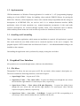
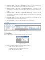
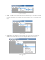
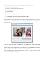
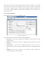
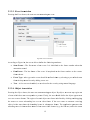
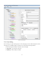
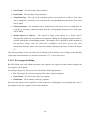
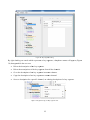
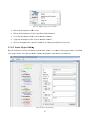
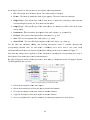
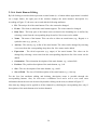
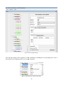
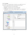
Video Content Analysis Tool: 3DVideoAnnotator Graphical User Interface for annotating video sequences Version 2.4 1 Table of Contents 1. Features .......................................................................................................................................... 3 1.1. Introduction ............................................................................................................................. 3 1.2. Implementation........................................................................................................................ 4 1.3. Installing and Uninstalling ...................................................................................................... 4 2. Graphical User Interface ................................................................................................................ 4 2.1. File Menu ................................................................................................................................ 4 2.2. View Menu .............................................................................................................................. 5 2.3. Windows Menu ....................................................................................................................... 7 2.3.1. Player ............................................................................................................................... 7 2.3.2. Annotator ......................................................................................................................... 9 2.3.2.1. Shot Annotation ...................................................................................................... 10 2.3.2.2. Key Segment Annotation........................................................................................ 11 2.3.2.3. Event Annotation .................................................................................................... 12 2.3.2.4. Object Annotation................................................................................................... 12 2.3.2.5. Human Annotation ................................................................................................. 14 2.3.3. Timeline ......................................................................................................................... 17 2.3.4. Editor.............................................................................................................................. 20 2.3.4.1. Shot Editing ............................................................................................................ 21 2.3.4.2. Transition Editing ................................................................................................... 23 2.3.4.3. Key Segment Editing .............................................................................................. 24 2.3.4.4. Event Editing .......................................................................................................... 26 2.3.4.5. Static Object Editing............................................................................................... 27 2.3.4.6. Static Human Editing.............................................................................................. 29 2.3.4.7. Moving Object Editing ........................................................................................... 31 2.3.4.8. Moving Human Editing .......................................................................................... 33 2.3.4.9. Cut Editing.............................................................................................................. 36 2.3.4.10. Header Editing ........................................................................................................ 37 2.3.5. Analyzer ......................................................................................................................... 38 2.3.5.1. Shot Boundary Detector’s Manual ......................................................................... 40 2.3.5.2. Haarcascade frontal face detector manual .............................................................. 40 2.3.5.3. Color+Haarcascade Frontal Face Detector’s Manual ............................................. 41 2.3.5.4. Frontal–Profile Face Detector’s Manual ................................................................ 42 2.3.5.5. Object Detector’s Manual ....................................................................................... 43 2.3.5.6. Particles Tracker’s Manual ..................................................................................... 44 2.3.5.7. LSK Stereo Tracker’s Manual ................................................................................ 45 2.3.5.8. LSK Tracker’s Manual ........................................................................................... 46 2.3.5.9. 3D Rules Detector’s Manual .................................................................................. 47 2.3.5.10. UFO Detector’s Manual ......................................................................................... 48 2.3.5.11. Keyframe Selection Tool’s Manual ........................................................................ 49 2 1. Feattures 1.1. Introoduction 3DVideoAnnnotator is an application that asssists users in n the task of o annotatinng video seq quences andd viewing thee corresponnding resultts. A video sequence can c be a sin ngle-view vvideo or a stereoscopic s c video consiisting of tw wo channelss (left and rright) and their t corressponding diisparity chaannels. Eachh video can bbe annotateed with shott descriptionns, key seg gment descrriptions, eveent descripttions, objecct and humann (either stattic or moving) descripptions, eitheer manually or automattic through algorithmss. Users can nnavigate thee descriptions through user friend dly modules such as tim melines and d a tree view w representatiion, and eddit them. Th he applicatioon also allo ows the annotated descr criptions to be stored inn an output A AVDP/XML L file and can c read exxisting desccriptions fro om an AVD DP/XML file. Figure 1 displays thee application. Figure 1: 3D DVideoAnnotato or application. 3 1.2. Implementation 3DVideoAnnotator is a Windows Forms Application. It is coded in C++/CLI programming language making use of the OPENCV library for handling videos and the XERCES library for parsing the XML files. Libraries, which implement various video content analysis algorithms and the storage of descriptions in AVDP/XML files, are used as well. It is a multiple-document interface (MDI) application, where all main operations (e.g., manual annotation, navigation of video and audio content’s descriptions) are executed through separate forms. GUI components such as buttons, sliders and drop-down menus are used in order to provide user friendliness and ease of use. 1.3. Installing and Uninstalling This is a stand-alone application, which means no installation is required. All application’s required files reside inside the root folder which can be extracted anywhere in the user’s computer. The program requires .NET Framework 4 and Microsoft Visual C++ 2010 Redistributable Package to be installed on the computer. Uninstalling the application can be performed by simply erasing the root folder. 2. Graphical User Interface All operations are executed through menus, which are described below. 2.1. File Menu Through the File Menu, the user can open an AVI file, save/load a video content’s description, etc.. The menu contains the following functions, as shown in Figure 2. Open Single Video – It opens an AVI file. Open Stereo Video → Two videos (L/R) – It opens two dialog boxes though the user selects the left and the right channel of a stereoscopic video, respectively. Open Stereo Video → Four videos (L/R plus Disparity) – It opens four dialog boxes though the user selects the left and the right channel of a stereoscopic video and the respective disparity channels, respectively. Open Stereo Video → One video → Left-Right – It opens an AVI file corresponding to a stereoscopic video which contains the two channels side-by-side. 4 V → One video → Top-Botttom – It opeens an AVI file corresp ponding to a Opeen Stereo Video stereoscopic viideo which contains c thee two chann nels in a top-bottom maanner. V → One O video → Left-Right plus Disparity D – It opens an a AVI filee Opeen Stereo Video corrresponding to a stereosscopic videeo which co ontains the color c and ddisparity channels sideby-sside. Opeen Stereo Video V → One O video → Top-Bottom plus Disparity – It opens an AVI filee corrresponding to a stereosscopic videoo which con ntains the color and dissparity two channels inn a top-bottom manner. m Reaad XML (A AVDP) – It loads a viddeo content’s descriptio on from an AVDP/XM ML file. Thee loadded descripttion is added to the exi sting descriiption. Savve XML (AV VDP) – It saves s the viddeo annotattions as an AVDP/XML A L file. Exitt Figgure 2: File meenu. 2.2. View w Menu The View M Menu (Figurre 3) is asso ociated withh the video viewing. v Specifically: Figgure 3: View Menu. Playy – It includdes the follo owing threee playback modes m (Figu ure 4): o Slow – Play the vid deo in slow w mode. o Normaal – Play thee video accoording to itss frame rate.. o Fast – Play P the vid deo in fast m mode. 5 Figurre 4: Playback modes. m i Figure 5.. Note that it i is possiblee Zooom – It incluudes seven available zooom factorss as shown in for some zoom m factors to be disabledd, if the scrreen resolution is low or if the frrame size iss largge. Fiigure 5: Zoomin ng. ut video is a stereoscop pic video, the user can sselect which h of the Sterreo Mode – If the inpu channnels will be b visible in n the Player Window th hrough the modes m show wn in Figure 6. Figuure 6: Stereo Modes. 6 2.3. Win ndows Me enu The Windows Menu (F Figure 7) is the most im mportant on ne since all main operaations (videeo playbackk, video conteent’s descripption annotaation, editinng and navig gation) are initiated i herre. Figurre 7: Windows Menu. M Each of thee five windoows is descrribed next. 2.3.1. Pla ayer The Playerr Window oppens a video o player witth navigatio on buttons and slider, ass depicted in i Figure 8: Figurre 8: Player Win ndow. 7 The functioonality of thhe buttons of the video player (Figu ure 8) is exp plained beloow: 1. It m moves to thee start of thee video. 2. It m moves to thee first frame of the prevvious shot. 3. It sttarts playbacck of the video. 4. It sttops playbacck. 5. It m moves to thee first frame of the nextt shot. 6. It m moves to thee end of the video. 7. By ddragging thhe slider the user can naavigate throough the viddeo. Note that thhe first fram me is frame number n 1. The video pplayer also handles h som me mouse eevents. If thee user presses the rightt button of the t mouse at a any position on the video player, a dropdow wn menu will appear th hrough whicch the video o player cann be resized ((Figure 9). Figure 9: Zoooming in the video v player. If the userr double-cllicks within a boundding box, then the description d of the correspondingg moving/stattic object (oor human) is i presentedd on the Ed ditor Window w. If the useer double-cclicks withinn the frame bbut outside the boundiing boxes, tthe descripttion of the correspondi ding shot (or transition) appears on the Editor Window. Fo or more detaails see the section 2.3.4 Editor. Finally, thee bounding boxes, whiich are dispplayed on th he video player, can bbe moved orr resized byy mouse-clickk events, ass depicted in n Figure 10.. 8 Figure 100: Bounding bo ox editing. 2.3.2. Annotator The Annotaator Window w (Figure 11) gives thee ability to manually m an nnotate the vvideo content. Figure 111: Annotator Window. W 9 Specificallyy, each videeo can be annotated a w with descriptions of sho ots, key seggments, eveents, objectss (moving annd static) or o humans (moving annd static). First F the usser selects tthe type off annotationn he/she wishhes to perfoorm (see Fiigure 11) annd then pro oceeds with h the annotaation. Addittionally, thee user can deefine on whhich channeels the annootation willl be applied d. Each of tthe annotation types iss presented inn detail nexxt. 2.3.2.1. S Shot Annootation Pressing thee Shot buttoon, the user can start annnotating a shot. Figuree 12: Shot Anno otation. According to Figure 122, the user is i able to deefine the folllowing attriibutes: i initialized d to the fraame numbeer where thee Starrt Frame - The first frame of thhe shot. It is annotation startted. End d Frame - The last frame of the shot. It is updated to the frame number off the currennt fram me shown. Chaaracterization - Thee shot cann be characcterized with terms, such as close-up c orr com mfortable foor viewing, by selectinng a charactterization frrom the corrresponding g drop-downn list. Traansition - If I the user wants to aannotate a series of frames f as bbeing a traansition, thee corrresponding checkbox should be chhecked. 10 ype of the transition (such ( as cro oss-dissolvee or fade-in n) should bee Traansition Tyype - The ty seleected from the t correspo onding droppdown list, if i a transitio on is being aannotated. Cutt Characterization in n Start - Thhe start of the t shot is automaticaally annotated as a cutt. Opttionally, thee cut can be charactterized with h characterrizations suuch as com mfortable orr uncomfortable,, using the correspondi c ing drop-down list. n End - Thhe end of th he shot is automaticallly annotateed as a cutt. Cutt Characteerization in Opttionally, thee cut can be charactterized with h characterrizations suuch as com mfortable orr uncomfortable,, using the correspondi c ing drop-down list. wn lists conttain some ppre-defined terms. How wever, it is ppossible forr the user too Note that aall drop-dow define and add new teerms. In orrder to ensuure that thee entire video will connsist of no-overlappingg shots (or trransitions), any new sh hot annotatiion causes changes c to the durationn of the exiisting shotss. For examplle, if a videeo with 100 frames connsists of two shots (thee first one sstarts from frame f 1 andd has durationn 45 framess, while the second onee starts from m frame 46 and ends inn frame 100 0) and a new w shot (from frame 30 too frame 70)) is insertedd, the video o will consist of the foollowing sho ots: the firsst shot will sttart from fraame 1 and end e in framee 29, the seecond one will w start froom frame 30 0 and end inn frame 70 annd the third one will staart from fraame 71 and end in fram me 100. 2.3.2.2. K Key Segment Anno otation In order too annotate a frame or a series off frames, as being a keey frame orr a key vid deo segmennt respectivelyy, the user should s press the Key SSegment button and sim mply set its dduration, ass depicted inn the Figure 113. Figure 13: Key Segment Annotation. A 11 2.3.2.3. E Event Ann notation Pressing thee Event buttton, the useer can start aannotating an a event. Figuree14: Event Annotation. According to Figure 144, the user is i able to deefine the folllowing attriibutes: Starrt Frame - The first frame f of thhe event. It is initializeed to the frrame numbeer when thee annotation startted. d Frame - The last fraame of the event. It iss updated to o the frame number off the currennt End fram me shown. Eveent Type - The T type off the event should be defined d eith her by selectting a pre-d defined term m from m the drop-ddown list orr by adding a new one. Texxt – A free text t can be added, a so ass to describe the event by using naatural langu uage. 2.3.2.4. O Object An nnotation Pressing the Object buutton, the usser can startt annotating g an object. By object, w we mean an ny region onn nd to a persson. Firstly, the user sh hould definee the objectt appearancee a frame whhich does noot correspon over one orr more fram mes. The region of a stattic object on n a frame iss defined byy clicking-an nd-draggingg the mouse to create a bounding box over a video fram me. If the user wants to annotatte a movingg object, he/sshe must drraw the bou unding boxxes in subseequent fram mes. The app pplication geenerates thee bounding bboxes in inteermediate frames fr of thhe same videeo channel (e.g. the lefft one) and in the samee 12 positions inn the otherr video chaannels (e.g. the right one). Then, the boundding boxes, which aree displayed oon the videoo, can be mo oved or resizzed by mou use-click events. As seen in F Figure 15, the t user is able a to definne the follow wing attribu utes for a staatic object: Objject Class - The objectt class, suchh as chair or o car, is deffined by sellecting a terrm from thee corrresponding drop-down list. Objject Type - The specifiic type of thhe object, fo or example an office chhair. Oriientation - The T orientation of the oobject, such h as oriented d left. Possition - The position off the object, such as left ft. Sizee - The size of the object, such as ssmall. Note that thhe four last attributes arre optional. Also, all drrop-down liists contain some pre-d defined terms, whille it is possiible for the user u to definne and add new terms. Figure 15:: Static Object Annotation. A If a movingg object is being b annotaated, accordding to Figu ure 16, the user u is able tto define thee followingg attributes: Objject Class - The objeect class, ssuch as balll, is defineed by seleccting a term m from thee corrresponding drop-down list. Objject Type - The specifiic type of thhe object, fo or example a football bball. Movvement Dirrection - Th he movemennt direction n of the objeect, such as left. Movvement Speed - The movement m sppeed of the object, such h as fast. 13 b-Movemen nt - In case different m movements occur o within the same object appearance, i.ee. Sub withhin a conseecutive set of framess where thee object ap ppears, the user can define theirr duraations and specific s characteristics.. Note that onnly the Object Class is obligatory to be set. Figure 16: M Moving Object Annotation. 2.3.2.5. H Human An nnotation n By pressingg the Humaan button, the t user caan start annotating a human, i.e. aany region on a framee which corrresponds too a person, such as bbody, face. Firstly, the user shoould define the humann appearancee over one or o more fram mes. The reggion of a staatic human on a frame is defined by b clickingand-dragginng the mousse to create a boundingg box over a video fram me. If the uuser wants to o annotate a moving huuman, he/shhe should must m the boounding bo oxes in sub bsequent fra rames. The applicationn generates thhe boundingg boxes in intermediatee frames of the same viideo channeel (e.g. the left l one) andd in the samee positions in the otheer video chhannels (e.g g. the right one). Thenn, the boun nding boxess, which are ddisplayed onn the video, can be movved or resizzed by mousse-click eveents. As seen in F Figure 17, the t user is able a to definne the follow wing attribu utes for a staatic human: Bod dy Part - The T body paart of the huuman actorr enclosed in the boundding box iss defined byy seleecting a term m from the correspondi c ing drop-down list. 14 me - The naame of the human. Thhis can referr to either an a actual naame (e.g., Bogart) B or a Nam sym mbolic namee (e.g., perso on_1). Acttivity - The activity of the t human, such as waalk. Exp pression - The T facial ex xpression off the human n, such as an nger. Oriientation - The T orientation of the hhuman, such h as orienteed left. Possition - The position off the human,, such as lefft. Sizee - The size of the hum man, such as small. Note that thhe six last atttributes aree optional. A All drop-down lists con ntain some ppre-defined d terms, whille it is possiible for the user u to definne and add new terms. Figure 17: Static Human Annotation. A If a movingg human is being b annottated, then aaccording to o Figure 18 the user cann define thee following attributes: Bod dy Part - The T body paart of the huuman actorr enclosed in the boundding box iss defined byy seleecting a term m from the correspondi c ing drop-down list. Nam me - The naame of the human. Thhis can referr to either an a actual naame (e.g., Bogart) B or a sym mbolic namee (e.g., perso on_1). Acttivity - The activity of the t human, such as waalk. Exp pression – The T facial expression oof the human n, such as anger. a Movvement Dirrection - Th he movemennt direction n of the hum man, such ass left. 15 m sppeed of the human, succh as fast. Movvement Speed - The movement Sub b-Activity - In case diffferent activvities occur within the same humaan appearan nce, the userr can define theirr durations and specificc activities. Sub b-Expressioon - In case different exxpressions occur o within n the same human appearance, thee userr can definee their durattions and sppecific expreessions. Sub b-Movemen nt - In case different m movements occur o within n the same hhuman appearance, thee userr can definee their durattions and sppecific moveements. Note that onnly the Boddy Part is ob bligatory to be set. Figure 18: M Moving Human n Annotation. 16 2.3.3. Tim meline The Timeliine Window w (Figure 19) providess a user friendly way to view tim me-related parts of thee video and audio conteent’s descriiption. Spe cifically, th he user can n navigate tthe descripttions of thee shots, transsitions and cuts (Figu ure 19), keyy frames and key vid deo segmennts (Figure 19), eventss (Figure 20)), static objjects (Figurre 21) and humans (F Figure 22), moving obbjects (Figu ure 23) andd humans (Fiigure 24) and a audio sources. s Thhe descriptio ons are rep presented byy colored areas a on thee Timeline. T The length of o each areaa shows the duration off the corresp ponding shoot, event, etcc. The descripptions are organized o based on sem mantic information. Th hus, the eveents are gro ouped basedd on the typee of the eveent (Figure 20), while the static and a moving g objects (orr humans) are groupedd based on thheir object type and name n respecctively (Fig gure 21-24)), if this inf nformation is i availablee. Otherwise, the uniquee ID is used d. Finally, tthe audio so ources are grouped baased on the type of thee source. The user caan navigate the descrip ptions per chhannel by selecting s thee channel hhe/she wishees to inspecct from the coorresponding drop-dow wn list. Wheen the mouse hovers ov ver an area oof the Timeline (e.g. onn a shot or a moving period p appeearance), thhe id of thee correspon nding entityy appears (Figure ( 19)). Additionallly, if the user clicks on n an area off the Timeliine, the corrresponding description n appears onn the Editor W Window (seee the sectio on 2.3.4 Ediitor), while the first fraame of the ddescription is displayedd on the videeo player. Also, in th he case of static or moving m objeects and hum umans, the overlappingg bounding bbox on the frame is sh haded. Finaally, the Timeline Win ndow can bbe resized, in i order forr timelines too be shown in more dettail. Figure 19: Shots and K Key Segments on n the Timeline Window. 17 Figure 20: Eveents on the Tim meline Window. Fig gure 21: Static O Objects on the Timeline T Wind dow. 18 Fig gure 22: Static H Humans on the Timeline Wind dow. Figu ure 23: Movingg Objects on thee Timeline Window. 19 Figu ure 24: Moving Humans on thee Timeline Win ndow. 2.3.4. Editor The Editor Window (F Figure 25) provides p an alternative way to nav vigate and eedit the videeo content’ss p of the window dissplays the description d in a hierarrchical tree view form m, description. The left part a easy to use. The ddescription is i initially divided d intoo header an nd channelss, making it sstructured and while each channel connsists of tw wo groups w which contaiin the shots,, transitionss and cuts, respectively r y. Each of theem containss in groups the t key seggments (key y frames and d key videoo segments), the eventss, the static aand movingg objects an nd humans, as depicted d in Figuree 25. Also, if audio deescription iss available, aan extra nodde is added to t the left ppart, which contains c nodes for view wing the au udio sourcess. Each part oof the descriiption can be b expandedd or collapsed. When th hese nodes are double--clicked, thee first frame of the correesponding description d iis displayed d on the vid deo player, w while in thee case of thee static and m moving objjects and humans, h thee corresponding bound ding box is shaded. Also, A if theirr appearancee spans more than one shots (or traansitions) th hey are not saved in ann AVDP/XM ML file andd the node’s label is unnderlined. Through the right part of the wind dow the useer can see and a edit thee description for each element of th he above grooups. Each group g is preesented in ddetail next. 20 Figuree 25: Editor Wiindow. 2.3.4.1. S Shot Editing By left cliccking on a node n which h represents a shot, thee right part of the winddow display ys the shot’ss description. So, accordding to Figu ure 26, the uuser can see and edit the followingg attributes: ID - The uniquue id of the shot. s The vaalue cannot be changed d. Starrt Frame - The first frame of the shot. End d Frame - The T last fram me of the shhot. 21 c orr Chaaracterization - Thee shot cann be characcterized with terms, such as close-up com mfortable foor viewing, by selectinng a charactterization frrom the corrresponding g drop-downn list. New termss can be add ded. Spaatial Spreaad of Objeects - Thee spread off many staatic objectss on a frame, that iss charracterized with w terms as a spread orr concentratted. Adding g and deletiing descripttion terms iss posssible througgh the correesponding buuttons. Thee changes caan be applieed to all the channels inn the respective frames. Also, A for eaach term a confidencee level andd a text to save extraa m can be stoored by dou uble-clickin ng on the terrm, as show wn in Figuree infoormation about the term 27. Note that aany change to the start and/or the end frame of the shot causes chaanges to the duration of the other shhots/transitioons, as desccribed in Seection 2.3.2.1. Shot Ann notation. Figuure 26: Shot Ed diting. 22 Figurre 27: Spread Editing. 2.3.4.2. T Transition n Editing By left cliccking on a node which h representss a transitio on, the right part of thhe window displays thee transition’ss descriptionn. Figure 28: Transition Editing. According to Figure 288, the user can c see and edit the folllowing attriibutes: t T The value caannot be changed. ID - The uniquue id of the transition. 23 Start Frame - The first frame of the transition. End Frame - The last frame of the transition. Transition Type - The type of the transition (such as cross-dissolve or fade-in). The value can be changed by selecting a new term from the corresponding drop-down list. New terms can be added. Characterization - The transition can be characterized with terms, such as comfortable for viewing, by selecting a characterization from the corresponding drop-down list. New terms can be added. Spatial Spread of Objects - The spread of many static objects on a frame, that is characterized with terms as spread or concentrated. Adding and deleting description terms is possible through the corresponding buttons. The changes can be applied to all the channels in the respective frames. Also, for each term a confidence level and a text to save extra information about the term can be stored by double-clicking on the term, as shown in Figure 27. Note that any change to the start and/or the end frame of the transition causes changes to the duration of the other shots/transitions, as described in Section 2.3.2.1. Shot Annotation. 2.3.4.3. Key Segment Editing By left clicking on a node which represents a key segment, the right part of the window displays the key segment’s description. According to Figure 29, the user can see and edit the following attributes: ID - The unique id of the key segment. The value cannot be changed. Start Frame - The first frame of the key segment. End Frame - The last frame of the key segment. Note that any change can be applied to all the channels by checking the corresponding box, only if descriptions of the key segment exist in other channels. 24 Figure 299: Key Segmen nt Editing. By right cliicking on a node whicch representts a key seg gment, a dro opdown meenu will app pear (Figuree 30) throughh which the user can: Delete the desccription of th he key segm ment. Delete the desccriptions of the key seggment from all the chan nnels. Go to the descrription of th he key segm ment in anoth her channel. ment to anoth her channel. Coppy the descrription of the key segm Set as a descripption for a specific s channnel, an exiisting descriiption of a kkey segmen nt. Fiigure 30: Right--clicking on a key k segment node. 25 2.3.4.4. E Event Editting By left cliccking on a node whicch represent nts an eventt, the right part of thee window displays d thee event’s description. Soo, according g to Figure 331, the user can see and d edit the foollowing atttributes: ID - The uniquue id of the event. e The vvalue canno ot be changeed. Starrt Frame - The first frame of the event. End d Frame - The T last fram me of the evvent. Eveent Type - The T type off the event. The value can c be chan nged by seleecting a new w term from m the corresponding drop-do own list. Neew terms can n be added. he event by uusing free text. Texxt – A descrription of th Note that aany change can be applied to all tthe channelss by checkiing the corrresponding box, only if descriptions of the eveent exist in other o channnels. Figurre 31: Event Ed diting. By right cllicking on a node whicch represennts an eventt, a dropdow wn menu w will appear (Figure 32) through whhich the userr can: 26 Figure 32: Rigght-clicking on an event node. he event. Delete the desccription of th c Delete the desccriptions of the event frrom all the channels. he event in aanother chan nnel. Go to the descrription of th nnel. Coppy the descrription of the event to aanother chan Set as a descripption for a specific s channnel, an exiisting descriiption of ann event. 2.3.4.5. S Static Object Editin ng By left clicking on a node n which represents r a static objeect (i.e. an object o whosee appearancce is markedd on a single frame), thee right part of o the windoow displayss the static object’s o desccription. Figure 333: Static Objecct Editing. 27 According to Figure 333, the user can c see and edit the folllowing attriibutes: ID - The uniquue id of the static s objectt. The valuee cannot be changed. Fraame - The frrame in whiich the statiic object app pears. The value v cannoot be changeed. Objject Class - The objectt class, suchh as chair or o car, is deffined by sellecting a terrm from thee corrresponding drop-down list. New teerms can bee added. Objject Type - The speciffic type of tthe static ob bject, for ex xample an ooffice chair.. New termss can be added. Oriientation - The T orientation descripption of the static objecct, e.g., oriennted left. Possition - The position deescription off the static object, o e.g., left. Sizee - The size description n of the statiic object, e.g., small. Sizee of Field - The size-off-field descrription of th he static object, e.g., cloose-up. For the foour last atttributes ad dding and deleting description d terms is possible through t thee corresponding buttonss. Also, for each term m a confid dence level and a texxt to save some extraa informationn about the term t can bee stored by ddouble-click king on the term, as sho hown in Figu ure 27. Note that aany change can be applied to all tthe channelss by checkiing the corrresponding box, only if descriptions of the stattic object ex xist in otherr channels. By right clicking on a node whicch representts a static object, o a dro opdown meenu will app pear (Figuree 34) throughh which the user can: Fiigure 34: Rightt-clicking on a static s object nod de. Delete the desccription of th he static obj bject. Delete the desccriptions of the static obbject from all a the chann nels. Go to the descrription of th he static objeect in anoth her channel. Coppy the descrription of the static objeect to anoth her channel. Set as a descripption for a specific s channnel, an exiisting descriiption of a sstatic objectt. 28 2.3.4.6. Static Human Editing By left clicking on a node which represents a static human (i.e. a human whose appearance is marked on a single frame), the right part of the window displays the static human’s description. So, according to Figure 35, the user can see and edit the following attributes: ID - The unique id of the static human. The value cannot be changed. Frame - The frame in which the static human appears. The value cannot be changed. Body Part - The body part of the human actor enclosed in the bounding box is defined by selecting a term from the corresponding drop-down list. New terms can be added. Name - The name of the human. This can refer to either an actual name (e.g., Bogart) or a symbolic name (e.g., person_1). Activity - The activity (e.g. walk) of the static human. The value can be changed by selecting a new term from the corresponding drop-down list. New terms can be added. Expression – The facial expression (e.g. anger) of the static human. The value can be changed by selecting a new term from the corresponding drop-down list. New terms can be added. Orientation - The orientation description of the static human, e.g., oriented left. Position - The position description of the static human, e.g., left. Size - The size description of the static human, e.g., small. Size of Field - The size-of-field description of the static human, e.g., close-up. For the four last attributes adding and deleting description terms is possible through the corresponding buttons. Also, for each term a confidence level and a text to save some extra information about the term can be stored by double-clicking on the term, as shown in Figure 27. Note that any change can be applied to all the channels by checking the corresponding box, only if descriptions of the static human exist in other channels. 29 Figure 355: Static Human n Editing. By right cliicking on a node whicch representts a static human, a dro opdown meenu will app pear (Figuree 36) throughh which the user can: Fiigure 36: Right--clicking on a static s human node. Delete the desccription of th he static huuman. Delete the desccriptions of the static huuman from all the chan nnels. 30 Go to the description of the static human in another channel. Copy the description of the static human to another channel. Set as a description for a specific channel, an existing description of a static human. 2.3.4.7. Moving Object Editing By left clicking on a node which represents a moving object (namely a series of bounding boxes, over a number of consecutive frames that depict an object that moves over time), the right part of the window displays the moving object’s description. So, according to Figure 37, the user can see and edit the following attributes: ID - The unique id of the moving object. The value cannot be changed. Start Frame - The start frame in which the moving object appears. The value cannot be changed. End Frame - The end frame in which the moving object appears. The value cannot be changed. Object Class - The object class, such as chair or car, is defined by selecting a term from the corresponding drop-down list. New terms can be added. Object Type - The specific type of the moving object, for example an office chair. New terms can be added. Movement - The movement of the moving object. Position - The position description of the moving object, e.g., left. Size - The size description of the moving object, e.g., small. Size of Field - The size-of-field description of the moving object, e.g., close-up. Sub-Movement - In case different movements occur within the same object appearance, the user can see and edit their durations and specific movements. Related Movement – The movement between this moving object and another moving object or human. For the six last attributes adding and deleting description terms is possible through the corresponding buttons. Also, for each term a confidence level and a text to save some extra information about the term can be stored by double-clicking on the term, as shown in Figure 27. 31 Figure 377: Moving Objeect Editing. Note that aany change can be applied to all tthe channelss by checkiing the corrresponding box, only if descriptions of the movving object exist in othher channelss. Fig gure 38: Right-cclicking on a moving m object no ode. 32 By right clicking on a node which represents a moving object, a dropdown menu will appear (Figure 38) through which the user can: Merge two moving objects, i.e. two set of bounding boxes (object trajectories). The two moving objects must have the same Object Class, have the same Object Type if such information is specified and appear in the same channels. Split the moving object into two moving objects. Delete the description of the moving object. Delete the descriptions of the moving object from all the channels. Go to the description of the moving object in another channel. Copy the description of the moving object to another channel. Set as a description for a specific channel, an existing description of a moving object. 2.3.4.8. Moving Human Editing By left clicking on a node which represents a moving human (namely a series of bounding boxes, over a number of consecutive frames that depict a human that moves over time), the right part of the window displays the moving human’s description. So, according to Figure 39, the user can see and edit the following attributes: ID - The unique id of the moving human. The value cannot be changed. Start Frame - The start frame in which the moving human appears. The value cannot be changed. End Frame - The end frame in which the moving human appears. The value cannot be changed. Body Part - The body part of the human actor enclosed in the bounding box is defined by selecting a term from the corresponding drop-down list. New terms can be added. Name - The name of the human. This can refer to either a actual name (e.g., Bogart) or a symbolic name (e.g., person_1). Activity - The activity (e.g. walk) of the static human. The value can be changed by selecting a new term from the corresponding drop-down list. New terms can be added. Expression - The facial expression (e.g. anger) of the static human. The value can be changed by selecting a new term from the corresponding drop-down list. New terms can be added. Movement - The movement of the moving human. Position - The position description of the moving human, e.g., left. 33 Size - The size description of the moving human, e.g., small. Size of Field - The size-of-field description of the moving human, e.g., close-up. Sub-Activity - In case different activities occur within the same human appearance, the user can see and edit their durations and specific activities. Sub-Expression - In case different expressions occur within the same human appearance, the user can see and edit their durations and specific expressions. Sub-Movement - In case different movements occur within the same human appearance, the user can see and edit their durations and specific movements. Related Movement – The movement between this moving human and another moving object or human. For the eight last attributes adding and deleting description terms is possible through the corresponding buttons. Also, for each term a confidence level and a text to save some extra information about the term can be stored by double-clicking on the term, as shown in Figure 27. Note that any change can be applied to all the channels by checking the corresponding box, only if descriptions of the moving human exist in other channels. By right clicking on a node which represents a moving human, a dropdown menu will appear (Figure 40) through which the user can: Merge two moving humans, i.e. two set of bounding boxes (human trajectories). The two moving humans must have the same Body Part, have the same Name if such information is specified and appear in the same channels. Split the moving human into two moving humans. Delete the description of the moving human. Delete the descriptions of the moving human from all the channels. Go to the description of the moving human in another channel. Copy the description of the moving human to another channel. Set as a description for a specific channel, an existing description of a moving human. 34 Figure 39 : Moving Human Editing. Fig gure 40: Right-cclicking on a moving human node. 35 2.3.4.9. C Cut Editin ng By left cliccking on a node which h representss a cut, thee right part of the wind ndow displaays the cut’ss description. So, accordding to Figu ure 41, the uuser can see and edit the followingg attributes: ID - The uniquue id of the cut. c The vallue cannot be b changed. Starrt Frame - The first frame of the ccut. The value cannot be b changed.. End d Frame - The T last fram me of the cuut. The valu ue cannot bee changed. Chaaracterization - The cut can bbe characteerized with h terms, suuch as com mfortable orr uncomfortable for viewin ng, by seleecting a chaaracterizatio on from thhe correspon nding dropdow wn list. New w terms can be added. Figuure 41: Cut Ediiting. 36 2.3.4.10. Headeer Editing g By left cliccking on thhe node whiich is label ed “Headerr”, the rightt part of thhe window displays d thee “header” geeneral inforrmation for the video, such as thee location of o the videoo, the comprression, etcc. So, accordiing to Figurre 41, the usser can see aand edit attrributes regarrding: Thee location annd time of video v produuction. Thee rights of thhe video con ntent. Thee role and naame of persons affiliateed with the production (“Person” ttabpage). Varrious parameters regard ding o producttion (“Produ uction Param meters” pag ge) o video teechnical speecifications (“Video Teechnical Infformation” ppage) o audio teechnical speecifications (“Audio Teechnical Infformation” ppage) o specificcation of thee subtitles (““Subtitles” page) o viewingg conditionss (“Monitorr” page). Figurre 42: Header Editing. E 37 2.3.5. Analyzer The Analyzzer Window w (Figure 43) 4 enables the user to o execute various v videeo analysis algorithmss, such as face/body/objject detectiion and traacking, shot detection, etc., by sselecting a number of algorithms,, defining its execution n sequencee and the viideo segmeents where the algorith hms will bee applied and setting which w algorithms willl be called d in paralleel and whiich ones arre executedd he group aree sequentiallyy. When a group of algorithms iis called in parallel, alll the algoriithms of th sequentiallyy executed for each frame of the selected viideo segmen nt. When al algorithms are a executedd sequentiallyy, an algoriithm finishees processinng of all fraames of the segment annd then the next one iss executed. Figure 43: Analyzer Window. W 38 A description of the various information areas and buttons of the Analyzer Window (Figure 43) is provided below: 1. Depicts the available algorithms. They are organized based on categories such as detectors, trackers, etc.. 2. Depicts the selected algorithms, that will be executed on the selected video segment (Batch Processing list). The user can define their call sequence, delete them and set groups of algorithms which are called in parallel, through the corresponding buttons. See below. 3. It adds the currently selected algorithm from the Algorithms list to the Batch Processing list. An algorithm can be also added by double-clicking on it on the Algorithms list. 4. It deletes the currently selected algorithm from the Batch Processing list. 5. It deletes all the algorithms from the Batch Processing list. 6. It moves the currently selected algorithm up one slot. 7. It moves the currently selected algorithm down one slot. 8. It sets the currently selected algorithms to be executed in parallel. 9. It sets the first frame of the video segment where the algorithms will be applied. 10. It sets the last frame of the video segment where the algorithms will be applied. 11. It starts execution of the algorithms. 12. It stops execution of the algorithms. 13. It shows the progress of the batch processing. The complete list containing the available algorithms is the following: A shot cut detector A key frame selector Three face detectors A tracker based on Particle filters A general object detector based on Local Steering Kernels (available only in the 32bit version) An object tracker based on Local Steering Kernels (available only in the 32bit version) An object tracker based on Local Steering Kernels (stereo version) (available only in the 32bit version) Three size-of-field characterization algorithms Two 3D quality defects detection algorithms (available only in the 32bit version) a. In the following sections the corresponding manuals are given. 39 2.3.5.1. Sh hot Bound dary Deteector’s M Manual 2.3.5.1.1. IIntroductioon The Shot B Boundary Deetector is a software tool that prov vides users with w the opttions to deteect the shotss in 3D videoos. The algoorithm uses Mutual Info formation fo or the detecttion of shotss. 2.3.5.1.2. T The param meter inputt menu A parameteer input mennu (see Figuure 4444) apppears when n the user staarts the tooll from the Video V Content Annalysis Tooll’s analyzer window. Figure 44: T The parameteer input menu u a. Opttion to applyy shot detecction to bothh channels. b. Opttion to applly shot deteection to eitther of the two video or disparityy channels (left and/orr righht). c. Opttion to apply shot detection to jusst one chann nel either of o the two vvideo or disparity mapss (left ft or right) annd transfer results to thhe other chaannel. 2.3.5.2. H Haarcascad de frontal face det ector man nual 2.3.5.2.1. IIntroductioon The Frontaal Face Deteector is an algorithm tthat provides users wiith the meaans to detecct images of frontal facees from 2D D/3D videoss. The algoorithm uses Haar-like features in order to calculate c thee frontal facees. 40 2.3.5.2.2. T The param meter inputt menu A parameteer input mennu (see Figuure 35) appeears when th he user starts the tool frrom the Vid deo Content Analysis Toool’s analyzzer window w. Figure 35: T The parameteer input menu u At the param meter inputt menu, the user can sellect: a. Thee path to thee xml file that contains the specificcations for the Haar-likke features. b. Thee frequency of the face detection, tthat means how frequeently (every how many frames) thee Facee Detector will w be used d (in the in-bbetween fraames faces are a derived from the traacker used). c. A faace-to-bodyy option thatt provides th the possibiliity to return n a ROI thatt contains allso the bodyy beloow the face that has beeen detected. 2.3.5.3. Color+Haaarcascadee Frontal F Face Deteector’s Manual M 2.3.5.3.1. IIntroductioon The Frontal Face Deteector is an algorihm a toool that provides users with w the me ans to detecct images of frontal facees from 2D D/3D video os. The algoorithm uses skin colo or in combiination witth Haar-likee features in order to calculate thee frontal faaces. The sk kin color taakes param meter in the HSV colorr space. 2.3.5.3.2. T The param meter inputt menu A parameteer input mennu (see Figuure 46) appeaars when th he user starts the tool frrom the Vid deo Content Analysis Toool’s analyzzer window w. 41 Figure 46: T The parameteer input menu u a. Thee path to thee xml file that contains the specificcations for the Haar-likke features. b. Thee minimum and maxim mum values for the Huee channel of the video being used d. The rangee of thhe values (00-180) is shown on the GUI. c. Thee minimum and maxim mum values for the Satu uration channel of the video bein ng used. Thee rangge of the vaalues (0-255) is shown oon the GUI. d. Thee minimum value for th he Value chhannel of th he video beeing used. T The range of o the valuess (0-2255) is show wn on the GUI. e. Thee frequency of the face detection, tthat means how frequeently (every how many frames) thee Facee Detector will w be used d (in the in-bbetween fraames faces are a derived from the traacker used). f. A faace-to-bodyy option thatt provides th the possibiliity to return n a ROI thatt contains allso the bodyy beloow the face that has beeen detected. 2.3.5.4. Frrontal–Prrofile Face Detectoor’s Manu ual 2.3.5.4.1. IIntroductioon The Frontaal–Profile Face F Detecto or is a softtware tool that t providees users witith the mean ns to detecct images of ffrontal facess from 2D/3 3D videos. T The algorith hm uses skin color in ccombination n with Haarlike featurees in order to t calculate the frontal faces. The skin color takes param meter in thee HSV colorr space. 2.3.5.4.2. T The param meter inputt menu A parameteer input mennu (see Figuure ) appearss when the user u starts th he tool from m the Video o Content Analysis Toool’s analyzzer window w. 42 Figure 47: T The parameteer input menu u a. Thee path to thhe xml file that contaiins the speccifications for the Haaar-like featu ures for thee fronntal facial im mage detecttion. b. Thee path to thhe xml file that contaiins the speccifications for the Haaar-like featu ures for thee proffile facial im mage detecttion. c. Thee minimum and maxim mum values for the Huee channel of the video being used d. The rangee of thhe values (00-180) is shown on the GUI. d. Thee minimum and maxim mum values for the Satu uration channel of the video bein ng used. Thee rangge of the vaalues (0-255) is shown oon the GUI. e. Thee minimum value for th he Value chhannel of th he video beeing used. T The range of o the valuess (0-2255) is show wn on the GUI. G f. Thee frequency of the face detection, tthat means how frequeently (every how many frames) thee Face Detector will w be used d (in the in-bbetween fraames faces are a derived from the traacker used). g. A faace-to-bodyy option thatt provides th the possibiliity to return n a ROI thatt contains allso the bodyy beloow the face that has beeen detectedd. 2.3.5.5. O Object Dettector’s Manual M 2.3.5.5.1. IIntroductioon The Objectt Detector iss a softwaree tool that pprovides useers with thee means to ddetect speciified objectss in 2D/3D vvideos. The algorithm uses u Local S Steering Kerrnels (LSKss) for the deetection. 2.3.5.5.2. T The param meter inputt menu A parameteer input mennu (see Figuure 48) appeears when th he user starts the tool frrom the Vid deo Contentt Analysis Toool’s analyzzer window w. 43 Figure 48: T The parameteer input menu u a. b. c. d. e. f. g. h. i. Thee path to thee image file of the objecct to be searrched for. Thee image widdth to downsscale the quuery image. Thee image heigght to down nscale the quuery image. Thee image widdth to downsscale the wiidth of the video v wheree the search is applied. Thee image heigght to down nscale the heeight of the video wherre the searchh is applied d. Thee window size of the LS SK. Thee step for thee search (ho ow thoroughh the search h will be). An overall threeshold that is i used to sppecify the ex xistence of the object in inside the frrame. A thhreshold thaat is used to o specify thhe potential existence of more thann one objectts inside thee fram me. j. Thee frequency of the objeect detectionn, that meaans how freq quently (evvery how many frames) the Face Detecctor will be used (in thhe in-between frames faces f are deerived from m the trackerr usedd). 2.3.5.6. Paarticles Tracker’s T Manual 2.3.5.6.1. IIntroductioon The Particlles Tracker is a software tool thaat provides users with h the meanss to track an a object onn 2D/3D videeos. The alggorithm usess particles ffilters to tracck the objecct. 44 2.3.5.6.2. T The param meter inputt menu A parameteer input mennu (see Figuure ) appearss when the user u starts th he tool from m the Video o Content Analysis Toool’s analyzzer window w. Figure 49: T The parameteer input menu u a. Thee number off particle filtters that aree going to bee used. b. Thee width of thhe downscalled image (ttemplate wiidth). c. Thee height of thhe downscaaled image ((template heeight). 2.3.5.7. LS SK Stereoo Trackerr’s Manu al 2.3.5.7.1. IIntroductioon The LSK S Stereo Trackker is a soft ftware tool tthat providees users witth the meanns to track an a object onn 2D/3D videeos. The alggorithm usess Local Steeering Kerneels to track the t object. 2.3.5.7.2. T The param meter inputt menu A parameteer input mennu (see Figuure 50) appeears when th he user starts the tool frrom the Vid deo Contentt Analysis Toool’s analyzzer window w. 45 Figure 50: T The parameteer input menu u a. b. c. d. e. f. g. Thee image widdth to downsscale the traacked object. Thee image heigght to down nscale the traacked objecct. Thiss option dettermines thee size of seaarch region.. Thiss option dettermines thee window siize of the LSK. Weiight of the similarity s with w the objeect appearan nce in the first frame. Thee scaling facctor for the tracked t imaage for the downscaled d version of the tracked object. Thee rotation faactor (in degrees) for tthe tracked image for the rotated version off the trackedd objeect. h. Thee value for thhe zero disp parity (on thhe screen neeither in front nor behinnd the screeen). 2.3.5.8. LS SK Track ker’s Man nual 2.3.5.8.1. IIntroductioon The LSK S Stereo Trackker is a soft ftware tool tthat providees users witth the meanns to track an a object onn 2D/3D videeos. The alggorithm usess Local Steeering Kerneels to track the t object. 2.3.5.8.2. T The param meter inputt menu A parameteer input mennu (see Figuure 54) appeaars when th he user starts the tool frrom the Vid deo Content Analysis Toool’s analyzzer window w. 46 Figure 54: T The parameteer input menu u a. b. c. d. e. f. g. Thee image widdth to downsscale the traacked object. Thee image heigght to down nscale the traacked objecct. Thiss option dettermines thee size of seaarch region.. Thiss option dettermines thee window siize of the LSK. Weiight of the similarity s with w the objeect appearan nce in the first frame. Thee scaling facctor for the tracked t imaage for the downscaled d version of the tracked object. Thee rotation faactor (in degrees) for tthe tracked image for the rotated version off the trackedd objeect. 2.3.5.9. 3D D Rules Detector’s D s Manual 2.3.5.9.1. IIntroductioon The 3D Ruules Detectoor is a softw ware tool thhat providees users with the option ons to check k 3D videoss with disparrity maps for violationss of the 3D rrules. 2.3.5.9.2. T The param meter inputt menu A parameteer input mennu (see Figuure 52) appeears when th he user starts the tool frrom the Vid deo Contentt Analysis Toool’s analyzzer window w. 47 Figure 52: T The parameteer input menu u a. Thee algorithmss on which test t can be rrun are disp played in check buttonss. b. Thee options forr algorithm include: I. Stereoscopic Wind dow Violatioons, II. Bent Window W Effeects and III. Depth Jump J Cuts c. An extra optionn for markin ng the resullts in the vid deo channells (normallyy the resultss are markedd in thhe disparityy maps only)). 2.3.5.10. UFO Detector’ D s Manuall 2.3.5.10.1.. Introdu uction The UFO D Detector is a software tool that prrovides useers with the options to check 3D videos withh disparity m maps for objeect impropeerly displayeed inside th he theatre sp pace (knownn as UFO). 2.3.5.10.2.. The paarameter in nput menu u A parameteer input mennu (see Figuure ) appearss when the user u starts th he tool from m the Video o Content Analysis Toool’s analyzzer window w. 48 Figure 53: T The parameteer input menu u b. Opttion to applyy the algoritthm to bothh channels. c. Opttion to applyy the algoritthm to eitheer of the two o channels (left ( or right ht) or even both. b d. Opttions to appply the algo orithm to eiither of the two channels (left or right) and transfer thee resuults to the otther channeel. 2.3.5.11. Keyframe Selecction Toool’s Manu ual 2.3.5.11.1.. Introdduction The keyfraame selectorr tool is a software s toool that givees users the means to ccompute, visualize andd manipulate keyframes of 2D/3D video v shots. The tool iss depicted in n Figure 54.. 49 Fig gure 54: Th he keyframe selector GUI G At the timee of this wriiting, three algorithm iimplementaations are av vailable, thaat can be seelected from m the parametter input meenu. All thrree of them at their corre need to co ompute disttances betw ween framess. For the fi first two algorithms, a the distannce betweeen two frrames is tthe sum of o all theirr corresponding(having same coord dinates) piixel distancces. Pixel distances cann be compu uted by twoo methods in this libraryy: a. Disttance of th he averagess of pixels: initially an n average value v based on the RG GB values of the pixel is com mputed (in essence thee pixel is sim mply transfformed to grreyscale). The T distancee of tw wo pixels iss the distancce of their aaverage valu ues. b. Eucclidean disstance of pixels: p the distance of o two pixeels is compputed as an n Euclideann distance, (the square s root of the sum m of the RGB values sq quared). Thhis type of distance d is a bit m more precisse but sloweer than the ffirst one. i param meter menu aare the follo owing: The algorithhms in the input a. Sim mple Distan nces of Fra ames: This algorithm initially i com mputes the distance fo or each shoot fram me pair (thaat is for fraame pairs 11-2, 1-3, … , 2-3, …) where the distance between b twoo fram mes is definned as the su um of their ccorrespondiing(having same coorddinates) pixeel distancess, as m mentioned above. a After all distancces among shot framess are compuuted, the keeyframe cann be dderived as the t one thatt has the sm mallest sum m of frame distances, d m meaning thaat is the onee clossest to mostt other shot frames. b. Disttances from m Average Frame: Thhis algorith hm computees an “averaage” shot frrame, whichh in eessence is a frame whose w pixeels hold th he averagee value of all the sh hot frames’ corrresponding pixels. Thee keyframe will then be the one th hat has the least distan nce from thee averrage frame.. Frame disstances are also compu uted based on pixel diistances herre, as in thee firstt algorithm. This is by far the fasteest algorithm m of the two o but slightlly less accu urate. c. Disttances of frame Histograms H s: This algorithm a follows a similar process too KFS SelectorAllD Distances to produce its keyfram mes, with th he only diffference beiing that thee distance betweeen two fram mes in thiss algorithm is not the sum of theeir correspo onding pixeel 50 distances, but the t distancee of their hisstograms. This T algorith hm is the mo most context sensitive of d drasticallyy different results fro om the firsst two. Forr histogram m the three, andd can yield distances, the metrics provided byy OpenCV are used as is: Corrrelation, Chi-Squaree, Inteersection, Bhhattacharyyya. 2.3.5.11.2.. The paarameter in nput menu u A parameteer input mennu (see Figu ure 55) appeears when th he user starts the tool ffrom the Vid deo Content Analysis Toool’s analyzzer window w. Fig gure 55: Th he parameter input menu At the param meter inputt menu, the user can sellect: d. Thee channel onn which the keyframe sselection wiill be based d (for a 3D vvideo) and if she wantss the rresulted keyyframes to be b stored too all channells in the Vid deo Contentt Analysis Tool. T e. Thee algorithm that t will be used for keeyframe com mputation. The T algorithhms availab ble. f. Thee algorithm dependent distance d typpe the algoriithm will usse to compuute frame diistances. g. If thhe GUI shouuld appear after a the com mputation of o the keyfraames or nott. If this is not n checkedd, the results will be immed diately storeed in the “Video “ Con ntent Analyssis Tool”, without w anyy n ng frames w will be storeed along with w the keyyframe, form ming a keychannges, and neighbourin segm ment of the shot insteaad. The key--segment will w consist of o 21 framess, with the keyframe inn the middle of thhe segment. 2.3.5.11.3.. Resultt representtation and manipulattion 51 Fig gure 56: Th he parameter input menu If the user hhas checkedd the option n marked as “d” in Figu ure 55, the GUI G will apppear after th he keyframee computatioons (see Figuure 56). The white panel on thhe left of th he GUI conntains the shot s framess, which aree representeed by smalll squares; theey can be cllicked and visualized v inn the upperr right corneer of the GU UI (see Figu ure 54). Thiss panel basiccally is a grraphical rep presentationn of the seleected shot’ss frames suuccess as rep presentativee frames. Thhe most valluable repreesentative fframes, are placed clo oser to the start of thee axes. Thee horizontal aaxis represeents the agg gregate col or distance of the shot frame; tha hat is the su um of framee distances thhe specific frame has to t all the reest of the sh hot. Similarly, the vertitical axis rep presents thee aggregate ddepth distannce, if dispaarity videoss are also av vailable. On n the far lefft side of th he panel, thee frame with the smallesst aggregatee color distaance is placced, which means m it haas the biggest similarityy of color too most otheer shot fram mes, thus bbeing the best b shot representativee between the coloredd frames. Sim milarly, thee rightmost placed fraame will bee the worstt shot repreesentative between b thee colored fram mes, an outtlier. The saame logic hholds for distances thatt are placedd on the verrtical(depth) axis. Lastlyy, color annd depth ag ggregate diistances aree combined d (through an Euclideean distancee metric) andd yield the best b candidaate keyframee. Each framee’s actual agggregate disstance valuees can be ex xplicitly seeen when thee mouse pointer hoverss over its squuare; a conteext menu diisplaying thhem appearss, as can be seen in Figuure 57. 52 Figgure 57: Th he context menu m that aappears wh hen hoverin ng over a frrame’s square. For user coonvenience, the graph is stretchedd on both diirections so that framees can be eaasily clickedd on the grapph and not become ov verly congeested. This feature has been impllemented, because thee largest aggrregate distaance on one axis can byy far outweeigh the otheer largest agggregate distance, withh the resultinng frame sqquares beco oming greaatly congested (see Fiigure 58-b)). The prop portions cann change, by right-clickiing somewh here in the white spacee of the graaph and seleecting “Switch betweenn o modes caan be seen iin Figure 58. 5 The reaal real/stretchhed proporttions”. The difference of the two proportionss graph cann be useful for the useer to determ mine how much m more contributio on color hadd over depth (and vice versa) v for thee keyframe computatio on. A B Figgure 58: a. Stretched Graph, b. Real R Propo ortions Graaph The user ccan also eaasily add keyframes k tto the shot or removee them, byy right-click king on thee respective ssquare, as seeen in Figurre 59. 53 F Figure 59: The contex xt menu thaat appears on right cliicking a fraame squaree. If a small trrailer-like video v of thee original onne is to be made m out off keyframess, a single keyframe k forr each shot iis not enouugh. For thaat reason, ssome neigh hbouring fraames can aalso be attaached to thee keyframe, w with all together forming a key-seegment of th he shot. The GUI givees the user th he ability too select the number off neighbourrs that willl be attacheed to the keyframe k fr from its lefft and righht OfNeighbours + 1 + independenntly, that is, the final key-seegment wiill consist of numO numOfNeigghbours fraames. A fraame’s neighhbours can also be seeen on the grraph (their squares aree green-colorred, as menntioned later), giving the user the t opportu unity to vieew how a keyframe’ss neighbourinng frames reelate to it. b implem mented for tthe graph’s frame squaares to makke importan nt frames onn A color schheme has been the graph ddistinguishabble (see Fig gure 54): keyframe squares are blue-colored b d, unless they are click ked by the uuser, which makes them m purple a clicked frrame squaree is red-coloored, unless it is a keyfrrames as meentioned ab bove the clicked frame’s neeighbouring frames aree green-colo ored (their nnumber can be changedd on the GUII). he bottom If the user nneeds to revvert changess, he can cliick the apprropriate reseet buttons loocated on th right part of the GUI (ssee Figure 60). 6 All chaanges made be the user will be revverted. Last but noot least, the shot s (or chaannel for a sstereo video o) can be changed from m the bottom m right corner of thhe GUI (seee Figure 60). When thiss happens, th he GUI rem moves old frrames from the graph and updatess it with thee new selectted shot’s frrames, with the frame depicted d on the upper right r of the GUI changiing to a keyyframe of th he new shot automaticaally. 54 Figure 60: The botttom right corner of the GUI. 55