1
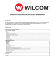
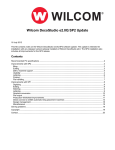
7
Troubleshooting
7.1.0 Error Messages and Handling
7.1.1 Main Shaft Motor and Others
No.
100
101
Error Name
Main shaft motor stop position
error
Main shaft motor driver error
Main shaft motor overload error
102
No trimming system recovery
103
104
Start switch error
105
Stop switch error
107
Valve error
Air pressure error
108
Pulley ratio error
109
110
AC Line error
Error Description
When it is stopped, the main
shaft’s angle is not 100˚
Main shaft motor driver develops
an error.
When a thread tangles the hook,
when the needle bar’s control
body is bad, and when the thread
becomes tangled during
trimming, the error occurs.
When the trimming sensor is not
recovered upon trimming.
When the power is on, the start
button is pressed.
When the power is on, the stop
button is pressed.
When the valve is opened.
When the air pressure is below
the standard (Sequin)
When the set pulley ratio is
wrong
When a problem occurs on the
joint board.
Correction
Use the lever to set the main
shaft’s angle at 100˚.
Turn off and on the main switch.
Check the hook of the front head,
and turn off and on the main
switch.
Check and respond to the
abnormality of the trimming
system.
Check whether the start button
contacts the connector.
Check whether the stop button
contacts the connector.
Change the driver setting after
checking the main shaft pulley
ratio.
Replace the joint board
7.1.2 X, Y Motor-related Errors
No.
Error Name
200
(+X) frame limit detection
201
(-X) frame limit detection
202
(+Y) frame limit detection
203
(-Y) frame limit detection
204
X-axis driver error
205
Y-axis driver error
206
207
Wiper return error
Trimmer return error
Error Description
The frame feed system reaches
the +X limit.
The frame feed system reaches
the -X limit.
The frame feed system reaches
the +Y limit.
The frame feed system reaches
the -Y limit.
Problems occur in the X-axis
driver.
Problems occur in the Y-axis
driver.
Wiper solenoid does not return.
Trimmer motor does not return.
7-1
Correction
Move the frame in the -X
direction.
Move the frame in the +X
direction.
Move the frame in the -Y
direction.
Move the frame in the +Y
direction.
Turn off and on the main switch.
Turn off and on the main switch.
Repairs the wiper mechanism.
Repair the trimmer mechanism.
7.1.3 Color Change
No.
300
Error Name
Needle bar stop position error
Error Description
When replacing the needle bar,
the needle bar fails to reach the
proper position.
Correction
Manually turns the needle bar to
check the load of the needle bar,
and place the needle bar at the stop
position.
7.1.4 Encoder
No.
Error Name
Error Description
400
Error in the main shaft encoder A
Problems in signaling occurred in
the main shaft’s encoder A.
Check the connection of the
encoder cable, and turn off and
then on the main switch.
Error in the main shaft encoder Z
Problems in signaling occurred in
the main shaft’s encoder Z.
Check the encoder’s cable
connection, and turn off and again
the main switch.
Error Name
Error Description
Correction
Error in consecutive work setting
As in (X-axis number)×(Y-axis
number)>99, the limit of
consecutive work was passed.
401
Correction
7.1.5 Consecutive Work
No.
501
7-2
Make sure that consecutive work
should be set as (X-axis number)
×(Y-axis number)<99.
7.1.6 Floppy Diskette and Communications
No.
Error Name
Error Description
Correction
No diskette.
There is no diskette inside the
FDD.
Insert a diskette into the FDD.
No sectors on the diskette
A floppy diskette is not formatted
or the format is different.
Format a diskette or replace it with
other diskette.
No design data in the diskette
There is no embroidery design
saved in a floppy diskette.
Replace the diskette.
Remove the write protect tap.
When copying embroidery
designs, the diskette write protect
tap is enabled.
Disable the write protect tap.
Diskette damaged
A floppy diskette is damaged.
Format a diskette or replace it.
Insufficient memory capacity
There is unoccupied space for
copying in a floppy diskette.
Replace the diskette with a new
one.
Diskette removed from FDD
A floppy diskette is removed in
the middle of FDD operation.
Insert the diskette and start are
work again.
607
Bad sector error during floppy
reading
The floppy diskette’s sector is
bad.
Format the diskette or replace it.
608
Bad sector error during floppy
writing
The floppy diskette’s sector is
bad.
Format the diskette or replace it.
Diskette error whose cause is
unknown
Errors are developed whose
cause is unknown while the
floppy diskette is in operation.
Format the diskette or replace it
with another one.
Diskette error
Errors are developed whose
cause is unknown, while the
floppy diskette is in operation.
Format the diskette or replace it
with another one.
600
601
602
603
604
605
606
609
610
611
ZSK design error
612
BARUDAN design error
613
Bad sector error
Operating program install error
When the operating program is
installed, the operating program
file name does not match or does
not exist.
Error found in the read data
The data read through the tape
reader develops errors.
Enter data through the tape reader
again.
Network device error
The network devices are not
connected.
Check the status of the network
devices.
USB error
The USB driver is not ready
Check whether the memory
system of the USB memory is
FAT16.
614
630
640
650
7-3
7.1.7 Memory
No.
Error Name
700
No embroidery data found in the
memory
The embroidery data does not
exist in the memory.
Use a floppy diskette or a USB to
save embroidery data.
Insufficient memory capacity
The data desired to copy in the
memory failed to be copied due
to the lack of memory capacity.
Delete unnecessary data.
100 memory rooms are full.
The 100 memory rooms are all
saved with designs.
Delete unnecessary data.
Error in design memory system
Errors have occurred during
copying or deleting data between
memory devices.
Press Reset or turn off and on the
main switch.
Bad memory battery
The battery is exhausted when
the power is off.
The status of saving the number
of stitches and the x, y position
information is unstable.
Call the A/S center at the nearest
to your place and replace the
battery.
If this error frequently occurs,
need to replace the CPU board.
Sequin design error
There is an error in the sequin
design.
Amend the design.
MC1 communications error
The CAN communications do not
regularly occur.
Check the cable and turn off and
on the power.
MC2 communications error
When the CAN communications
do not regularly occur.
Check the cable and turn off and
on the power.
701
702
703
704
801
901
902
Error Description
7-4
Correction
7.2.0 Machine Setting
7.2.1 Control Box Front
<Fig. 7.2.1-1> shows the front-side look of the control box.
③
①
④
②
[Fig. 7.2.1-1]
① Main Driver Rack
② I/O Board , XY Driver Rack
③ Power Rack
④ Main Switch
7-5
7.2.2 Fuse Install and Replace
Insert the power plug of the embroidery machine. If power remains off when pressing the power switch, take actions
following the below direction. Check the fuse location as in <Fig. 7.2.2-1> and replace the fuse with a new one.
<Control Box Rear Side>
Fuse in Use : AC250V , 4A
Fuse Quantity : 2
[Fig. 7.2.2-1]
Although the power switch is off, there still exists the risk of being electrified. Make sure that the power cord is
plugged off before staring embroidery work.
7-6
7.2.3 I/O Board , X/Y Driver Board Dip Switch Setting
<Fig. 7.2.2-1> shows I/O and XY Driver Board. The position of the board can be checked in“7.2.1 Control Box Front
Side”.
② I/O Board
① XY Driver Board
③ I/O Board Dip SW
⑤ Y Driver Board Dip SW
④ Y Driver Board Rotary SW
⑪ Y Driver Board Rotary SW 6
⑩ Y Driver Board Rotary SW 5
⑨ Y Driver Board Rotary SW 4
⑧ Y Driver Board Rotary SW 3
⑦ Y Driver Board Rotary SW 2
⑥ Y Driver Board Rotary SW 1
[Fig. 7.2.3-1]
① XY Driver Board
② I/O Board
7-7
③ I/O Board Dip Switch Setting
ON
OFF
1
2
3
4
OFF
ON
─
Reserved
─
─
Reserved
─
─
Reserved
─
─
Reserved
OFF
─
ON
─
Reserved
─
─
Reserved
─
─
Reserved
─
─
Reserved
─
─
Motor Setting
X motor
Y motor
SELFTEST MODE
Unused
Used
Function
CAN I/D Setting
④ X Driver Board Dip Switch Setting
ON
OFF
1
2
3
4
5
6
7
8
Function
M/C Choice
7-8
Upgrade
Compact
─
⑤ Y Driver Board Dip Switch Setting
ON
OFF
1
2
3
4
5
6
7
8
Reserved
OFF
─
ON
─
Reserved
─
─
Reserved
─
─
Reserved
─
─
Reserved
─
─
Motor setting
X motor
Y motor
SELFTEST MODE
Unused
Used
Function
M/C Choice
Upgrade
Compact
According to machine type, select Dip Switch No. 1 (For the current machine type, select“Off”.)
⑥ Rotary Switch 1
- Default -“0”
- Offset for X-Driver D gain OFFSET (D gain while dual gain is applied).
⑦ Rotary Switch 2
- Default -”0”
- Offset for X-Driver I gain (I gain while dual gain is applied).
⑧ Rotary Switch 3
- Default -”0”
- Offset for X-Driver P gain (P gain while dual gain is applied)
⑨ Rotary Switch 4
- Default -“0”
- Offset for Y-Driver D gain (D gain while dual gain is applied)
⑩ Rotary Switch 5
- Default -“0”
- Offset for Y-Driver I gain (I gain while dual gain is applied)
⑪ Rotary Switch 6
- Default -“0”
- Offset for Y-Driver P gain (P gain while dual gain is applied)
7-9
─
7.3 System Block Diagram
Block Diagram for Upgrade Compact Embroidery Machine
※ New Compact-type Automatic Embroidery Machine
[Fig. 7.3-1]
7-10
Block Diagram for Single head bridge automatic embroidery machine
※ Single head bridge automatic embroidery machine
[Fig. 7.3-2]
7-11