1
Installation
2.6.5
Manual Certify
The Manual Certify™ test feature performs a confidence test of the system by
duplicating the same signal as a high-level alarm condition without requiring
the system to be removed from the tank.
•
•
•
•
•
Simulating a high level with the Manual Certify feature:
Checks AutoVerify™ and system circuits to ensure proper operation.
Checks integrity and continuity of the wiring connections.
Verifies that sensing element is working properly.
Checks relay connections to other control devices.
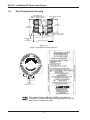
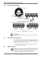
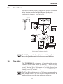
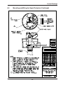
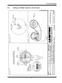
The Manual Certify test is initiated with the press of the Manual Certify
Button located on the sensing element/ circuit side of the housing. After
pressing the button, the Green LED flashes for 5 seconds and the two Red
LEDs illuminate. The relay contacts are moved to the alarm condition for 2
seconds. If the two Red LEDs do not light, and the relay contacts do not move to
the alarm condition, the Manual Certify test has detected a fault. Consult the
troubleshooting section of this Instruction Manual. Manual Certify is available
when system is configured for HLFS.
2.6.6AutoVerify
The AutoVerify™ feature in The IntelliPoint™ switch is shipped DISABLED.
For critical High Level applications we recommend enabling the AutoVerify™
feature.
AutoVerify™ is a self-test function that continuously checks the system for
proper operation when the unit is in the High Level FailSafe (HLFS) mode and
in normal condition.
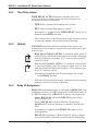
• ON: If fault is detected during AUTOVERIFY cycle, both relays will deenergize regardless of how relay #2 is assigned. If relay #2 is assigned to
fault, user can distinguish between fault alarm and alarm caused by a high
level in the tank.
• OFF: The AUTOVERIFY self-test function is not active.
• Instrument is supplied with AUTOVERIFY jumper set in OFF position.
• AutoVerify™ is field-selectable using a jumper located on sensing element/
circuit board side of housing.
• When a fault is detected, both Red LEDs flash and the relays de-energize.
2.6.7
AutoVerify Criteria
1. AutoVerify feature must be enabled.
2. The sensor must generate an uncovered capacitance value greater than 2 pF.
Typically, the active sensor length (active length = insertion length – cote
shield length) must be greater than 8 inches (200 mm).
3. Consult Factory for specialty sensors that may be available for shorter length
requirements.
4. Sensors that do not meet the above requirement can perform reliably for
level measurement detection, and will pass AutoVerify / Manual Certify tests,
but will not be able to detect a sensor that is, or has become, electrically
disconnected from the transmitter.
13