1
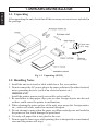
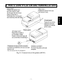
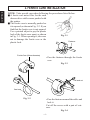
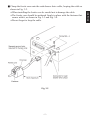
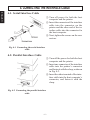
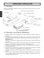
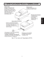
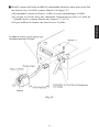
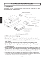
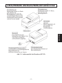
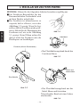
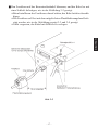
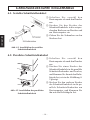
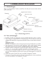
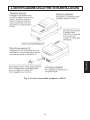
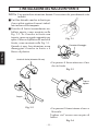
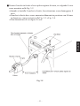
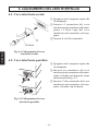
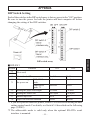
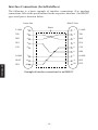
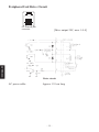
DOT MATRIX PRINTER
SP312F
SP342F-A
INSTALLATION MANUAL
GUIDE D’INSTALLATION
AUFSTELLANLEITUNG
MANUALE DI INSTALLAZIONE
TABLE OF CONTENTS
1. UNPACKING AND INSTALLATION ................................................ 2
1-1. Unpacking .................................................................................... 2
1-2. Handling Notes ............................................................................ 2
2. PARTS IDENTIFICATION AND NOMENCLATURE ...................... 3
3. FERRITE CORE INSTALLATION ..................................................... 4
4. CONNECTING THE INTERFACE CABLE ....................................... 6
4-1. Serial Interface Cable ................................................................... 6
4-2. Parallel Interface Cable ................................................................ 6
APPENDIX ............................................................................................. 25
1. UNPACKING AND INSTALLATION
ENGLISH
1-1. Unpacking
After unpacking the unit, check that all the necessary accessories are included in
the package.
Ferrite core
(E.U. only)
,,,,
,,,,
Ø28mm
Fastener
(E.U. only)
Fig. 1-1 Unpacking (SP312)
1-2. Handling Notes
1. Install the unit on a stand or table which has a flat, even surface.
2. Do not connect the AC power plug to the same outlet used for other electrical
noise generating devices (such as an electrical motor, etc.)
IMPORTANT!
Install the printer near an easily accessible socket-outlet.
3. Be careful not to drop paper clips, pins or other foreign objects into the unit
as these could cause the printer to malfunction.
4. When cleaning the outer surface of the unit, wipe away dirt, foreign matter,
etc., with a soft cloth, soaked in a neutral detergent.
5. Do not attempt to print when the paper or ribbon cartridge are not loaded in
the printer as this could damage the print head.
6. Use only roll paper that is not glued to the core.
7. Do not open the front cover while printing (this is interpreted as a mechanical
error and the printer will stop).
–2–
ENGLISH
2. PARTS IDENTIFICATION AND NOMENCLATURE
Fig. 2-1 External view of the printer (SP312)
–3–
3. FERRITE CORE INSTALLATION
ENGLISH
NOTE: Take special care when following the procedures listed below.
■ A ferrite core noise filter for the cash
drawer drive cable comes packed with
the printer.
■ The ferrite core is normally packed so
it is opened, as shown in Fig. 3-2. If you
find that the ferrite core is not opened:
Use a pointed object to pry the plastic
lock of the ferrite core apart, as shown
Fig. 3-1
in Fig. 3-1. When opening it, take care
not to damage the ferrite core or the
Fastener
plastic lock.
,,,
Ferrite Core (28mm diameter)
• Pass the fastener through the ferrite
core
Fig. 3-3
Pull and cut
One loop
Fig. 3-2
• Pass the fastener around the cable and
lock it.
Cut off the excess with a pair of scissors.
Fig. 3-4
–4–
• When installing the ferrite core be careful not to damage the cable.
• The ferrite core should be anchored firmly in place with the fastener that
comes with it, as shown in Fig. 3-3 and Fig. 3-4.
• Do not forget to loop the cable.
Fig. 3-5
–5–
ENGLISH
■ Clamp the ferrite core onto the cash drawer drive cable, looping the cable as
shown in Fig. 3-2.
4. CONNECTING THE INTERFACE CABLE
ENGLISH
4-1. Serial Interface Cable
1 Turn off power for both the host
computer and the printer.
2 Insert the connector of the interface
cable into the connector on the
printer and the other end of the interface cable into the connector for
the host computer.
3 Next, tighten the screws on the connectors.
Fig. 4-1 Connecting the serial interface
cable
4-2. Parallel Interface Cable
1 Turn off the power for both the host
computer and the printer.
2 Insert one connector of the interface
cable into the printer’s connector
and fasten it with the clasp, as shown
in Fig. 4-2.
3 Insert the other terminal of the interface cable into the host computer’s
connector, and fasten it with the
clasp.
Fig. 4-2 Connecting the parallel interface
cable
–6–
TABLE DES MATIÈRES
1. DÉBALLAGE ET INSTALLATION ................................................... 8
1-1. Déballage ..................................................................................... 8
1-2. Remarques concernant la manipulation ....................................... 8
2. IDENTIFICATION DES PIÈCES ET NOMENCLATURE ................ 9
3. INSTALLATION DU NOYAU EN FERRITE .................................. 10
4. CONNEXION DU CÂBLE D’INTERFACE ..................................... 12
4-1. Câble d’interface sériel .............................................................. 12
4-2. Câble d’interface parallèle ......................................................... 12
APPENDICE ........................................................................................... 25
L’appendice n’est pas traduit.
1. DÉBALLAGE ET INSTALLATION
1-1. Déballage
Après avoir déballé l’appareil, vérifiez si vous disposez bien de tous les accessoires illustrés ci-après.
FRANÇAIS
Fig. 1-1 Déballage (SP312)
1-2. Remarques concernant la manipulation
1. Installez l’appareil sur un support ou sur une table dont la surface est plate et
uniforme.
2. Ne branchez pas l’appareil à la même prise secteur que d’autres appareils
produisant des bruits électriques (appareils ayant un moteur électrique, etc.).
IMPORTANT !
Installez l’imprimante le plus près possible d’une prise secteur facilement
accessible.
3. Veillez à ne pas laisser tomber des trombones, punaises ou autres objets dans
l’appareil, cela risque de causer un mauvais fonctionnement.
4. Nettoyez la surface de l’imprimante à l’aide d’un chiffon doux humidifié et
d’un détergent neutre.
5. Ne lancez pas l’impression si le papier ou la cartouche de ruban ne sont pas
installés, sous peine d’endommager la tête d’impression.
6. N’utilisez jamais un rouleau de papier dont l’extrémité est collée au rouleau
central.
7. N’ouvrez pas le cache avant de l’appareil pendant l’impression ; en effet cela
serait interprété comme étant une erreur mécanique et l’impression s’interromprait automatiquement.
–8–
FRANÇAIS
2. IDENTIFICATION DES PIÈCES ET NOMENCLATURE
Fig. 2-1 Vue externe de l’imprimante (SP312)
–9–
3. INSTALLATION DU NOYAU EN FERRITE
FRANÇAIS
N.B.: Effectuez cette installation avec beaucoup de soin.
■ Un filtre antibruit en noyau en ferrite
destiné au câble de commande d’un
tiroir-caisse est livré avec l’imprimante.
■ Le noyau en ferrite devrait normalement être ouvert, comme illustré à la
figure 3-2. Si votre noyau en ferrite
n’est pas ouvert, il convient de l’ouvrir
en faisant levier à l’aide d’un objet
Fig. 3-1
pointu, ainsi qu’illustré à la figure 3-1.
En l’ouvrant, veillez bien à ne pas endommager ni le noyau en ferrite ni le
Attache
verrouillage en plastique.
,,,
Tore de ferrite (28 mm de diamètre)
• Faire passer l’attache par le guide du
noyau en ferrite.
Fig. 3-3
Tirer et couper
Une boucle
Fig. 3-2
• Faire passer l’attache autour de la
boucle du câble et verrouiller.
Coupez le bout de plastique qui dépasse à l’aide d’une paire de ciseaux.
Fig. 3-4
– 10 –
■ Brider le noyau en ferrite au câble de commande du tiroir-caisse après avoir fait
une boucle avec le câble, comme illustré à la figure 3-2.
• En montant le noyau en ferrite, veillez à ne pas endommager le câble.
• Le noyau en ferrite doit être maintenu fermement en place à l’aide de
l’attache livrée, comme illustré aux figures 3-3 et 3-4.
FRANÇAIS
• Ne pas oublier de former une boucle avec le câble.
Fig. 3-5
– 11 –
4. CONNEXION DU CÂBLE D’INTERFACE
4-1. Câble d’interface sériel
FRANÇAIS
1 Mettez l’ordinateur hôte et
l’imprimante hors tension.
2 Insérez un des connecteurs du câble
d’interface dans la prise de
l’imprimante et l’autre dans la prise
de l’ordinateur hôte.
3 Serrez ensuite les vis des
connecteurs.
Fig. 4-1 Connexion du câble d’interface
en série
4-2. Câble d’interface parallèle
1 Mettez l’ordinateur hôte et
l’imprimante hors tension.
2 Insérez un des connecteurs du câble
d’interface dans la prise de
l’imprimante et fixez-le grâce aux
fermoirs, comme illustré à la fig. 42.
3 Insérez l’autre connecteur du câble
d’interface dans la prise de l’ordinateur hôte, puis fixez-le également à
l’aide des fermoirs.
Fig. 4-2 Connexion du câble d’interface
en parallèle
– 12 –
INHALTSVERZEICHNIS
1. AUSPACKEN UND AUFSTELLUNG .............................................. 14
1-1. Auspacken .................................................................................. 14
1-2. Hinweise zum Umgang .............................................................. 14
2. BESCHREIBUNG UND BEZEICHNUNG DER GERÄTETEILE .. 15
3. INSTALLATION DES FERRITKERNS ............................................ 16
4. ANSCHLUSS DES SCHNITTSTELLENKABELS .......................... 18
4-1. Serielles Schnittstellenkabel ...................................................... 18
4-2. Paralleles Schnittstellenkabel ..................................................... 18
ANHANG ................................................................................................ 25
Der Anhang erscheint nur im englischen Teil dieser Bedienungsanleitung
1. AUSPACKEN UND AUFSTELLUNG
1-1. Auspacken
Überprüfen Sie den Kartoninhalt, und vergewissern Sie sich, daß alle unten
abgebildeten Teile vorhanden sind.
DEUTSCH
Abb. 1-1 Auspacken (SP312)
1-2. Hinweise zum Umgang
1. Stellen Sie den Drucker auf einem flachen, aber festen Untergrund auf.
2. Schließen Sie keine anderen elektrischen Geräte, die elektrische Störungen
erzeugen (wie z.B. Elektromotoren) an die gleiche Steckdose an.
WICHTIG!
Die verwendete Steckdose soll in der Nähe und frei zugänglich sein.
3. Achten Sie darauf, keine Papierclips oder anderen Fremdkörper in den
Drucker fallen zu lassen. Diese können Betriebsstörungen oder Schäden am
Gerät hervorrufen.
4. Bei der Reinigung des Geräteäußeren wischen Sie Flecken oder Schmutz mit
einem weichen, mit neutralem Reinigungsmittel angefeuchteten Lappen ab.
5. Versuchen Sie nicht zu drucken, wenn kein Papier oder keine Farbbandkassette eingelegt ist, da sonst der Druckkopf beschädigt werden kann.
6. Verwenden Sie nur Rollenpapier, das nicht am Rollenkern festgeklebt ist.
7. Öffnen Sie nicht die Frontabdeckung während des Druckens (dies wird als
mechanische Störung beurteilt, und der Drucker stoppt).
– 14 –
DEUTSCH
2. BESCHREIBUNG UND BEZEICHNUNG DER GERÄTETEILE
Abb. 2-1 Außenansicht des Druckers (SP312)
– 15 –
3. INSTALLATION DES FERRITKERNS
DEUTSCH
HINWEIS: Führen Sie die folgenden Arbeiten besonders sorgfältig aus.
■ Ein Ferritkern-Rauschfilter für das
Kassenschubladen-Treiberkabel wird
mit dem Drucker mitgeliefert.
■ Der Ferritkern ist normalerweise so
verpackt, daß er offen ist, wie in der
Abbildung 3-2 gezeigt. Wenn Sie feststellen, daß der Ferritkern nicht geöffnet ist: Hebeln Sie die Plastiksperre des
Abb. 3-1
Ferritkerns auf, wie in der Abbildung
3-1 gezeigt. Beim Öffnen achten Sie
Kabelband
darauf, nicht den Ferritkern oder die
Plastiksperre zu beschädigen.
,,,
Ferritkern (28 mm Durchmesser)
• Das Plastikhalterungsband durch den
Ferritkern führen.
Abb. 3-3
Ziehen und
abschneiden
Eine Schleife
Abb. 3-2
• Das Plastikhalterungsband um das
Kabel führen und festziehen.
Überstehendes Band mit einer Schere
abschneiden.
Abb. 3-4
– 16 –
■ Den Ferritkern auf das Kassentreiberkabel klemmen, und das Kabel so mit
einer Schleife befestigen, wie in der Abbildung 3-2 gezeigt.
• Beim Installieren des Ferritkerns darauf achten, das Kabel nicht zu beschä-
DEUTSCH
digen.
• Der Ferritkern soll fest mit dem mitgelieferten Plastikhalterungsband befestigt werden, wie in der Abbildung gezeigt 3-3 und 3-4 gezeigt.
• Nicht vergessen, das Kabel mit Schleife zu verlegen.
Abb. 3-5
– 17 –
4. ANSCHLUSS DES SCHNITTSTELLENKABELS
4-1. Serielles Schnittstellenkabel
DEUTSCH
1 Schalten Sie sowohl den
Hostcomputer als auch den Drucker
aus.
2 Stecken Sie den Stecker des
Schnittstellenkabels in die entsprechenden Buchsen am Drucker und
am Hostcomputer ein.
3 Ziehen Sie die Schrauben an den
Steckern fest.
Abb. 4-1 Anschließen des seriellen
Schnittstellenkabels
4-2. Paralleles Schnittstellenkabel
Abb. 4-2 Anschließen des parallelen
Schnittstellenkabels
1 Schalten Sie sowohl den
Hostcomputer als auch den Drucker
aus.
2 Stecken Sie einen Stecker des
Schnittstellenkabels in die parallele
Schnittstellenbuchse am Drucker,
und klemmen Sie ihn mit den Haltebügeln fest, wie in der Abbildung 42 gezeigt.
3 Stecken Sie den anderen Stecker
des Schnittstellenkabels in die parallele Schnittstellenbuchse am
Hostcomputer, und klemmen Sie
ihn mit den Haltebügeln fest.
– 18 –
INDICE
1. DISIMBALLAGGIO E INSTALLAZIONE ...................................... 20
1-1. Disimballaggio ........................................................................... 20
1-2. Note sul maneggio ..................................................................... 20
2. IDENTIFICAZIONE DELLE PARTI E NOMENCLATURA .......... 21
3. INSTALLAZIONE DEL NUCLEO IN FERRITE ............................. 22
4. COLLEGAMENTO DEL CAVO INTERFACCIA ............................ 24
4-1. Cavo interfaccia seriale .............................................................. 24
4-2. Cavo interfaccia parallelo .......................................................... 24
APPENDICE ........................................................................................... 25
L’Appendice appare solo nella sezione in inglese di questo manuale.
1. DISIMBALLAGGIO E INSTALLAZIONE
1-1. Disimballaggio
Dopo aver disimballato l’unità, controllare che tutti gli accessori siano inclusi
nella confezione.
ITALIANO
Fig. 1-1 Disimballaggio (SP312)
1-2. Note sul maneggio
1. Installare l’unità su un appoggio o un tavolo dalla superficie piana e regolare.
2. Non collegare la spina del cavo di alimentazione CA ad una presa cui sono
collegati altri dispositivi che generano disturbi elettrici (come motori elettirici,
ecc.).
IMPORTANTE!
Installare la stampante vicino ad una presa di corrente facilmente accessibile.
3. Fare attenzione a non lasciar cadere graffette, spilli o altri oggetti estranei
nell’unità perché possono causare malfunzionamenti della stampante.
4. Quando si pulisce la superficie esterna dell’unità, togliere lo sporco, materiali
estranei, ecc. con un panno morbido inumidito con detergente neutro.
5. Non tentare di stampare quando la carta o la cartuccia del nastro non sono
inserite nella stampante perchè tale azione può danneggiare la testina di
stampa.
6. Usare solo carta in rotolo che non è incollata al supporto centrale.
7. Non aprire il coperchio anteriore durante la stampa (questo viene considerato
un errore meccanico e la stampante si ferma).
– 20 –
ITALIANO
2. IDENTIFICAZIONE DELLE PARTI E NOMENCLATURA
Fig. 2-1 Vista esterna della stampante (SP312)
– 21 –
3. INSTALLAZIONE DEL NUCLEO IN FERRITE
ITALIANO
NOTA: Fare particolare attenzione durante l’esecuzione dei procedimenti sotto
indicati.
■ Un filtro disturbi a nucleo in ferrite per
il cavo pilota registro di cassa è imballato insieme alla stampante.
■ Il nucleo di ferrite ènormalmente imballato aperto, come mostrato nella
Fig. 3-2. Se il nucleo in ferrite non
èaperto, usare un oggetto appuntito per
Fig. 3-1
aprire il blocco di plastica del nucleo di
ferrite, come mostrato nella Fig. 3-1.
Fascetta di fissaggio
Quando si apre, fare attenzione a non
danneggiare il nucleo in ferrite o il
blocco di plastica.
,,,
Anello di ferrite (diametro 28 mm)
• Far passare il fermo attraverso il nucleo in ferrite.
Fig. 3-3
Tirare e
tagliare
Cappio
Fig. 3-2
• Far passare il fermo interno al cavo e
bloccarlo.
Tagliare via l’eccesso con un paio di
forbici.
Fig. 3-4
– 22 –
■ Fissare il nucleo in ferrite al cavo pilota registro di cassa, avvolgendo il cavo
come mostrato nella Fig. 3-2.
• Quando si installa il nucleo in ferrite, fare attenzione a non danneggiare il
ITALIANO
cavo.
• Il nucleo in ferrite deve essere ancorato saldamente in posizione con il fermo
in dotazione, come mostrato nella Fig. 3-3 e Fig. 3-4.
• Non dimenticare di avvolgere il cavo.
Fig. 3-5
– 23 –
4. COLLEGAMENTO DEL CAVO INTERFACCIA
4-1. Cavo interfaccia seriale
1 Spegnere sia il computer ospite che
la stampante.
2 Inserire il connettore del cavo
interfaccia nel connettore sulla stampante e l’altro capo del cavo
interfaccia nel connettore sul computer.
3 Serrare le viti dei connettori.
ITALIANO
Fig. 4-1 Collegamento del cavo
interfaccia seriale
4-2. Cavo interfaccia parallelo
1 Spegnere sia il computer ospite che
la stampante.
2 Inserire un connettore del cavo
interfaccia nel connettore sulla stampante e fissarlo con la morsa, come
mostrato nella Fig. 4-2.
3 Inserire l’altro terminale del cavo
interfaccia nel connettore sul computer e fissarlo con la morsa.
Fig. 4-2 Collegamento del cavo
interfaccia parallelo
– 24 –
APPENDIX
DIP Switch Setting
DIP switch array
■ DIP-SW 1
Switch
1-1
1-2
1-3
1-4
*1
1-5
1-6
1-7
1-8
Function
ON
OFF
(Not used)
Control code CR
When turning
DC1, DC 3
the power on.
mode
Addressable
mode *2
Setting the paper feed length
Setting the buffer size
Backed up RAM
Paper out detection function
Invalid
Select
Valid
Deselect
Deselect
Select
1/6-inch
4 K-bytes
YES
Valid
1/8-inch
256 bytes
NO
Invalid
*1 If you use a parallel interface printer, Switch 1-4 is used for switching the auto
cutting control mode. For details, see Switch 3-4 described on the following
page. (SP342)
*2 The addressable mode is valid only when the optional RS-422A serial
interface is mounted.
– 25 –
APPENDIX
Each of the switches in the DIP switch array is factory preset to the “ON” position.
Be sure to turn the power for both the printer and host computer off before
changing the setting of the DIP switches.
■ DIP-SW 2
Switch
Function
2-1
Character code table
2-2
2-3
(Not used)
2-4
Setting the paper width
2-5
2-6
2-7
2-8
(Not used)
ON
OFF
See table below.
3.25-inch,
3.0-inch
International character set
2.25-inch
See table below.
■ Character code table (switches 2-1, 2-2)
Switch
2-1
2-2
U.S.A. & Europe
ON
ON
IBM #1
OFF
ON
IBM #2
ON
OFF
Japan
OFF
OFF
■ International character set (Switches 2-6, 2-7 and 2-8)
APPENDIX
Switch U.S.A.
2-6
ON
2-7
ON
2-8
ON
France Germany England Denmark Sweden
OFF
ON
OFF
ON
OFF
ON
OFF
OFF
ON
ON
ON
ON
ON
OFF
OFF
Italy
ON
OFF
OFF
Spain
OFF
OFF
OFF
■ DIP-SW 3 (For serial interface type only)
Switch
Function
3-1
3-2
Data transmission rate
3-3
Auto cutting
3-4
control mode *3 (SP342)
3-5
Data composition
3-6
Data word length
3-7
Vertical parity check
3-8
Parity
ON
OFF
See next page
Invalid
Valid
DTR mode
8-data bit
No parity check
Odd parity
X-ON/X-OFF mode
7-data bit
Parity check
Even parity
*3 When a command is given to continuously feed paper over 7/6 inches in the
auto cutting control mode, the paper will be fully cut.
– 26 –
■ Data transmission rate (baud rate)
Baud rate
150 bps
300 bps
600 bps
1200 bps
2400 bps
4800 bps
9600 bps
3-1
OFF
OFF
OFF
OFF
ON
ON
ON
3-2
OFF
OFF
ON
ON
OFF
OFF
ON
3-3
OFF
ON
OFF
ON
OFF
ON
ON/OFF
■ DIP SW 4 (For serial interface type only)
Function DC1, DC3
Switch
invalid mode #1 #2
4-1
ON OFF ON
4-2
ON ON OFF
4-3
ON ON ON
4-4
ON ON ON
Addressable mode *4
DC1, DC3
#3 #4 #5 #6 #7 #8 #9 #10 #11 #12 #13 #14 valid mode
OFF ON OFF ON OFF ON OFF ON OFF ON OFF ON OFF
OFF ON ON OFF OFF ON ON OFF OFF ON ON OFF OFF
ON OFF OFF OFF OFF ON ON ON ON OFF OFF OFF OFF
ON ON ON ON ON OFF OFF OFF OFF OFF OFF OFF OFF
APPENDIX
*4 The addressable mode is valid only when an optional RS-422A serial interface
is mounted.
– 27 –
Connectors and Signals (Serial Interface)
RS-232C
Pin no.
I/O
direction
Signal name
Function
APPENDIX
1
2
F-GND
TXD
—
OUT
Frame ground
Transmitted data
3
4
RXD
RTS
IN
OUT
Received data
Data transmission request signal. This
is always “SPACE” when the printer is
turned on.
5
CTS
IN
6
N/C
This signal changes to “SPACE” when
host computer is ready to transmit data.
(In this instance, the printer does not
check this signal.)
Not connected
7
8
S-GND
N/C
—
Signal ground
Not connected
9-10
N/C
11
RCH
12
13
N/C
S-GND
—
14
FAULT
OUT
15
Multi-printer TXD
OUT
16
17 to 19
Multi-printer DTR
N/C
OUT
Diode coupled DTR
This pin is used when using the optional interface board.
20
DTR
OUT
21-22
N/C
Data terminal ready signal. When the
printer is ready to receive data, this
signal changes to “SPACE”.
Not connected
23 to 25
N/C
OUT
This pin is used when using the optional interface board.
This signal changes to “SPACE” when
the printer is ready to receive data. (The
signal line is same as pin 20.)
Not connected.
Signal ground
When a printer error occurs (such as
paper out, mechanical error, etc.), this
signal is set to “MARK”.
Diode coupled TXD
This pin is used when using the optional interface board.
14
25
13
1
Serial interface connector
– 28 –
20 mA current loop (option)
Pin no.
Signal name
I/O
direction
Function
9
TTY TXDR
—
Indicates the ground side of the data
signal of 20 mA loop current.
Transmitted data of 20 mA current
loop.
10
TTY TXD
OUT
17
TTY TXDR
—
18
TTY RXDR
—
19
23
TTY RXD
TTY RXDR
IN
—
Received data of 20 mA current loop.
Indicates the ground side of the data
signal at 20mA loop current.
24
TTY TXD
OUT
25
TTY RXD
IN
Transmission data of 20 mA current
loop.
Reception data of 20 mA current loop.
Indicates the ground side of the data
signal of 20 mA loop current.
Indicates the ground side of the data
signal of 20 mA loop current.
SD (+)
I/O
direction
OUT
Transmitted data
10
SD (–)
OUT
Transmitted data
17
RD (+)
IN
Received data
18
19
RD (–)
CS (+)
IN
IN
23
CS (–)
IN
24
RS (+)
OUT
Received data
When the host computer is set to standby
for data transmission, this signal
changes to “SPACE”.
(In this instance, the printer does not
check the signal.)
When the host computer is set to standby
for data transmission, this signal
changes to “SPACE”.
(In this instance, the printer does not
check the signal.)
Data transmission request signal. When
the printer is ready to receive data, this
signal changes to “SPACE”.
25
RS (–)
OUT
Pin no.
9
Signal name
– 29 –
Function
Data transmission request signal. When
the printer is ready to receive data, this
signal changes to “SPACE”.
APPENDIX
RS-422A (option)
Interface Connections (Serial Intefface)
The following is a basic example of interface connections. (For interface
connections, refer to the specifications for the respective interface.) An IBM PC
type serial port is shown in below.
IBM PC Side
Printer Side
Shield
F–GND
1
1
F–GND
TXD
2
2
TXD
RXD
3
3
RXD
RTS
4
4
RTS
CTS
5
5
CTS
6
DSR
APPENDIX
S–GND
7
7
S–GND
FAULT
14
8
DCD
DTR
20
20
DTR
Example of interface connections for an IBM PC
– 30 –
Connectors and Signals (Parallel Interface)
IN
2-9
DATA1-8
IN
10
ACK
OUT
11
BUSY
OUT
12
18
19-30
31
PAPER
OUT
OUT
SELECTED OUT
N/C
SIGNAL
GND
CHASSIS
GND
+5VDC
GND
RESET
IN
32
ERROR
33
34
35-36
EXT GND
COMPULSION OUT
N/C
13
14-15
16
17
(19)
IN/OUT
Function
Signals when data is ready to be read. Signal goes
from HIGH to LOW (for at least 0.5 microsec.)
when the data is available.
These signals provide the information of the first
to eighth bits of parallel data. Each signal is at
HIGH level for a logical 1 and at a LOW level for
a logical 0.
A 9 microsecond LOW pulse acknowledges receipt of the data.
When this signal goes to LOW, the printer is
ready to accept data. When the printer is in one of
the conditions below, “HIGH” is set.
1. Data is being entered.
2. Off line.
3. Error condition.
This signal is normally LOW. It will go to HIGH
if the printer runs out of paper.
This signal is HIGH when the printer is online.
Unused
Signal ground.
Chassis ground, isolated from logic ground.
+5VDC (Max 50 mA)
Twisted pair return the signal to ground level.
When this signal goes to LOW, the printer is reset
to its power-on condition.
This signal is normally HIGH. This signal goes to
LOW to signal that the printer cannot print due to
an error condition.
Refer to Item 8-4 Emergency Suspension.
External ground.
Compulsion signal
Unused.
OUT
(36)
This connector mates with an Amphenol
57-30360 connector
(1)
(18)
Parallel interface connector (printer side)
– 31 –
APPENDIX
1
Signal
Name
STROBE
Pin No.
Peripheral Unit Drive Circuit
6
1
6-P modular jack
connecter
[Drive output 24V, max. 1.0 A]
APPENDIX
Drive circuit
AC power cable:
Approx. 155 cm long
– 32 –
ELECTRONIC PRODUCTS DIVISION
STAR MICRONICS CO., LTD.
OVERSEAS SUBSIDIARY COMPANIES
STAR MICRONICS AMERICA, INC.
536 Nanatsushinya, Shimizu, Shizuoka,
424-0066 Japan
Tel: 0543-47-0112, Fax: 0543-48-5013
1150 King Georges Post Road, Edison, NJ 08837-3729 U.S.A.
Tel: 732-623-5555, Fax: 732-623-5590
http://www.starmicronics.com
Please access the following URL
http://www.star-micronics.co.jp/service/
frame_sp_spr_e.htm
for the lastest revision of the manual.
STAR MICRONICS U.K. LTD.
Star House, Peregrine Business Park, Gomm Road,
High Wycombe, Bucks, HP13 7DL, U.K.
Tel: 01494-471111, Fax: 01494-473333
http://www.starmicronics.co.uk
2000.04.10
Printed in Japan, 80871016


![User's Manual DP8340II SERIES [Serial]](http://vs1.manualzilla.com/store/data/006863352_1-7c329c58d43827994f443f796586090a-150x150.png)


![User`s Manual DP8340II R SERIES [Serial]](http://vs1.manualzilla.com/store/data/005993516_1-f706d7540b19c5fecea062c6335f03cc-150x150.png)