1
Dot Matrix Printer
SP300 Series
Programmer’s Manual
TABLE OF CONTENTS
1. CONTROL PANEL .............................................................................. 1
1-1. Basic Operation ............................................................................ 1
1-2. Switch Operation (Combined Switch Operation) ........................ 2
2. SERIAL INTERFACE .......................................................................... 7
2-1. Interface Specifications ................................................................ 7
2-2. Interface Circuit ........................................................................... 8
2-2-1. RS-232C Serial Interface .................................................. 8
2-2-2. Current Loop (option) ....................................................... 8
2-2-3. RS-422A Serial Interface (option) .................................... 9
2-3. Connectors and Signals .............................................................. 10
2-4. Interface Connections ................................................................. 12
2-5. Installing the Optional Interface Board ...................................... 13
2-6. Data Structure ............................................................................. 14
2-6-1. DTR mode ....................................................................... 14
2-6-2. X-ON/X-OFF mode ........................................................ 16
2-6-3. STX-ETX mode ............................................................. 19
3. PARALLEL INTERFACE .................................................................. 22
3-1. Interface Specifications .............................................................. 22
3-2. Interface Timing ......................................................................... 22
3-3. Connectors and Signals .............................................................. 24
4. Emergency Suspension ........................................................................ 25
5. VALIDATION PRINTING (Models with validation function only) . 26
5-1. Operating Method ...................................................................... 26
5-2. Printing Format .......................................................................... 27
5-3. Data format ................................................................................. 27
5-4. Other ........................................................................................... 27
6. AUTO CUTTER (Auto-cutting models only) ..................................... 28
6-1. Cutting Method .......................................................................... 28
6-2. Cutting position .......................................................................... 28
6-3. Auto cutting control codes ......................................................... 28
6-4. Other position to be observed .................................................... 28
7. CONTROL CODES ............................................................................ 29
7-1. Control Codes Used for Character Setting ................................. 32
7-2. Control Codes Used for Line Spacing ....................................... 36
7-3. Control Codes Used for Page Layout ......................................... 37
7-4. Control Codes Used for Graphics Printing ................................ 41
7-5. Control Codes Used for Download Characters .......................... 46
7-6. Control Codes Used for Peripheral Units ................................... 49
7-7. Other Control Codes .................................................................. 50
8. CHARACTOR CODE TABLES ...................................................... 55
8.1 U.S.A. & Europe (DIP SW2-1: ON, SW2-2: ON) ..................... 55
8.2 IBM Character Set #1 (DIP SW2-1: OFF, SW2-2: ON) .......... 57
8.3 IBM Character Set #2 (DIP SW2-1: ON, SW2-2: OFF) ........... 59
8.4 JAPAN (DIP SW2-1:, OFF, SW2-2: OFF) ................................ 61
8.5 International Character Sets ....................................................... 63
• For DIP switch settings, refer to Installation Manual.
• Models with validation function: SP312F, SP317F
1. CONTROL PANEL
1-1. Basic Operation
POWER
ALARM
3
4
5
ON LINE
1
FEED
2
Fig. 1-1 Control panel
1 “ON LINE” switch
Switches the printer between “ON
LINE” and “OFF LINE”. Whenever the printer switches between
“ON LINE” and “OFF LINE”, the
buzzer gives one short beep (“ON
LINE” and “OFF LINE”, switching
is possible only when the paper is
loaded in the printer.)
2 “FEED” switch
• When this switch is pressed and
then released within 0.5 sec.,the
paper feeds one line.
• When this switch is depressed for
more than 0.5 sec.,the paper feeds
continuously.
(The above paper feed operation
is possible for both “ON LINE”
and “OFF LINE” modes.)
3 “POWER” lamp (green LED)
• Lights when the power for the printer is on.
4 “ALARM” lamp (red LED)
• Lights when the paper is out.
If the paper is out, load a new roll then press the “ON LINE” switch.
• Flashes when the front cover is open or a mechanical error (motor lock etc.)
occurs. The buzzer will give one short beep followed by a long beep.
Mount the front cover properly and press the “ON LINE” switch. If the
buzzer still sounds and the “ALARM” lamp flashes, this signifies that a
mechanical error has occurred. Locate the cause of the error and turn the
power for the printer off and back on again to reset the printer.
(In case of a mechanical error, the data will not be cleared even if the power
is turned off.)
5 “ON LINE” lamp (green LED)
LED lit: Printer is ON LINE
LED off: Printer is OFF LINE
LED flashes: Validation printing mode is set.
When all lamps 3 to 5 light simultaneously and the buzzer sounds continuously, a CPU error has occurred. In case of a CPU error, turn off the power then
turn it on again. When turning off the power, the data will be cleared.
–1–
1-2. Switch Operation (Combined Switch Operation)
1 <SELF PRINT TEST>
FEED + POWER ON (Turn the power on while holding the FEED switch
depressed.)
Self-printing will be performed according to the VER. NO., DIP switch
settings and character order. When the FEED switch is held continuously
during self printing, only the characters will print out repeatedly.
In models with cutter, cutting will be done after self-printing is performed
according to the VER. NO., DIP switch setting and character order. When the
FEED switch is pressed after completed self-printing, character printing and
cutting will be repeatedly performed.
Fig. 1-2 Self printing sample (when using serial interface printer)
–2–
2 <Hexadecimal dump mode>
ON LINE + POWER ON (Turn the power on while holding the ON LINE
switch depressed.)
Each of the signals sent from the computer to the printer will be printed out
in hexadecimal code.
This function allows you to check if a control code sent to the printer by the
program being used is correct or not. The buzzer will sound once to indicate
the printer is in hexadecimal dump mode.
After the program has been run, the last line buffer should be flushed by
pressing the ON LINE switch. To turn off the mode, it is necessary to turn off
the printer completely.
Fig. 1-3 Hexadecimal printing sample
3 <CLEAR PRINT BUFFER> (Single Head Only)
FEED + ON LINE + POWER ON (Turn the power on while holding both
the FEED and ON LINE switches depressed.)
This operation clears the printer buffer. (The buzzer gives two short beeps.)
When DIP switch 1-7 of this printer is set to ON (which is the factory presetting),
the RAM back-up function operates to maintain the data in the data buffer, even
if the power for the printer is shut off due to power failure, etc.
However, when the printer power is shut off for more than 10 hours, the data
content will become unstable and its content could degenerate and become unusable in the worst instances. For this reason, when the printer power is turned
off for more than 10 hours, perform the above operation to clear the data in the
data buffer.
Note that the data in the buffer can also be cleared by control code <CAN>.
4 <MICRO FEED>
ON LINE + FEED Press the FEED switch while holding the ON LINE
switch depressed when the printer is OFF LINE and the paper will feed in very
small increments.
–3–
5 <PAGE TOP> (Sprocket-type Only)
ON LINE + FEED (Press the FEED button while holding the ON LINE
button depressed when the printer is ON LINE) The buzzer gives three short
beeps and the printer sets the page top.
6 <Dot alignment adjust mode> (Twin Head Only)
FEED + ON LINE + POWER ON
This mode enables adjustment of the forward and backward printed line alignment by 1/2-dot increments. The adjustment procedure is explained on the
following pages.
–4–
1. Enter the Dot Alignment Adjust Mode by turning on the power while
pressing the ONLINE and FEED switches.
2. When Dot Alignment Adjust Mode starts, the buzzer will sound twice and
“Dot Alignment Adjust Mode” is printed.
3. Seven dot alignment patterns are printed as shown below. The patterns are
arranged with the backward printed lines more toward the left as the patterns
are printed down the page; the fourth pattern is the standard. The asterisk (*)
indicates the pattern printed with the current setting.
–5–
4. To choose a pattern with a closer alignment of the forward and backward
printed lines, count from the top down to the desired pattern and press the
FEED switch the counted number of times. (The buzzer sounds each time the
FEED switch is pressed, up to a maximum of seven times. However, if the
FEED switch is pressed more than seven times, a warning sounds.)
5. Press the ONLINE switch after the setting is made. (If the power is turned off
before the ONLINE switch is pressed, the new setting becomes invalid.)
When the setting is entered, the buzzer sounds once and the chosen starting
position of the backward printed line is stored in the memory.
This setting does not change if the machine’s power is turned off.
A pattern using the selected setting and followed by “Adjust Completed!” is
printed.
If the ONLINE switch is pressed to end step 5 without changing the setting,
“Adjust Completed!” is printed and the mode is exited.
* To set the starting position of the backward printed line to 0, simultaneously
press the ONLINE and FEED switches in step 4. The mode automatically
continues on to step 5, then a pattern using the selected setting and followed
by “Adjust Completed!” is printed.
–6–
2. SERIAL INTERFACE
2-1. Interface Specifications
1 Data transmission method:
2 Baud rate:
Asynchronous serial interface
Selectable from 150, 300, 600, 1200,
2400, 4800, 9600, 19200 (Twin Head
only) bps (Refer to Installation
Manual.)
Start bit: 1 bit
Data bit: 7 or 8 bits (selectable. Refer
to Installation Manual.)
Parity bit: Odd, even or none
(selectable. Refer to Installation
Manual.)
Stop bit: 1 or 2 bit length
RS-232C (Standard feature)
MARK : Logic “1”(–3V to –25V)
SPACE : Logic “0” (+3V to +25V)
Current loop (optional)
MARK : Logic “1”(current ON)
SPACE : Logic “0” (current OFF)
RS-422A (Optional)
MARK : Logic “1”
A is –0.2V or less than B
SPACE : Logic “0”
A is 0.2V or more than B
3 Word length
4 Signal polarity
Mark [1]
b0
Space [0]
b1
b2
b3
A
b4
B
b5
b6
(b7)
C
D
A: Start bit
B: Data bits
C: Vertical parity bit
D: Stop bit
–7–
2-2. Interface Circuit
2-2-1. RS-232C Serial Interface
Input (RXD, CTS)
Printer
Host computer
75189 or equivalent
Output (DTR, FAULT, TXD, RCH, RTS)
Printer
Host computer
75188 or equivalent
Fig . 2-1 RS-232C interface circuit
2-2-2. Current Loop (option)
Input (TTY-RXD, TTY-RXDR)
Host computer
+V
R
Printer
Output (TTY-TXD, TTY-TXDR)
Host computer
+V
R
Printer
Note: Adjust “R” so that the loop current is set within 10 to 20 mA.
Fig. 2-2 Current loop interface circuit
–8–
2-2-3. RS-422A Serial Interface (option)
Input (RD, RS)
Printer
Host computer
A
B
Output (SD, CS)
Printer
Host computer
A
B
Fig. 2-3 RS-422A interface circuit
–9–
2-3. Connectors and Signals
RS-232C
Pin no.
Signal name
1
2
3
4
F-GND
TXD
RXD
RTS
I/O
direction
—
OUT
IN
OUT
5
CTS
IN
6
7
8
9-10
N/C
S-GND
N/C
N/C
11
RCH
OUT
12
13
14
N/C
S-GND
FAULT
—
OUT
15
16
17 to 19
Multi-printer TXD
Multi-printer DTR
N/C
OUT
OUT
20
DTR
OUT
21-22
23 to 25
N/C
N/C
—
Function
Frame ground
Transmitted data
Received data
Data transmission request signal. This is always “SPACE” when the printer is turned on.
This signal changes to “SPACE” when
host computer is ready to transmit data. (In
this instance, the printer does not check this
signal.)
Not connected
Signal ground
Not connected
This pin is used when using the optional
interface board.
This signal changes to “SPACE” when the
printer is ready to receive data. (The signal
line is same as pin 20.)
Not connected.
Signal ground
When printer error occurs (such as paper
out, mechanical error, etc.), this signal is
set to “MARK”.
Diode coupled TXD
Diode coupled DTR
This pin is used when using the optional
interface board.
Data terminal ready signal. When the printer
is ready to receive data, this signal changes
to “SPACE”.
Not connected
This pin is used when using the optional
interface board.
14
25
1
13
Fig. 2-4 Serial interface connector
– 10 –
20 mA current loop (option)
Pin no.
Signal name
9
TTY TXDR
I/O
direction
—
10
17
TTY TXD
TTY TXDR
OUT
—
18
TTY RXDR
—
19
23
TTY RXD
TTY RXDR
IN
—
24
25
TTY TXD
TTY RXD
OUT
IN
Function
Indicates the ground side of the data signal
of 20 mA loop current.
Transmitted data of 20 mA current loop.
Indicates the ground side of the data signal
of 20 mA loop current.
Indicates the ground side of the data signal
of 20 mA loop current.
Received data of 20 mA current loop.
Indicates the ground side of the data signal
at 20 mA loop current.
Transmission data of 20 mA current loop.
Reception data of 20 mA current loop.
RS-422A (option)
Pin no.
Signal name
9
10
17
18
19
SD (+)
SD (–)
RD (+)
RD (–)
CS (+)
I/O
direction
OUT
OUT
IN
IN
IN
23
CS (–)
IN
24
RS (+)
OUT
25
RS (–)
OUT
Function
Transmitted data
Transmitted data
Received data
Received data
When the host computer is set to standby
for data transmission, this signal changes to
“SPACE”.
(In this instance, the printer does not check
the signal.)
When the host computer is set to standby
for data transmission, this signal changes to
“SPACE”.
(In this instance, the printer does not check
the signal.)
Data transmission request signal. When the
printer is ready to receive data, this signal
changes to “SPACE”.
Data transmission request signal. When the
printer is ready to receive data, this signal
changes to “SPACE”.
– 11 –
2-4.
Interface Connections
The following is a basic example of interface connections. (For interface
connections, refer to the specifications for the respective interface.) IBM PC type
serial port is shown as example.
IBM PC side
25Pin
Board side
F-GND
1
TXD
Shield
1
F-GND
2
2
TXD
RXD
3
3
RXD
RTS
4
4
RTS
CTS
5
5
CTS
6
DSR
S-GND
7
7
S-GND
FAULT
14
8
DCD
DTR
20
20
DTR
IBM PC side
9 Pin
Board side
F-GND
1
1
DCD
TXD
2
2
RXD
RXD
3
3
TXD
RTS
4
4
DTR
CTS
5
5
S-GND
6
DSR
S-GND
7
7
RTS
FAULT
14
8
CTS
DTR
20
9
RI
Fig. 2-5 Example of interface connections for IBM PC
– 12 –
2-5. Installing the Optional Interface Board
When using the optional 20 mA current loop interface or the RS-422A interface,
the optional interface board must be mounted to the printer’s main logic board.
The following is the method of mounting the interface board to the printer’s main
logic board.
1 Remove the 6 screws on the bottom cover of the printer, then remove the
bottom cover.
2 Connect the optional interface board connector to connector CN9 on the
printer’s main logic board.
3 At the same time, insert the plastic board support of the main logic board into
the hole on the interface board.
4 Switch SW5 and SW6 on the main logic board from A-C to B-C.
5 Mount the bottom cover to the printer and fasten the 6 screws to fix it in place
on the printer.
Bottom cover
Screw
Optional interface board
Main logic board
SW5
SW6
Board support
CN9
Fig. 2-6 Installing the optional interface board
C
A
B
SW5
SW6
A
C
B
Fig. 2-7 Switch SW5 and SW6
– 13 –
2-6. Data Structure
2-6-1. DTR mode
This mode is accessed when the DIP switch 3-5 is ON.
Signals are controlled using the DTR line as BUSY flag.
Data
RXD
Data
Buffer full
Data
Buffer empty
DTR
Printing
Power ON
When paper is out
RXD
OFF LINE
ON LINE
DTR
Printing
Paper out
Press the ON LINE switch after
loading paper.
PAPER OUT signal
Power ON
If a printer errors do not occur after the power is turned on, the DTR signal line
changes to “SPACE”.
When the host computer confirms that the DTR signal line is set to “SPACE”, the
host computer sends the data text via the RXD signal line to the printer. Also, the
printer will set the DTR signal line to “MARK” when the empty space in the data
buffer is below 256 bytes. After the host computer detects that the DTR signal line
is at “MARK”, transmission of the data text is sopped. In this instance, data can
still be received up until the data buffer becomes completely full.
When the empty space in the data buffer is increased following printing (when the
data in the data buffer is reduced to 256 bytes or less), the printer sets the DTR
signal line to “SPACE”.
– 14 –
Data buffer
Full
Near Empty
Near Full
Remainder
256 bytes
Empty
256 bytes
DTR “MARK”
DTR “SPACE”
[Paper out]
When the “paper out’ detector senses the end of the paper, the printer stops
printing after printing a maximum of two more lines or on feeding the paper.
Immediately after a “paper out” condition is detected, the printer sets to OFF
LINE and the DTR changes to “MARK”. (To reset printer after a “paper out’, load
paper into the printer and press the ON LINE switch to set the printer to ON
LINE.)
[Mechanical error]
Mechanical errors are detected when the front cover is opened during printing, or
when the motor locks and the unit will not print. Immediately after a mechanical
error occurs, the printer sets the DTR to “MARK” and then sets the printer to OFF
LINE. To cancel a mechanical error, close the front cover properly and press the
ON LINE switch. If the buzzer sounds and the ALARM lamp flashes at this time,
then locate the cause of the error and turn the power for the printer off and back
on again to reset the printer.
[Status]
b7
b6
b5
b4
b3
b2
Constantly
set at “0”
b1
b0
Vertical parity error
1: error
Framing error
1: error
Mechanical error
1: error
Paper empty
1: empty
Buffer empty
1: empty
Buffer overflow
1: overflow
Compulsion switch
High level
(Switch is set to ON)
– 15 –
[Framing error]
A framing error occurs when SPACE is detected at the stop bit. When a framing
error or a vertical parity error occurs for the data which is received, the printer
prints out a “?” mark to indicate that the error occurred.
[Compulsion switch]
When pin 6 of the peripheral unit drive circuit connector is set “HIGH”, status bit
7 becomes “1”.
2-6-2. X-ON/X-OFF mode
This mode accessed when the DIP switch 3-5 is OFF.
X–ON
X–OFF
X–OFF
X–OFF
X–ON
X–OFF
X–OFF
X–OFF
X–ON
TXD
RXD
Data
Data
Data
Printing
Paper out
signal
ON
ON LINE
lamp
OFF
Paper out
Power ON
Load paper and press
the ON LINE switch.
If printer errors do not occur after the power is turned on, the printer outputs an
X-ON (DC1 by control code; 11H by hexadecimal data) signal on the TXD signal
line which sends it to the host computer. When the host computer receives the XON signal, the host computer transmits the data to the RXD signal line for the
printer. If data text is not sent from the host computer (even after transmitting the
X-ON signal to the host computer), the printer outputs an X-ON signal at 3 second
intervals until the printer receives data.
The printer starts outputting an X-OFF (DC3, 13H) signal when the empty space
in the buffer reduces below 256 bytes. When the host computer receives the XOFF signal, it halts output of data. (however, the printer can continue receiving
data until the buffer becomes completely full.)
Output of the X-ON signal is resumed when the data in the buffer is printed out
and drops to below 256 bytes.
– 16 –
Data buffer
Full
Near Empty
Near Full
Remainder
256 bytes
Empty
256 bytes
X-OFF
X-ON
[Paper out]
When the “paper out” detector senses the end of the paper, the printer stops
printing after printing a maximum of two more lines or on feeding the paper. The
printer will set the DTR to “MARK” and set the printer to OFF LINE five seconds
after a “paper out” condition is detected. To reset the printer after a “paper out”,
load a new roll of paper into the printer and press the OFF LINE switch to set the
printer ON LINE.
[Mechanical error]
Mechanical errors occur when the front cover is opened during printing and
printing stops or when the motor locks and printing stops. After the error occurs,
the printer outputs an X-OFF signal and stops printing. The printer sets the DTR
signal to “MARK” and sets to OFF LINE five seconds after a mechanical error
occurs. To reset the printer after a mechanical error occurs, close the front cover
properly and press the ON LINE switch. If a buzzer sounds and the ALARM lamp
flashes at this point, locate the cause of the error and turn the power off and then
back on to reset the printer.
– 17 –
[Status]
b7
b6
b5
b4
b3
b2
b1
b0
0
Constantly
set at “0”
Vertical parity error
1: error
Framing error
1: error
Mechanical error
1: error
Paper empty
1: empty
Buffer empty
1: empty
Buffer overflow
1: overflow
Compulsion switch
High level
(Switch is set to ON)
[Framing error]
A framing error occurs when SPACE is detected at the stop bit. When a framing
error or a vertical parity error occurs for the data which is received, the printer
prints out a “?” mark to indicate that the error occurred.
[Compulsion switch]
When pin 6 of the peripheral unit drive circuit connector is set at “HIGH”, status
bit 7 becomes “1”.
– 18 –
2-6-3. STX-ETX mode
This mode is accessed from whichever DTR mode or X-ON/X-OFF mode.
To set this mode, the data buffer must be empty.
The host computer sends an ENQ code to the printer and acknowledges the printer
status. Then, the host computer checks if the printer buffer is empty. After the host
computer detects that the buffer is empty, a STX code and data are transmitted.
After 1 block of data is transmitted, the host computer sends an ENQ code to the
printer and then receives the printer status and check byte (horizontal parity for
the printer.)
At this points, the host computer performs a status and horizontal parity check.
When the host computer determines that there was no error, it transmits an ETX
code which serves as text end code. After the printer receives the ETX code, data
in the data buffer is printed out. If an error occurs, a CAN code is transmitted by
the host computer. (In this instance, the data which was previously sent to the
buffer is cleared, thus, the host computer must retransmit the same data to the
printer.)
A flowchart of this operation is illustrated on the following page.
[Status]
b7
b6
b5
b4
b3
b2
b1
b0
0
Constantly
set at “0”
Vertical parity error
1: error
Framing error
1: error
Mechanical error
1: error
Paper empty
1: empty
Buffer empty
1: empty
Buffer overflow
1: overflow
Compulsion switch
High level
(Switch is set to ON)
[Framing error]
A framing error occurs when SPACE is detected at the stop bit. When a framing
error or a vertical parity error occurs for the data which is received, the printer
prints out a “?” mark to indicate that the error occurred.
– 19 –
[Compulsion switch]
When pin 6 of the peripheral unit drive circuit connector is set at “HIGH”, status
bit 7 becomes “1”.
– 20 –
Starts the
STX-ETX mode.
Sends an <ENQ>
Sends <ENQ>
Receives status signal.
Receives status byte.
NO
Receives a check byte.
Is the data buffer
empty?
Is the status an
error?
YES
Horizontal
parity check
Sends <STX>
Is an odd parity
check?
NO
YES
NO
Check byte =
test byte?
NO
YES
YES
(FF) H is set for the text
byte.
The test byte is set at (0)H.
Sends <ETX>
(Printing)
Sends <CAN>
Acquires the exclusive OR of the content
of the text byte and the data to sent, then
it is used as the content of the test byte.
Ends the
STX-ETX mode.
Transmits the data to
the printer.
Is there a data block in
the STX-ETX mode?
NO
NO
Is this the last data in
a block?
YES
YES
RET
Check byte:
Horizotal parity of the printer.
Test byte:
Horrizontal parity of the host
computer.
STX-ETX mode flow diagram for host computer
– 21 –
3. PARALLEL INTERFACE
3-1. Interface Specifications
This printer has a parallel interface to communicate with the computer. The
operating specifications of the parallel interface are as follows.
(1)
(2)
(3)
(4)
Data transfer rate
Synchronization
Handshaking
Logic level
:
:
:
:
1000 to 6000 characters per second
Via externally supplied STROBE pulses
ACK and BUSY signals
Compatible with TTL level
3-2. Interface Timing
ACK
About 9ms
Data
STROBE
T
T
T
BUSY
T:more than 0.5 microsec.
Fig. 3-1 Interface timing diagram
– 22 –
Signal Name
Circuit Example
4.7KW
INPUT
DATA 1 – DATA 8
(To Printer)
74 HC Compatible
4.7KW
4.7KW
STROBE
(To Printer)
74 HC Compatible
100W
OUTPUT
470pF
4.7KW
74 HC Compatible
BUSY, ACK
(From Printer)
Fig. 3-2 Typical interface circuit
– 23 –
3-3. Connectors and Signals
Pin no
1
Signal name
STROBE
Direction
IN
2-9
DATA 1-8
IN
10
ACK
OUT
11
BUSY
OUT
12
PAPER OUT
OUT
13
14-15
16
17
18
19-30
31
SELECTED
OUT
N/C
SIGNAL GND
CHASSIS GND
+5VDC
GND
RESET
IN
32
ERROR
33
34
35-36
EXT GND
COMPULSION OUT
N/C
(19)
OUT
Function
Signals when data is ready to be read. Signal
goes from HIGH to LOW (for at least 0.5
microsec.) when data is available.
These signals provide the information of the
first to eighth bits of parallel data. Each signal
is at HIGH level for a logical 1 and at a LOW
level for a logical 0.
A 9 microsecond LOW pulse acknowledges
receipt of data.
When this signal goes LOW, the printer is
ready to accept data. When the printer is in
one of the conditions below. “HIGH” is set.
1. Data being entered.
2. Off line.
3. Error condition.
This signal is normally LOW. It will go
HIGH if the printer runs out of paper.
This signal is HIGH when the printer is online.
Unused
Signal ground.
Chassis ground, isolated from logic ground.
+5VDC (Max 50mA)
Twisted pair return signal ground level.
When this signal goes LOW, the printer is
reset to its power-on condition.
This signal is normally HIGH. This signal
goes LOW to signal that the printer cannot
print due to an error condition.
Refer to Item 8-4 Emergency Suspension.
External ground.
Compulsion signal
Unused.
(36)
This connector mates with an
Amphenol 57-30360 connector
(1)
(18)
Fig. 3-3 Parallel interface connector (printer side)
– 24 –
4. EMERGENCY SUSPENSION
If any of the following errors is detected while the printer is operating, the printer
halts and ERROR signal turns to “LOW” level.
1 Mechanical errors
• Motor lock
• Defective of timing detector (signal not issued)
• Abnormal home position check.
• Defective cutter movement (paper jam, etc.)
• Timing error of Reset sig of the auto cutter during the auto cutter operation
(Auto-cutting models only)
• Abnormality of thermistor
To reset the emergency suspension, rectify the cause of trouble & adopt one of
the following 2 methods.
• Turn the printer power off and on again.
• Push ON LINE switch.
Even while in the status of no backed up RAM with DIP SW1-7, the RAM is
not cleared when power is turned OFF. Printing resumes from the line being
printed when the mechanism stopped. (Single Head Only)
2 If the front cover is opened while printing
If the front cover is opened while printing, the same operation as given in
above item “1 Mechanical errors” takes place. To restart printing, close the
front cover and push ON LINE switch.
3 CPU error
If CPU goes erratic due to external noise, etc., the printer halts, treating it as
CPU error. Normal operation can be resumed by turning ON the power supply
again, but the data contained in RAM gets cleared.
4 RAM Check Function
Before self-printing and when clearing the buffer, a RAM check is performed.
5 Procedures at Time of Power Interruption (Single Head Only)
When using the backed up RAM function in valid status, the data in the buffer
will be preserved even when there is a power interruption. When the power is
” will be printed,
turned ON again, the power interruption message “
and printing will be resumed from the line where it was stopped.
– 25 –
5. VALIDATION PRINTING (Models with validation function only)
This printer can print one line of validation printing.
5-1. Operating Method
B
1 Open the front cover, pull the adjust
lever one notch from standard position A toward the operation panel
side position B.
When you cannot find standard position A, push the lever as far as
possible toward the rear cover, and
pull it 2 notches after having pressed
it down. The lever is now in standard
position A.
A
2 Mount the front cover.
3 Set the printer for the validation
print mode. In this instance, the
buzzer gives tow short beeps.
Adjust lever
A: Standard position (one sheet)
B: Validation printing or copying
Fig. 5-1 Position of the adjust lever
4 Make sure that the ON LINE lamp
is flashing.
Rear cover
5 Align the right edge of paper with
the right end of the tear bar then
insert the paper from the top.
Front cover
PO
W
ALA
ON
RM
ER
LIN
E
6 The printer starts printing approx. 1
second after the paper is loaded.
FE
ED
7 When printing is completed, pull
the paper upward and remove it
from the printer.
Right end
of the tear bar
Fig. 5-2 Loading the paper
Note: When printing a roll paper, also
set the adjust lever at position B.
– 26 –
5-2. Printing Format
Prints one line in 7 × 9 font normal printing.
32 columns (from the 5th to 36th columns)
Even if the setting for the paper width is changed by the DIP switch, the 32column format will not change.
5-3. Data format
<GS> <data> <LF>
5-4. Other
Min. 70
• The FEED and ON LINE switches will not operate normally during validation
printing.
• When the printer receives an immediate execution command for peripheral
units during validation printing, it executes the command when the validation
print mode is canceled.
• Modes in effect before the validation printing (such as emphasized printing,
inverted printing, expanded printing, and underlining) are invalid during
validation printing. But these become valid again after validation printing.
• Data received before a <GS> code is printed out when the printer receives the
<GS> code.
Approx.
18
Print area
52.8
100
Approx.
17
Approx.12
Paper sensor
position
Min. 120
:mm
Fig. 5-3 Print area
– 27 –
6. AUTO CUTTER (Auto-cutting models only)
6-1. Cutting Method
Cuts recording paper into continuous forms connected at only one point remaining uncut between adjacent forms.
Only one sheet of paper can be cut each time.
6-2. Cutting position
The paper is cut approximately 21.7 mm above the printing head.
Center of printer
Cutting position
Partial cutting
with one uncut
point left
Approx. 21.7mm
Printing head
position
Fig. 6-1 Cutting method
Fig. 6-2 Cutting position
6-3. Auto cutting control codes
<ESC> “d” “0” or <ESC> “d” <0>
<ESC> “d” “1” or <ESC> “d” <1>
Refer to the control codes of chapter 10.
6-4. Other position to be observed
1 When continuously cutting for more than 12 minutes, make a maximum of 10
cuttings per minute.
2 When using for a long time, paper dust will gather around the cutter.
Therefore, make sure to clean periodically. If paper dust is not removed,
normal paper feeding may become impossible.
– 28 –
7. CONTROL CODES
Control Codes Used for Character Setting
Control codes
<ESC> “R” n
<ESC> “6”
<ESC> “7”
<ESC> “M”
<ESC> “P”
<ESC> “:”
<SO>
<DC4>
<ESC> “W” “1”
<ESC> “W” <1>
<ESC> “W” “0”
<ESC> “W” <0>
<ESC> “E”
<ESC> “F”
<ESC> “-” “1”
<ESC> “-” <1>
<ESC> “-” “0”
<ESC> “-” <0>
<ESC> “_” “1”
<ESC> “_” <1>
<ESC> “_” “0”
<ESC> “_” <0>
<ESC> “4”
<ESC> “5”
<SI>
<DC2>
Hexadecimal
codes
1B 52 n
1B 36
1B 37
1B 4D
1B 50
1B 3A
0E
14
1B 57 31
1B 57 31
1B 57 30
1B 57 30
1B 45
1B 46
1B 2D 31
1B 2D 01
1B 2D 30
1B 2D 00
1B 5F 31
1B 5F 01
1B 5F 30
1B 5F 00
1B 34
1B 35
0F
12
Function
Page
Select international character set
Select IBM character set #2
Select IBM character set #1
Select 7 × 9 (half dot) font
Select 5 × 9 (2 pulses + 1 dot) font
Select 5 × 9 (3 pulses + 1 dot) font
Select expanded character mode
Cancel expanded character mode
32
32
32
33
33
33
33
34
Select expanded character mode
34
Cancel expanded character mode
34
Select emphasized print mode
Cancel emphasized print mode
34
34
Select underline mode
35
Cancel underline mode
35
Select upperline mode
35
Cancel upperline mode
35
Select highlighted print mode
Cancel highlighted print mode
Select inverted print mode
Cancel inverted print mode
35
36
36
36
Control Codes Used for Line Spacing
Control codes
<LF>
<CR>
<ESC> “z” “1”
<ESC> “z” <1>
<ESC> “0”
<ESC> “a” n
Hexadecimal
codes
0A
0D
1B 7A 31
1B 7A 01
1B 30
1B 61 n
Function
Page
Line feed
Line feed (same as LF)
36
36
Set 1/6-inch line feed
36
Set 1/8-inch line feed
Feed paper n lines
37
37
– 29 –
Control Codes Used for Page Layout
Control codes
<FF>
<ESC> “C” n
<ESC> “C” <0> n
<ESC> “B” n1 n2
<VT>
<ESC> “N” n
<ESC> “O”
<ESC> “1” n
<ESC> “Q” n
<ESC> “D” n1 n2
<HT>
Hexadecimal
codes
0C
1B 43 n
1B 43 00 n
1B 42 n1 n2
0B
1B 4E n
1B 4F
1B 6C n
1B 51 n
1B 44 n1 n2
09
Function
Page feed (form feed)
Set page length at n lines
Set page length at n inches
Set vertical tab positions
Execute vertical tab
Set bottom margin
Cancel bottom margin
Set left margin
Set right margin
Set horizontal tab position
Execute the horizontal tab
Page
37
37
37
38
38
38
39
39
39
40
40
Control Code Used for Graphics Printing
<ESC> “1”
<ESC> “A” n
<ESC> “2”
<ESC> “J” n
<ESC> “z” “0”
<ESC> “z” <0>
<ESC> “3” n
<ESC> “y” n
Hexadecimal
codes
1B 31
1B 41 n
1B 32
1B 4A n
1B 7A 30
1B 7A 00
1B 33 n
1B 79 n
<ESC> “K” n1 <0>
<ESC> “L” n1 n2
<ESC> “h” “1”
<ESC> “h” <1>
<ESC> “h” “0”
<ESC> “h” <0>
1B 4B n1 00
1B 4C n1 n2
1B 68 31
1B 68 01
1B 68 30
1B 68 00
Control codes
Function
Page
Set 7/72-inch line feed
Define n/72-inch line feed
Set n/72-inch line feed
One time line feed of n/72-inch
41
41
41
41
Set 1/12-inch line feed
41
Set n/216-inch line feed simulation
Set n/144-inch line feed (Models with 1/44”
-pitch paper feed mechanism only)
8 dot single density bit image
8 dot double density bit image
42
42
44
Select vertical expanded character mode
45
Cancel vertical expanded character mode
45
42
Control Codes Used for Download Characters
Control codes
<ESC> “&” <0> n1 n2
<ESC> “%” “1”
<ESC> “%” <1>
<ESC> “%” “0”
<ESC> “%” <0>
Hexadecimal
codes
1B 26 00 n1 n2
1B 25 31
1B 25 01
1B 25 30
1B 25 00
Function
Page
Definition of down load characters
46
Enable download character set
47
Disable download character set
47
– 30 –
Control Codes Used for Peripheral Units
Control codes
<ESC> <BEL> n1 n2
<BEL>
<FS>
<SUB>
<EM>
Hexadecimal
codes
1B 07 n1 n2
07
1C
1A
19
Function
Adjust drive pulse width for peripheral unit 1
Deferred drive command for peripheral unit 1
Immediate drive command for peripheral unit 1
Immediate drive command for peripheral unit 2
Immediate drive command for peripheral unit 1
Page
49
49
49
50
50
Other Control Codes
Control codes
<RS>
<CAN>
<DC3>
<DC1>
<ESC> “U” “1”
<ESC> “U” <1>
<ESC> “U” “0”
<ESC> “U” <0>
<ESC> “@”
<ENQ>
<STX>
<ETX>
<ESC> “d” “0”
<ESC> “d” <0>
<ESC> “d” “1”
<ESC> “d” <1>
<GS>...<LF>
Hexadecimal
codes
1E
18
13
11
1B 55 31
1B 55 01
1B 55 30
1B 55 00
1B 40
05
02
03
1B 64 30
1B 64 00
1B 64 31
1B 64 01
1D...0A
Function
Page
Sound buzzer
Cancel print data in buffer & Initialize printer
Set deselect mode
Set select mode
50
50
51
51
Select uni-directional print mode
52
Select bi-directional print mode
52
Initialize printer
Enquiry
Enter STX-ETX mode
Terminate STX-ETX mode
52
53
53
53
Trigger auto-cutter drive
(Auto-cutting models only)
54
Selection of validation characters
(Models with validation function only)
54
– 31 –
7-1. Control Codes Used for Character Setting
FUNCTION
Select international character set
CODE
<ESC> “R” n
DEFINITION RANGE
(1B)H (52)H n
OUTLINE
(00)H n
(08)H
Select the international character set corresponding to the
value set for n.
(03)H: England
(06)H: Italy
n =(00)H: U.S.A.
(04)H: Denmark
(07)H: Spain
(01)H: France
(05)H: Sweden
(08)H: Japan
(02)H: Germany
The default international characters can also be set with DIP
switches, however, setting by control code takes priority over
setting by DIP switches.
Refer to chapter 11-5 “Code Table”
FUNCTION
Select IBM character set #2
CODE
<ESC> “6”
(1B)H (36)H
OUTLINE
Selects IBM character set #2.
NOTE
This code is only valid when the character code table set by
DIP switches 2-1 and 2-2 is IBM character set #1 or #2.
FUNCTION
Select IBM character set #1
CODE
<ESC> “7”
(1B)H (37)H
OUTLINE
Selects IBM character set #1.
NOTE
This code is only valid when the character code table set by
DIP switches 2-1 and 2-2 is IBM character set #1 or #2.
– 32 –
FUNCTION
Select 7 × 9 (half dot) font
CODE
<ESC> “M”
(1B)H (4D)H
OUTLINE
Selects 7 × 9 (half dot) font.
Refer to User’s manual for the maximum number of print
columns.
When the power of the printer is turned on, 7 × 9 (half dot)
printing is automatically selected.
This code valid only when received at the beginning of a line.
FUNCTION
Select 5 × 9 (2 pulses = 1 dot) font
CODE
<ESC> “P”
(1B)H (50)H
OUTLINE
Selects 5 × 9 (2 pulses = 1 dot) font.
This code is valid only when received at the beginning of a
line.
FUNCTION
Select 5 × 9 (3 pulses = 1 dot) font
CODE
<ESC> “:”
(1B)H (3A)H
OUTLINE
Selects 5 × 9 (3 pulses = 1 dot) font.
This code is invalid when using SP311F SP341F SP321S.
This code is valid only when received at the beginning of a
line.
FUNCTION
Select expanded character mode
CODE
<SO>
(0E)H
OUTLINE
Data following this code is printed in double-width characters.
Same as <ESC> “W” “1” or <ESC> “W” <1>.
– 33 –
FUNCTION
Cancel expanded character mode
CODE
<DC4>
(14)H
OUTLINE
Cancels expanded character mode set by <SO> or <ESC>
“W” “1” or <ESC> “W” <1> code. Data following this code
is printed out in normal size characters.
Same as <ESC> “W” “0” or <ESC> “W” <0>.
FUNCTION
Select expanded character mode
CODE
<ESC> “W” “1” or <ESC> “W” <1>
(1B)H (57)H (31)H or (1B)H (57)H (01)H
OUTLINE
Data following this code is printed in double-width characters.
Same as <SO>.
FUNCTION
Cancel expanded character mode
CODE
<ESC> “W” “0” or <ESC> “W” <0>
(1B)H (57)H (30)H or (1B)H (57)H (00)H
OUTLINE
Cancels expanded character mode set by <ESC> “W” “1” or
<ESC> “W” <1> or <SO> code. Data following this code is
printed out in normal size characters.
Same as <DC4>.
FUNCTION
Select emphasized print mode
CODE
<ESC> “E”
(1B)H (45)H
OUTLINE
Data following this code is printed in the emphasized print
mode. In this mode, only uni-directional printing is performed.
FUNCTION
Cancel emphasized print mode
CODE
<ESC> “F”
(1B)H (46)H
OUTLINE
Cancels emphasized print mode.
– 34 –
FUNCTION
Select underline mode
CODE
<ESC> “-” “1” or <ESC> “-” <1>
(1B)H (2D)H (31)H or (1B)H (2D)H (01)H
OUTLINE
Data following this code is printed out underlined. (However,
the spaces generated by horizontal tab are not underlined.)
FUNCTION
Cancel underline mode
CODE
<ESC> “-” “0” or <ESC> “-” <0>
(1B)H (2D)H (30)H or (1B)H (2D)H (00)H
OUTLINE
Cancels underlined mode.
FUNCTION
Select upperline mode
CODE
<ESC> “_” “1” or <ESC> “_” <1>
(1B)H (5F)H (31)H or (1B)H (5F)H (01)H
OUTLINE
Data following this code is printed out with an upperline.
(However the spaces generated by horizontal tab are not
upperlined.)
FUNCTION
Cancel upperline mode
CODE
<ESC> “_” “0” or <ESC> “_” <0>
(1B)H (5F)H (30)H or (1B)H (5F)H (00)H
OUTLINE
Cancels upperline mode.
FUNCTION
Select highlighted print mode
CODE
<ESC> “4”
(1B)H (34)H
OUTLINE
Prints with highlighted characters.
If an underline, upperline or inverted print command is input
while the highlighted print mode is in effect, the highlighted
mode will be canceled and the newly input command will be
executed. If a highlighted print command is received while
the underline, upperline or inverted print mode is in effect, the
previously set mode is canceled and the highlighted print
mode will be set.
– 35 –
FUNCTION
Cancel highlighted print mode
CODE
<ESC> “5”
(1B)H (35)H
OUTLINE
Cancels highlighted print mode.
FUNCTION
Select inverted print mode
CODE
<SI>
(0F)H
OUTLINE
Data following this code is printed out in inverted characters.
This code is valid only when input at the beginning of a line,
thus, normal and inverted characters cannot be mixed in on
the same line.
FUNCTION
Cancel inverted print mode
CODE
<DC2>
(12)H
OUTLINE
Cancels the inverted character mode. This code is valid only
when input at the beginning of a line.
7-2. Control Codes Used for Line Spacing
FUNCTION
Line feed
CODE
<LF>
(0A)H
OUTLINE
Data in the line buffer is printed out and one line is fed. If data
does not exist before this code is received, the printer only
feeds one line.
FUNCTION
Line feed (Same as LF)
CODE
<CR>
(0D)H
OUTLINE
Functions the same as an LF code.
When DIP SW 1-3 is set to ON, this code becomes invalid.
FUNCTION
Set 1/6-inch line feed
CODE
<ESC> “z” “1” or <ESC> “z” <1>
(1B)H (7A)H (31)H or (1B)H (7A)H (01)H
OUTLINE
Line feed is set at 1/6-inch after this code is received.
– 36 –
FUNCTION
Set 1/8-inch line feed
CODE
<ESC> “0”
(1B)H (30)H
OUTLINE
Line feed is set at 1/8-inch after this code is received.
FUNCTION
Feed paper n lines
CODE
<ESC> “a” n
(1B)H (52)H n
DEFINITION RANGE
1
OUTLINE
After data in the line buffer is printed out, feeds the paper
n lines.
n
127
7-3. Control Codes Used for Page Layout
FUNCTION
Page feed (form feed)
CODE
<FF>
(0C)H
OUTLINE
After data in the line buffer is printed out, feeds the paper to
the top of the next page.
FUNCTION
Set page length at n lines
CODE
<ESC> “C” n
(1B)H (43)H n
DEFINITION RANGE
1
OUTLINE
Sets page length at n lines.
FUNCTION
Set page length at n inches
CODE
<ESC> “C” <0> n
(1B)H (43)H (00)H n
DEFINITION RANGE
1
OUTLINE
Sets page length at n inches.
n
n
255 (default value friction: n =33
Sprocket: n =42)
127
– 37 –
FUNCTION
Set vertical tab positions
CODE
<ESC> “B” n1 n2...nk <0>
(1B)H (42)H n1 n2...nk (00)H
DEFINITION RANGE
1
OUTLINE
Cancels all current vertical tab positions and sets new vertical
tab positions at lines n1, n2, etc., where n1, n2, etc. are
numbers between 1 and 255. A maximum of 16 vertical tab
positions can be set. Tab positions must be specified in
ascending order; any violation of ascending order terminates
the tab position list. Standard termination is by the <0>
control code. Vertical tab positions are set in terms of the
current line spacing and do not move if the line spacing is
changed later.
NOTE
If a tab set position <nk> is equivalent or smaller than
<nk–1> just preceding the tab set position, setting of vertical
tab is assumed as complete.
FUNCTION
Execute vertical tab
CODE
<VT>
(0B)H
OUTLINE
Feeds the paper to the next vertical tab set position.
When a vertical tab is not set, line feed is not performed. If the
current line is at or below the last vertical tab set position, the
paper feeds to the top of the next page.
FUNCTION
Set bottom margin
CODE
<ESC> “N” n
(1B)H (4E)H n
DEFINITION RANGE
0
OUTLINE
Sets bottom margin to n lines.
n1 < n2 < n3 <....< nk
n
255, 1
k
16
255 (Default n = 0)
Feeds the paper
automatically.
Page length
Bottom margin of n lines.
– 38 –
FUNCTION
Cancel bottom margin
CODE
<ESC> “O”
(1B)H (4F)H
OUTLINE
Cancels bottom margin.
FUNCTION
Set left margin
CODE
<ESC> “1” n
(1B)H (6C)H n
DEFINITION RANGE
0
OUTLINE
Sets the left margin at column n in the current character pitch.
The left margin does not move if the character pitch is
changed later. The left margin must be at least two columns
to the left of the right margin and within the limits above.
FUNCTION
Set right margin
CODE
<ESC> “Q” n
(1B)H (51)H n
DEFINITION RANGE
2
OUTLINE
Sets the right margin at column n in the current character
pitch. Column n becomes the last character position the line.
The right margin does not move if the character pitch is
changed later. The right margin must be within the limits
above.
n
n
(right margin –2)
(maximum no. of print columns)
Left end
Printing area
Left margin n
Right margin n columns
– 39 –
FUNCTION
Set horizontal tab position
CODE
<ESC> “D” n1 n2...nk <0>
(1B)H (44)H n1 n2...nk (00)H
DEFINITION RANGE
1
1
OUTLINE
Cancels all current horizontal tab positions and sets new tab
positions at columns n1, n2, etc. in the current character pitch,
where n1, n2, etc. are numbers between 1 and (Maximum
print columns–1). The maximum number of horizontal tab
positions allowed is 16. The tab positions must be specified
in ascending order; any violation of ascending order terminates the tab position list. Standard termination is by the <0>
control code. To clear all tab positions, specify <ESC> “D”
<0>.
NOTE
When the horizontal tab set position <nk> is equivalent or
smaller than <nk-1> which is the column just preceding the set
tab position, horizontal tab setting is assumed as complete.
FUNCTION
Execute horizontal tab
CODE
<HT>
(09)H
OUTLINE
The print position skips to the next horizontal tab position in
line. If the current position is after the final horizontal tab
position that can be executed, this code is ignored. (Underlining and overlining do not take place in the spaces between
characters set with the horizontal tab function.)
n1 < n2 < n3...< nk
k 16
– 40 –
(Maximum print columns –1),
7-4. Control Codes Used for Graphics Printing
FUNCTION
Set 7/72-inch line feed
CODE
<ESC> “1”
(1B)H (31)H
OUTLINE
Line feed is set at 7/72-inch after this code is received.
FUNCTION
Define n/72-inch line feed
CODE
<ESC> “A” n
(1B)H (41)H n
DEFINITION RANGE
0
OUTLINE
Line feed is defined at n/72-inch after this code is received.
This code sets the feed at n/72-inch with the <ESC> “2” code.
FUNCTION
Set n/72-inch line feed
CODE
<ESC> “2”
(1B)H (32)H
OUTLINE
This code sets the line feed at a defined value with the <ESC>
“A” previously described.
FUNCTION
One time line feed of n/72-inch
CODE
<ESC> “J” n
(1B)H (4A)H n
DEFINITION RANGE
1
OUTLINE
This code activates the n/72-inch paper feed once.
FUNCTION
Set 1/12-inch line feed
CODE
<ESC> “z” “0” or <ESC> “z” <0>
(1B)H (7A)H (30)H or (1B)H (7A)H (00)H
OUTLINE
Line feed is set at 1/12-inch after this code is received.
n
n
85 (Default n = 12)
255
– 41 –
EXAMPLE
Set n/216-inch line feed simulation
CODE
<ESC> “3” n
(1B)H (33)H n
DEFINITION RANGE
1
OUTLINE
Line feed is set at n/216-inch after this code is received.
According to the minimum paper feed pitch of the connected
mechanism, the amount of line feed is set as follows:
For 1/72”-pitch mechanisms: INT {(n/3)}/72-inch.
For 1/144”-pitch mechanisms: INT {(2n/3)+0.5}/144-inch.
FUNCTION
Set n/144-inch line feed
CODE
<ESC> “y” n
(1B)H (79)H n
DEFINITION RANGE
1
OUTLINE
Line feed is set at n/144-inch after this code is received.
* 1/72-inch type mechanism only
FUNCTION
8 dot single density bit image
CODE
<ESC> “K” n1 <0> m1 m2 ...
(1B)H (4B)H n1 (00)H m1 m2 ...
DEFINITION RANGE
1
OUTLINE
Excutes 8 dot bit image print determined by “n1”. The total
number of bit image data bytes in one line is equal to n1.
The printer ignores any data bytes over the specified amount
allowed in one line. When the bit image print is finished the
printer automatically returns to the character mode.
n
n
n1
255
255
200
Dot Position
1
2
3
4
5
6
7
8
9
MSB Image data LSB
D8 D7 D6 D5 D4 D3 D2 D1
(Not Used)
– 42 –
EXAMPLE
Actually, let us consider printing as a means of bit image. We
will create the design below using bit image.
m1 m2 m3 m4 m5 m6 m7 m8 m9 m10 m11 m12 m13 m14 m15 m16 m17 m18 m19 m20 m21 m22 m23 m24 m25 m26 m27 m28 m29 m30
D8
D7
D6
D5
D4
D3
D2
D1
First, since the volume of data is 30, n1 = (1E) H. If the data m1
~ m30 is converted to hexadecimal, it appears as shown
below.
Data
Binary
Hexadecimal
Data
Binary
Hexadecimal
Data
Binary
Hexadecimal
m1 00000001 01
m11 00111110 3E
m21 00111110 3E
m2 00011110 1E
m12 00000010 02
m22 00101110 2E
m3 00111110 3E
m13 00000010 02
m23 00101110 2E
m4 01011111 5F
m14 00111110 3E
m24 00111110 3E
m5 00011111 1F
m15 00111110 3E
m25 00101111 2F
m6 01011110 5E
m16 00101111 2F
m26 00101111 2F
m7 00011110 1E
m17 00101111 2F
m27 00111110 3E
m8 00111111 3F
m18 00111110 3E
m28 00111110 3E
m9 00101111 2F
m19 00101110 2E
m29 00000010 02
m10 00111110 3E
m20 00101110 2E
m30 00000010 02
Printing Samples
– 43 –
FUNCTION
8 dot double density bit image
CODE
<ESC> “L” n1 n2 m1 m2...
(1B)H (4C)H n1 n2 m1 m2...
DEFINITION RANGE
1
OUTLINE
Executes double density bit image printing (half-dot printing) determined by “n1” and “n2”. The total number of bit
image data bytes in one line is equal to n1 + n2 × 256. Refer
to <ESC> K as to the relation between the dot position and the
bit number. The printer ignores any data bytes over the
specified amount allowed in one line.
n1 + 256 × n2
400
The printer does not print adjacent dots. When the bit image
printing is finished, the printer automatically returns to the
character mode.
NOTE
For double density bit image printing, dots cannot be printed
overlapping each other in the horizontal direction.
The following is an example of this.
Printing Possible
Printing not Possible
m2 m4 m6 m8 m10
m2 m4 m6 m8 m10
m1 m3 m5 m7 m9 m11
D8
D7
D6
D5
D4
D3
D2
D1
m1 m3 m5 m7 m9 m11
D8
D7
D6
D5
D4
D3
D2
D1
Over lapping
horizontally
Over lapping
horizontally
When printing one graphic image of a minimum of two lines
with <ESC> K or <ESC>L, feed the paper a minimum of one
line before printing so that the line spacing becomes identical
between the lines.
– 44 –
FUNCTION
Select vertical expaned character mode
CODE
<ESC> “h” “1” or <ESC> “h” <1>
(1B)H (68)H (31)H or (1B)H (68)H (01)H
OUTLINE
Prints characters two times the normal vertical size after the
code is received.
However, the bit image mode <ESC> “K” and <ESC> “L”
are excluded.
NOTE
(1) When combined with the <SO> code, this code enables
printing of the characters in two times the normal vertical
and horizontal size.
(2) This code is not combined with the inverted print mode
<SI> code.
(3) For the 6 × 12 dots IBM block graphic (the characters
code table (B0)H-(DF)H and (F4)H-(F5) H of IBM character set #1 and #2) of the font construction, vertical
enlargement is not available.
(4) The relationship of the vertically enlarged character and
the normal character is matched at the lower level.
(5) Feed the paper a minimum of one line before printing
with this code.
FUNCTION
Cancel vertical expanded character mode
CODE
<ESC> “h” “0” or <ESC> “h” <0>
(1B)H (68)H (30)H or (1B)H (68)H (00)H
OUTLINE
Cancels vertical expanded character mode
– 45 –
7-5. Control Codes Used for Download Characters
FUNCTION
Definition of download characters
CODE
When the 7 × 9 (half dot) font is set (default setting):
<ESC> “&” <0> n1 n2 [m0 m1 m2 m3 m4 m5 m6 m7]
n2 – n1 + 1
(1B)H (26)H
n2 – n1 + 1
(00)H n1 n2 [m0 m1 m2 m3 m4 m5 m6 m7]
When the 5 × 9 font is set:
<ESC> “&” <0> n1 n2 [m0 m1 m2 m3 m4 m5] n2 – n1 + 1
(1B)H (26)H (00)H n1 n2 [m0 m1 m2 m3 m4 m5] n2 – n1 + 1
DEFINITION RANGE
(21)H
OUTLINE
Defines download characters
Up to 10 download characters can be defined and the defined
character patterns can be stored in the printer’s RAM.
Defining of download characters begins with character code
n1 and completes with n2. When only one character is
defined, n1 = n2.
m0 indicates the relationship between the character pattern
and print head.
m1 = m2...Indicate the character pattern
Pin No.
1
2
3
4
5
6
7
8
9
NOTE
n1
n2
(7F)H, m0 = (00)H or m0 = (80)H
When m0=(00)H
LSB
MSB
D8 D7 D6 D5 D4 D3 D2 D1
(Not Used)
Pin No.
1
2
3
4
5
6
7
8
9
When m0=(80)H
LSB
MSB
D8 D7 D6 D5 D4 D3 D2 D1
(Not Used)
When the 7 × 9 (half dot) font is set (the default setting),
printing of adjacent horizontal dots is not allowed.
Printing possible
Printing not possible
m2 m4 m6
m2 m4 m6
m1 m3 m5 m7
m1 m3 m5 m7
D8
D7
D6
D5
D4
D3
D2
D1
D8
D7
D6
D5
D4
D3
D2
D1
– 46 –
Over lapping
horizontally
Over lapping
horizontally
FUNCTION
Enable download character set
CODE
<ESC> “%” “1” or <ESC> “%” <1>
(1B)H (25)H (31)H or (1B)H (25)H (01)H
OUTLINE
Enables the download character set
Download characters defined by the ESC & 0 code cannot be
printed until enabled by this command.
FUNCTION
Disable download character set
CODE
<ESC> “%” “0” or <ESC> “%” <0>
(1B)H (25)H (30)H or (1B)H (25)H (00)H
OUTLINE
Disables the selected download character set and selects the
built-in character set. When the power of the printer is
initially turned on, the built-in character set is selected.
To print a download character when the 7 × 9 (half dot) font
character size is set.
(1) Design the download character to be used at code positions (21)H, (22)H, and (23)H.
EXAMPLE
m2 m4 m6
m2 m4 m6
m2 m4 m6
m1 m3 m5 m7
m1 m3 m5 m7
m1 m3 m5 m7
D8
D7
D6
D5
D4
D3
D2
D1
D8
D7
D6
D5
D4
D3
D2
D1
Char. Code=(21)H
Char. Code=(22)H
D8
D7
D6
D5
D4
D3
D2
D1
Char. Code=(23)H
(2) Define the download characters.
When character codes where the download character is
written are specified as (21)H, (22)H, (23)H, n1 = (21)H, n2
=(23)H are obtained.
If the relationship between the character pattern data and
printing head is specified to “not use pin 9”, m0 = (80)H is
obtained. When data m1 to m7 are converted into hexadecimal data, they are indicated as follows.
– 47 –
Data
Binary
Hexadecimal
Data
Binary
Hexadecimal
Data
Binary
Hexadecimal
m1 10100000 A0
m1 10011000 98
m1 00111000 3C
m2 00000000 00
m2 01100100 64
m2 01000010 42
m3 10100000 A0
m3 10000010 82
m3 10100101 A5
m4 00011111 1F
m4 00000001 01
m4 00000000 00
m5 10100000 A0
m5 10000010 82
m5 10100101 A5
m6 00000000 00
m6 01100100 64
m6 01000010 42
m7 10100000 A0
m7 10011000 98
m7 00111000 3C
Example of transmitting data
(1) Definition of download characters
(1B)H
(A0)H
(A0)H
(82)H
(A5)H
(26)H
(00)H
(80)H
(64)H
(00)H
(00)H
(A0)H
(98)H
(98)H
(A5)H
(2) Selecting the download character set
(1B)H (25)H (31)H
(21)H
(1F)H
(64)H
(80)H
(42)H
(3) Character codes
(21)H (22)H (23)H (0A)H
(4) Canceling the download character set
(1B)H (25)H (30)H
(5) Character codes
(21)H (22)H (23)H (0A)H
Printing Samples
– 48 –
(23)H
(A0)H
(82)H
(3C)H
(3C)H
(80)H
(00)H
(01)H
(42)H
7-6. Control Codes Used for Peripheral Units
FUNCTION
Adjust drive pulse width for peripheral unit 1
CODE
<ESC> <BEL> n1 n2
(1B)H (07)H n1 n2
DEFINITION RANGE
1
OUTLINE
Adjusts drive pulse width for peripheral devices requiring
other than standard 200 ms pulse time and delay time
Energizing time = 10 × n1 (ms)
Delay time = 10 × n2 (ms)
Executed by <BEL>, <FS> codes.
n1
127, 1
n2
127 (default setting n1 = n2 = 20)
ON
OFF
10 × n1 (ms)
10 × n2 (ms)
Printing and paper feed
are prohibited.
NOTE
Adjustment is not necessary for standard cash drawers in the
U.S.A. market.
FUNCTION
Deferred drive command for peripheral unit 1
CODE
<BEL>
(07)H
OUTLINE
Executes drive pulse for peripheral unit 1 (deferred).
FUNCTION
Immediate drive command for peripheral unit 1
CODE
<FS>
(1C)H
OUTLINE
Executes drive pulse for peripheral unit 1 (immediate).
This code differs from the <BEL> code as follows:
When the printer receives an <FS> code, the command is
executed immediately. The <BEL> code is stored in the data
buffer in the same manner as other codes, and executed in the
order in which they are received.
– 49 –
FUNCTION
Immediate drive command for peripheral unit 2
CODE
<SUB>
(1A)H
OUTLINE
Drives peripheral unit 2. Pulse width is fixed at 200ms with
a fixed delay time of 200 ms.
When the printer receives a <SUB> code, the command is
executed immediately. Same as <EM>
NOTE
Peripheral units 1 and 2 cannot be driven simultaneously.
FUNCTION
Immediate drive command for peripheral unit 2
CODE
<EM>
(19)H
OUTLINE
Dives peripheral unit 2. Pulse width is fixed at 200 ms with
a fixed delay time of 200 ms.
When the printer receives a <EM> code, the command is
executed immediately. Same as <SUB>.
NOTE
Peripheral units 1 and 2 cannot be driven simultaneously.
7-7. Other Control Codes
FUNCTION
Sound buzzer
CODE
<RS>
(1E)H
OUTLINE
A short alarm is generated by the printer.
FUNCTION
Cancel print data in buffer & Initialize printer
CODE
<CAN>
(18)H
OUTLINE
Clears the data buffer and line buffer and initializes (<ESC>
“@”) all commands already set. However, the following
parameters are not initialized: external device drive pulse
width setting, operation switch valid/invalid selection, online
switch valid/invalid selection.
For a serial interface printer, the select/deselect state for
addressable mode and DC1/DC3 mode is not affected.
In STX-ETX mode, this CAN code clears the data between
STX and ETX and the line buffer, but does not initialize the
commands.
– 50 –
FUNCTION
Set deselect mode
CODE
<DC3>
(13)H
OUTLINE
(1) When using serial interface printer:
This function differs depending on the setting of DIP
switch 4.
a) When the DC1, DC3 invalid mode is set (DIP switches
4-1 to 4-4 are all set to ON), the printer ignores this code.
b) In the DC1, DC3 valid mode (with DIP switches 4-1
to 4-4 set to OFF), data following this code is ignored
when the printer receives a <DC3> code.
The deselect mode is canceled by <DC1> code.
c) If the printer receives a <DC3> code during an
addressable mode (with DIP switches 4-1 to 4-4 set to
settings other than a) and b) above,), the data following this code is ignored.
Deselect mode can be canceled by a <DC1> n code.
Note that addressable mode is valid only when the RS422A interface option is installed.
(2) When using parallel interface printer;
Data following this code is ignored when the printer
receives a <DC3> code.
The deselect mode is canceled by <DC1> code.
FUNCTION
Set select mode
CODE
When using serial interface printer;
<DC1> or <DC1>n
(11)H or (11)H n
When using parallel interface printer
<DC1>
(11)H
OUTLINE
(1) When using serial interface printer;
This function differs depending on the setting of DIP
switch 4.
a) When the DC1, DC3 invalid mode is set (DIP switches
4-1 to 4-4 are all set to ON), the printer ignores this code.
b) In the DC1, DC3 valid mode (with DIP switches 4-1
to 4-4 set to OFF), when the printer receives a <DC1>
code, the deselect mode is canceled and data following this code is input to the buffer.
– 51 –
c) If the printer receives a <DC1> n code (n is the DIP
switch controlled address) during the addressable
mode (with DIP switches 4-1 to 4-4 set other than
settings a) and b) above,), the deselect mode is canceled
and data following this code is input to the buffer.
Note that addressable mode is valid only when optional RS-422A interface is installed.
(2) When using parallel interface printer;
When the printer receives a <DC1> code, the deselect
mode is canceled and data following this code is input to
the buffer.
FUNCTION
Select uni-directional print mode
CODE
<ESC> “U” “1” or <ESC> “U” <1>
(1B)H (55)H (31)H or (1B)H (55)H (01)H
OUTLINE
Prints only when the print head moves from left to right.
FUNCTION
Select bi-directional print mode
CODE
<ESC> “U” “0” or <ESC> “U” <0>
(1B)H (55)H (30)H or (1B)H (55)H (00)H
OUTLINE
Returns to the standard bi-directional print mode. (This mode
is set automatically when the printer power is turned on.)
FUNCTION
Initialize printer
CODE
<ESC> “@”
(1B)H (40)H
OUTLINE
Initializes all the commands already set. However the following parameters are not initialized: eternal device drive pulse
width setting, operation switch valid/invalid selection, online
switch valid/invalid selection. Also, the line and data buffers
are not cleared and the DIP switches are not read in again.
For a serial interface printer, the select/deselect state for
addressable mode and DC1/DC3 mode is not affected.
– 52 –
FUNCTION
Enquiry
CODE
<ENQ>
(05)H
OUTLINE
This code is valid when using serial interface printer.
Online in STX-ETX mode: The printer sends the status data
and the check byte to the host computer.
Online in any other mode: The printer sends only the status
data to the host computer.
Offline in any mode: The printer only sends the status data to
the host computer if there is a mechanical error in the status
bit, or if the paper out or power down bit is set.
NOTE
When IBM character set #2 is selected by character code,
codes <ENQ> does not exist. (In this instance, select another
code.)
(05)H
U.S.A. & Europe
IBM #1
IBM #2
Japan
<ENQ>
<ENQ>
♣
<ENQ>
FUNCTION
Enter STX-ETX mode
CODE
<STX>
(02)H
OUTLINE
This code is valid when using serial interface printer.
STX-ETX mode is set.
FUNCTION
Terminate STX-ETX mode
CODE
<ETX>
(03)H
OUTLINE
This code is valid when using serial interface printer.
Terminates the STX-ETX mode and prints out the text data.
NOTE
When IBM character set #2 is selected by character code,
codes <ETX> does not exist. (In this instance, select another
code).
(03)H
U.S.A. & Europe
IBM #1
IBM #2
Japan
<ETX>
<ETX>
♥
<ETX>
– 53 –
FUNCTION
Trigger auto-cutter drive (Auto-cutting models only)
CODE
<ESC> “d” “0” or <ESC> “d” <0>
(1B)H (64)H (30)H or (1B)H (64)H (00)H
<ESC> “d” “1” or <ESC> “d” <1>
(1B)H (64)H (31)H or (1B)H (64)H (01)H
OUTLINE
This code causes the printer to trigger auto-cutter.
FUNCTION
Select validation printing (Models with validation function
only)
CODE
<GS> data <LF>
(1D)H data (0A)
OUTLINE
Prints up to 32 columns of the 7 × 9 (half dot) font size
characters on one line.
NOTE
(1) Character data and immediate execution command
<CAN> <SUB> <LF> are valid for data.
(2) Printing modes (such as emphasized, inverted, expanded
character modes, etc.) which were set before validation
printing are invalid during validation printing. (These
modes become valid again after validation printing is
completed.)
(Refer to “5. VALIDATION PRINTING”)
– 54 –
8. CHARACTER CODE TABLES
8.1 U.S.A. & Europe (DIP SW2-1: ON, SW2-2: ON)
– 55 –
– 56 –
8.2 IBM Character Set #1 (DIP SW2-1: OFF, SW2-2: ON)
– 57 –
– 58 –
8.3 IBM Character Set #2 (DIP SW2-1: ON, SW2-2: OFF)
– 59 –
– 60 –
8.4 JAPAN (DIP SW2-1:, OFF, SW2-2: OFF)
– 61 –
– 62 –
8.5 International Character Sets
– 63 –
MEMO
OVERSEAS SUBSIDIARY COMPANIES
STAR MICRONICS AMERICA, INC.
70-D Ethel Road West, Piscataway, NJ 08854 U.S.A
Tel: (908) 572-9512, Telefax: (908) 572-5095,
Telex: 299766 STAR UR
STAR MICRONICS DEUTSCHLAND GMBH
Westerbachstraße 59, D-60489 Frankfurt/Main 90, Germany
Tel: 0697-89990, Telefax: 0697-81006, Telex: 417 5825 STAR D
HEAD OFFICE
STAR MICRONICS CO., LTD.
20-10 Nakayoshida, Shizuoka, 422 Japan
Tel: (054) 263-1115, Telefax: (054) 263-8714
STAR MICRONICS U.K. LTD.
Star House, Peregrine Business Park, Gomm Road,
High Wycombe, Bucks, HP13 7DL, UK
Tel: 01494-471111, Telefax: 0494-473333
Printed in Japan, 80872005

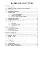
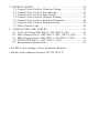
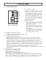
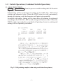
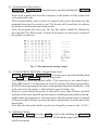

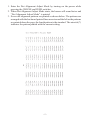
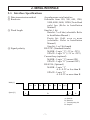
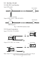
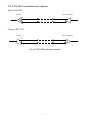

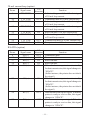
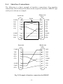
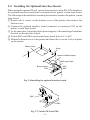

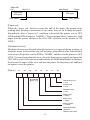
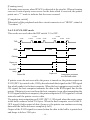
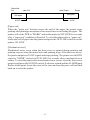
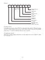
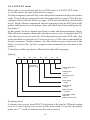

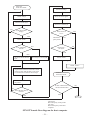
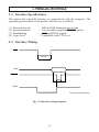
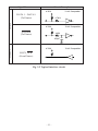
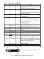

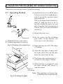
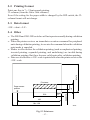

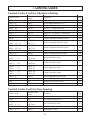


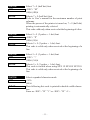


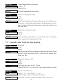
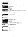
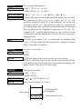
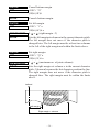


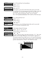
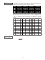

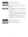

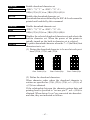


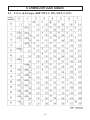
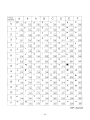

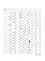

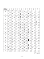
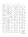
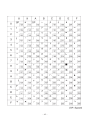
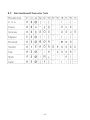


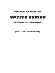
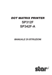

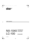


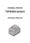

![User`s Manual DP8340II R SERIES [Serial]](http://vs1.manualzilla.com/store/data/005993516_1-f706d7540b19c5fecea062c6335f03cc-150x150.png)