1
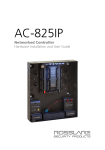
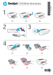
DeskJet 61xx Disassembly Procedures
TABLE OF CONTENTS
CASE PARTS...................................................................................................... 1
INPUT TRAY ASSEMBLY......................................................................................... 4
INPUT TRAY ASSEMBLY......................................................................................... 5
INPUT TRAY....................................................................................................... 6
PAPER MOTOR .................................................................................................. 7
CABLE HARNESS ................................................................................................ 9
WING FRAMES AND PAPER PUSHER ...................................................................... 10
POWER SUPPLY ................................................................................................ 11
MAIN PCA .................................................................................................... 13
BEAD FERRITE .................................................................................................. 14
PICK FEEDROLLER ASSEMBLY ................................................................................ 15
SPOT SENSOR ASSEMBLY (NOT APPLICABLE FOR 94X & 92X) ...................................... 16
ENCODER STRIP / CARRIAGE ROD ....................................................................... 17
CARRIAGE ASSEMBLY ........................................................................................ 18
CARRIAGE MOTOR ASSEMBLY / TURNAROUND ASSEMBLY ......................................... 20
INNER PAPER GUIDE / UPPER PAPER GUIDE ............................................................ 21
FEEDROLLER ASSEMBLY ...................................................................................... 23
PAPER DRIVE ................................................................................................... 24
LOWER PAPER GUIDE ........................................................................................ 25
CHASSIS ASSEMBLY .......................................................................................... 26
HUMIDITY INTERCONNECT PCA ........................................................................... 27
SERVICE STATION ............................................................................................. 28
DeskJet 61xx Disassembly Procedures
Case Parts
1. Remove the Rear Cleanout.
2. Lift the Access Door Assembly into a vertical position and pull upward to remove it.
3. Release the tab from underneath the unit and remove the Right Trim from the lower
right side of the unit.
4. Repeat step 3 for the Left Trim on the lower left side.
2
4
1
3
1
DeskJet 61xx Disassembly Procedures
5.
6.
7.
8.
9.
Remove two Side Case Screws from Top Case on top of the unit.
Using a screwdriver, gently pry up on the top tab of the Right Side Case.
Rotate the Right Side Case downward until the bottom tabs can be released.
Detach the cable from the Keypad.
Repeat steps 6 and 7 to remove the Left Side Case.
9
5
6
5
7
8
2
DeskJet 61xx Disassembly Procedures
10. Gently pry out the tabs on the lower left and lower right front of the Top Case,
then lift to remove.
11. Remove the Cover-Connector.
10
10
11
3
DeskJet 61xx Disassembly Procedures
Input Tray Assembly
1. Lift Output Tray Assembly, slide it forward and remove it from the Input Tray.
2. Locate the screw in the center-rear of the Input Tray and remove.
2
1
4
DeskJet 61xx Disassembly Procedures
Input Tray Assembly
3. Rotate unit upward so it rests on its back. Using a screwdriver, press through the
slot in the bottom of the unit to release the tab.
4. Gently pull upward on the Input Tray until the tabs have disengaged. Remove the
Input Tray.
4
4
3
5
DeskJet 61xx Disassembly Procedures
Input Tray
1. Slide Assembly Width Adjuster to far right.
2. Lift up top end of Width Adjuster so that it clears the lip of the tray.
3. Continue pushing the lifted assembly to the right to remove it from the tray.
1. Slide Length Adjuster towards the back of the tray until it is positioned halfway
between the front and back. Then remove Length Adjuster by lifting up its back
edge with a screwdriver while pushing it into the tray.
2. Continue to push until it clears the tray.
2
1
1
2
3
6
DeskJet 61xx Disassembly Procedures
Paper Motor
1.
2.
3.
4.
Disconnect Cable Harness from Paper Motor Drive and Paper Encoder PCA.
Remove Cable tie by compressing with needle-nose pliers.
Remove screw that holds Paper Motor Drive Assembly in place.
Release the bearing connecting Paper Motor Drive to Feedroller Assembly by
rotating it forward to unlatch it.
5. Lift Paper Motor Drive Assembly out of Chassis.
4
1
2
3
1
7
DeskJet 61xx Disassembly Procedures
1. Remove T-8 Taptite Screw, which secures Encoder PCA to assembly. Lift off
Encoder Guide and PCA.
2. Remove the two T-8 Screws holding the Paper Motor Assembly to the Motor
Bracket. Remove Paper Motor, and Idler Assembly.
3. Remove the Paper Belt.
4. Remove the Stealth Cluster Gear.
1
3
4
2
2
8
DeskJet 61xx Disassembly Procedures
Cable Harness
1.
2.
3.
4.
5.
Facing the back of the unit, free Cable Harness Assembly from right side of unit.
Disconnect cable from Carriage Motor and Main PCA.
Disconnect cable from Humidity PCA and Power Supply PCA.
Disconnect cable from Service Station Motor and Chassis.
Lift away Cable Harness Assembly.
Note: Handle connectors, rather than wires when disconnecting Cable Harness Assembly.
2
3
3
4
1
2
9
DeskJet 61xx Disassembly Procedures
Wing Frames and Paper Pusher
1. Release the two tabs that connect the Right Wingframe Assembly to the Chassis. Lift
Wingframe up and away.
2. Repeat steps for Left Wingframe Assembly.
3. Release tab and remove Pin Linkage Assembly that connects Pick Gear to Paper
Pusher Assembly by sliding it to the left.
4. Raise and lift out Paper Pusher.
1
3
2
4
10
DeskJet 61xx Disassembly Procedures
Power Supply
1. Rotate printer so that you are facing the back of the unit. Make sure that Power
Cord is disconnected at this time, because there may be dangerous voltage
applied. Use slip-joint or needle nose pliers to squeeze in plastic latches on either
side of the AC Connector to release cable from IEC Bracket.
2. Remove Power Supply PCA mounting screw.
3. Release tab connecting Housing to Backbone by pressing it in with a screwdriver
from the opposite side of the printer. Slide Housing to the right and lift out.
1
3
4
2
11
DeskJet 61xx Disassembly Procedures
1. Deflect tab on left side of Power Supply Housing.
2. Slide Power Supply PCA out of Housing.
2
1
12
DeskJet 61xx Disassembly Procedures
Main PCA
1. Detach Flex Head Driver Cable from Main PCA.
2. Remove two screws.
3. Lift out Main PCA Assembly.
1
3
2
2
13
DeskJet 61xx Disassembly Procedures
Bead Ferrite
1. Deflect tab, which holds Ferrite Clip in place.
2. Push Clip through to other side of unit and remove it.
3. Slide Ferrite off of Flex Head Driver Cable.
3
1
2
14
DeskJet 61xx Disassembly Procedures
Pick Feedroller Assembly
1. Press tabs on the top and bottom of Gear Gaurd to rock it out of the slot.
2. Remove Gear Gaurd.
3. Rotate Polar Bearing on right side forward to release. Rotate Polar Bearing on left
side forward by reaching through Chassis.
4. Lift out Pick Feedroller Assembly.
1
3
2
4
15
DeskJet 61xx Disassembly Procedures
Spot Sensor Assembly (not applicable for 94x & 92x)
1. Remove screw, which secures ESD Cover to Carriage Assembly.
2. Disconnect Spot Assembly Cable from Carriage PCA.
3. Unplug Spot Assembly Cable from Spot Sensor Assembly.
2
1
16
DeskJet 61xx Disassembly Procedures
Encoder Strip / Carriage Rod
1. Release Encoder Strip from catch on right end of Chassis.
2. Release from Encoder Spring on left end of Chassis and remove from Carriage
Assembly.
3. Remove two Special Screws, which hold the Carriage Rod to the Chassis.
4. Push Carriage Rod to right to release it from Backbone and lift it out.
5. Slide Carriage Rod out of Carriage Assembly.
6. Remove two Rod Mount Clips by rotating them 90 degrees and removing them
from Chassis.
7. The Encoder Spring will detach when Carriage Rod is removed. Pull spring away
from Chassis to release tabs.
3
2
7
4
3
6
6
5
1
17
DeskJet 61xx Disassembly Procedures
Carriage Assembly
1.
2.
3.
4.
Remove Belt Tension Spring to slip Carriage Belt off of Chassis.
Feed Flex Head Driver Cable through Backbone from back to front.
Flex cable to free tabs from Backbone.
Remove Carriage Assembly.
3
1
1
2
1
4
18
DeskJet 61xx Disassembly Procedures
1. Flex cable to remove from tabs on Carriage Assembly, then disconnect cable from
Carriage PCA and Slider. Flex Belt to remove it from Belt Attach Base (not shown).
2. Remove two screws connecting Slider to Carriage Assembly.
3. Remove three screws securing Belt Attach Assembly to Carriage Assembly and then
remove Belt Attach Assembly. Remove Belt Attach Tower from base. Remove Belt
Attach Beam from tower.
4. Carriage PCA will be released when Belt Attach Assembly is removed. Lift it away.
5. Remove ESD Springs from blades.
6. Remove Felt Retainer by prying it away with knife or sharp object. Remove Felt
Lubrication.
2
1
3
4
6
5
6
19
DeskJet 61xx Disassembly Procedures
Carriage Motor Assembly / Turnaround Assembly
1. Remove two screws, which secure Carriage Motor to Backbone.
2. Lift out Carriage Motor.
3. Slide Turnaround Assembly to the left while depressing tab on back, and lift out.
2
3
1
20
DeskJet 61xx Disassembly Procedures
Inner Paper Guide / Upper Paper Guide
1. Deflect tab on right side of Inner Paper Guide Assembly.
2. Slide assembly to the left and lift out.
3. Remove Pinch Springs, which secure Upper Paper Guide. Use caution when
handling the Upper Paper Guide, it breaks easily.
4. Pull Upper Paper Guide backwards until it drops free of Upper Paper Guide
Hanger and remove.
1
3
2
4
21
DeskJet 61xx Disassembly Procedures
1. Twist and lift out DOOPS Flag from Upper Paper Guide.
2. Rotate OOPS Flag downward, and lift out gently.
3. Slide Pinch Rollers sideways and lift them out of guide.
2
1
3
22
DeskJet 61xx Disassembly Procedures
Feedroller Assembly
1.
2.
3.
4.
5.
Grasp Caber Pin with needle-nose pliers and pull it forward until it snaps out.
Lift out Shifter Spring.
Release left Polar Bearing by rotating it forward.
Release right Polar Bearing using screwdriver.
Lift out Feedroller Assembly.
Snap Pivot away from Feedroller.
If necessary, remove Encoder Disk by peeling it off. Note: The Encoder Disk is a onetime use part. If removed it must be replaced.
1
3
4
2
5
23
DeskJet 61xx Disassembly Procedures
Paper Drive
1. Detach Lifter Spring from Chassis.
2. Deflect side latch and pull off Kick Cam.
3. Lift off Feedroller Idler Gear.
1
3
2
4. Rotate Pressure Plate Lever upwards to lift out.
5. Raise side tab on Separator Lifter, slide to the left, then lift out.
4
5
24
DeskJet 61xx Disassembly Procedures
Lower Paper Guide
1.
2.
3.
4.
5.
6.
7.
To free Lower Paper Guide, deflect latches on both sides with a screwdriver.
Tilt Lower Paper Guide backward and lift it out.
Lift out Separator Pad.
Lift out Separator Peg.
Remove Spring from Peg.
Lift out Rear Rollers and remove Rear Roller Springs.
Rotate Kicker and flex around tab to lift out.
3
6
4
5
6
1
2
7
25
DeskJet 61xx Disassembly Procedures
Chassis Assembly
1. Remove one screw on right side, and two screws on vertical face, which secures
the Backbone.
2. Tilt and lift away Backbone.
3. Remove four screws (black and silver taptite) on top of Backbone to remove Upper
Rail.
4. Remove two screws securing IEC Bracket and Cleanout Flag Stop from Upper
Paper Guide Hanger.
5. Lift and flex Upper Paper Guide Hanger to remove it from Chassis.
2
4
4
3
3
5
1
1
1
26
DeskJet 61xx Disassembly Procedures
Interconnect PCA
1. Remove screw, which connects Humidity Interconnect PCA to Chassis and remove
PCA.
1
27
DeskJet 61xx Disassembly Procedures
Service Station
1. Deflect tab on right and lift out Service Station.
2. Pry out Grounding Clip from the Chassis using a small screwdriver.
1
2
28