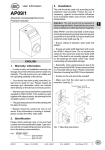
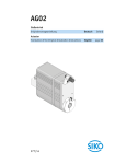
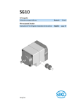
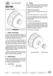
1
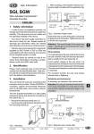
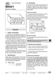
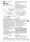
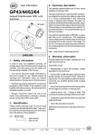
as sprayed water, dust, knocks, extreme temperatures.
User Information
Built-in housing EG
MA47
Push the display into the panel cut-out (1) until
the panel clips (2) hold the housing loosely.
Electronic Display
Press the lateral centering (3) slightly down and
push the housing into the cut-out (1) until the
panel clips (2) snap completely.
1
2
3
Fig. 1: Installation
ENGLISH
Bench housingTG
1. Safety information
Remove rubber plugs before fixing the housing.
• In order to carry out installation correctly, we
strongly recommend this document is read very
carefully. This will ensure your own safety and
the operating reliability of the device.
Attention ! The max. thread depth of 6.5 mm
must be absolutely respected!
• Your device has been quality controlled, tested and is ready for use. Please respect all
warnings and information which are marked
either directly on the device or in this document.
• Warranty can only be claimed for components
supplied by SIKO GmbH. If display MA47 is
used together with other products, the warranty
for the complete system is invalid.
• Repairs should be carried out only at our
works. If any information is missing or unclear,
please contact the SIKO sales staff.
2. Identification
Please check particular type of unit and type
number from the identification plate. Type number and the corresponding execution are indicated in the delivery documentation.
e.g. MA47-0023
4. Electrical connection
• Wiring must only be carried out with power off!
• Provide stranded wires with ferrules.
• Check all lines and connections before switching on the equipment.
Interference and distortion
All connections are protected against the effects
of interference. The location should be selected to ensure that no capacitive or inductive
interferences can affect the translation module or the connection lines! Suitable wiring
layout and choice of cable can minimise the
effects of interference (eg. interference caused
by switching power supplies, motors, cyclic
controls and contactors).
Necessary steps:
3. Installation
• Only screened cable should be used. Screen
should be connected to earth at both ends. Wire
cross section is to be at least 0,14 mm², max.
0,5 mm².
The unit should be used only according to the
protection level provided. Protect MA47, if necessary, against environmental influences such
• Wiring to the screen and the ground (0V) must
be secured to a good point and a large surface
area to allow minium impedance.
type number
type of unit
MA47
Datum 16.06.2000
Art.Nr. 76671
Z.Nr. 8664049
Änd.Stand 201/00
7
• The unit should be positioned well away from
cables with interference; if necessary a protective screen or metal housing must be provided. The running of wiring parallel to the mains
supply should be avoided.
• Contactor coils must be linked with spark
suppression.
• PE connection with 2.5 – 4 mm² via PE
terminal (fig. 2).
Power supply
is made via mains connection on rear of the
device. The correct supply voltage is indicated
in the delivery documentation:
Eg.:
24VDC ±20%
No.
1
2
3
4
5
6
7
8
9
10
Function Terminal Strip
+UB encoder supply
Signal A
Signal B
Index signal (I/O)
Earth screen / encoder supply
RFS signal for reference point source
Earth for reference point source
PE protective conductor
N/GND
L/+UB
4.2 Conn., Bench Top Casing TG
Reference switch
Power consumption
< 2 VA (without encoder)
4.1 Connection, Panel Mounting EG
Encoder
Power supply 230VAC/110VAC
24VDC ±20%
110 VAC -10% ... +6%
230 VAC -10% ... +6%
Power supply 24VDC ±20%
Proximity
switch
Fig. 4: Rear panel (type TG)
Encoder supply: Via 9 pole SUB-D socket on
rear of the unit (see fig. 4).
Fig. 2: Connection diagram (type EG)
Instead of mechanical reference value transmitter: proximity switch with NPN-output (ground
switching).
Fig. 3: Rear panel (type EG)
Pin no.
1
2
3
4
5
6
7
8
9
Connection of reference switch: via rear socket
and in accordence with the connection diagram
below (fig. 4).
Pin no.
1
2
3
8
MA47
Datum 16.06.2000
Function
+UB
A-Signal
B-Signal
I-Signal
GND
N.C.
N.C.
N.C.
N.C.
Art.Nr. 76671
Function
RFS
GND
+UB
Z.Nr. 8664049
Änd.Stand 201/00
5. Commissioning
The four membrane keys are used for operating
and programming display MA47.
Key functions
The keys’ functions depend upon the operating
mode (see description ‘Programming mode’ and
‘Input mode’). The keys are pressed singly or in
pairs (two together).
1
2
3
1. Programming mode: to program the display
at initial installation.
2. Input mode: to enter parameters/select
functions used during standard operation.
6. Programming mode
Display MA47 is pre-programmed to standard
values at our works. If the order defines customer-specific parameters, these will be pre-programmed at SIKO. For parameter modification
enter into programming mode. Normally programming is only necessary at initial installation. Parameters can be modified and checked at
any time. They are stored in a non-volatile
memory. Each parameter’s designation, function
and value range is shown on the following pages.
To enter into programming mode:
Press key
for at least 5 s
4
1. Programming
2. Select ‘value’
3. Select 'digit'
4. Store value
To leave programming mode:
Automatically, if no key has been pressed during
approx. 30 s or press key until the end of the
parameter list is reached.
Fig. 5: Key functions
To scroll through the parameters:
Press key
When switched on
When switched on and correctly connected:
• all LED segments are displayed
(for approx. 1.5 s)
• the software version ( eg.: 1.00) is displayed
Subsequently the specific parameters of the
machine can be programmed.
Operational modes
To change parameters:
Use keys
and
To store parameters:
Press key ; the parameters will scroll automatically.
There are two operational modes accessible via
the keyboard:
List of parameters
Fixed programming if
combined with MSK01, MSK02
Angle display Linear display
with MRI01
with MB320
Designation
Display
Value range
Display after one revolution:
Display divisor:
Encoder pulses per rev.:
_APU_
_Adl_
_Str_
0...59 999
1; 10; 100; 1000
0...59 999
Counting direction:
Type of index signal:
Positions after the comma:
Offset value:
Type of reference switch:
Referencevalue:
Increm. measurement enable:
Ref. value input enable:
Offset input enable:
Reset enable:
_drEh_
_Ind_
_dP_
_oFF_
_rFS_
_rEF_
rEL_F
rEF_F
oFF_F
SEt_F
I, E
I, O
0. ... 0.000
0.0
-199999...999999
Schl, oEFF, hAnd hAnd
-199 999...999 999
EIn, AUS (on, off)
EIn, AUS
EIn, AUS
EIn, AUS
EIn (on)
3600
100
1
1
512(number of poles x 8 25
eg.64poles x8=512)
MA47
Datum 16.06.2000
Art.Nr. 76671
Z.Nr. 8664049
0.0
hAnd
EIn (on)
Änd.Stand 201/00
9
Parameter description
Display
"Choice"
Designation/ description
_APU_
Display after 1 revolution: Value
by which the display increases /
decreases after 1 revolution of the
encoder. This value corresponds
eg. to the spindle pitch.
_Adl_
Display divisor: Divisor by which
the display accuracy is reduced compared to the measuring acuracy.
_rEF_
Reference value: Absolute datum
point (reference point) of the measuring system. This value is either set
after system calibration or zeroed
by activating the external reset input RFS.
rEL_F
Increm. measurement enable:
For programming section 2 (input
mode) via key and incremental measurement can be:
- released
- blocked
"EIn"
"AUS"
Example: Due to an odd ratio, the
measuring resolution is programmed to 1/1000 mm. The display,
however, needs a resolution of 1/10
mm only. -> The display divisor is
programmed to 100.
rEF_F
_Str_
Encoder pulses per revolution:
Increments of the connected encoder.
oFF_F
_drEh_
Counting direction: Counting direction of the system:
clockwise increasing value
counter-clockwise increasing values
"EIn"
"AUS"
Type of index signal: Reference
mark on the encoder disk; appears
only once per revolution; for defined
reference point marking.
Signal shape "O"; square signal
with positive logic
Signal shape "I": square signal with
inverted logic
"EIn"
"AUS"
"I"
"E"
_Ind_
"O"
"I"
_dP_
Positions after the comma:
Determination of the decimal point
position
"EIn"
"AUS"
SEt_F
Reference value input enable:
for programming section 2 (input
mode) reference value correction
via key
:
- released
- blocked
Offset input enable: for programming section 2 (input mode):
offset value correction via key
.
- released
- blocked
Reset enable: for programming section 2 (input mode) release reset via
key
:
- released
- blocked
7. Input mode
Incremental measurement function
Press keys
+ . to switch to incremental
measurement function.
The display is zeroed. The comma blinks.
_oFF_
Offset value: Determination of a
correction value (offset).
Press keys + again, to block incremental
measurement function and to restore display of
the absolute position value.
_rFS_
Type of reference switch: type of
reference value transmitter; can either be a mechanical contact or a
proximity switch.
Precondition: Menu point ‘Increm. measurement enable’ (rEL_F) in programming mode
must be programmed to "EIn".
"Schl"
Closing contact, which is normally
open; only active, if encoder has
index pulse.
Reference value correction
"oEFF"
"hAnd"
10
Opening contact, which is normally
closed; only active, if encoder has
index pulse.
Manual reset of the counter by activating input RFS (closing function).
MA47
Datum 16.06.2000
Press key (for at least 3 seconds) to activate
reference value correction.
The display shows alternatingly the current reference value and the symbol „rEF“.
Use the arrow keys to enter a new value.
Art.Nr. 76671
Z.Nr. 8664049
Änd.Stand 201/00
Press key
value.
to confirm and store the new
If key
has not been pressed and no value has
been entered during approx. 30 seconds, the
display returns to display mode without making
any value correction.
Precondition: Menu point (rEF_F) in programming mode must be programmed to "EIn" .
mounting of the reference point transmitter,
please adjust the incremental encoder in such a
way that the index pulse only appears when the
reference point switch is activated.
The contact of the reference switch must only
e active for less than one revolution of the
encoder (see fig. 7).
Fig. 6 shows the mounting principle.
one turn
Offset value correction
Press key
(for at least 3 seconds) to activate
offset value input.
The display shows alternatingly the current reference value and the symbol „oFF“.
signal A
signal B
type O
indexsignal
type I
Use the arrow keys to enter a new value.
Press key
to confirm and store the new value.
If key has not been pressed and no value has
been entered during approx. 30 seconds, MA47
returns automatically to display mode.
signal ref. point
transmitter
definitely
passive
definitely
active
definitely
passive
Fig. 6: Signal types for calibration
Precondition: Menu point (oFF_F) in programming mode must be programmed to "EIn" .
drive
driving spindle
Reset
Press key
to set the display to the programmed reference / offset value.
increm.
encoder
ref. point
transmitter
Any programmed ‘incremental dimension’ (which
is signaled by the blinking comma) will be taken
into account.
8. Manual calibration
For setting the display to the reference / offset
value either
• press key
incremental display MA07
Fig. 7: Calibration setup
or
• briefly activate (by connecting to GND) input
RFS (terminal no. 6).
Information concerning the setting of the
reference point:
Precondition: Menu point_rFS_ in programming
mode must have been programmed to "Hand" .
The display can thus be zeroed, if the reference
value was previously programmed to 0.
Move the spindle exactly to the position which
corresponds to the reference value programmed
as per chapter 8. The mecanically mounted
reference point transmitter must now be definitely active (see fig. 5).
9. Automatic calibration
The encoder can be turned without causing any
movement of the driving spindle, if you untighten
the clamping ring or coupling. You can now
search the index signal of the encoder (voltage
change) by using for example a voltmeter and
carry out the adjustment to the reference point.
Electronic linking of the signals from a reference
point transmitter (eg. cam switch or limit switch)
with the index pulse (index marker) of the connected encoder will calibrate the measuring
display, ie. a start position is defined. During
MA47
Datum 16.06.2000
Art.Nr. 76671
Z.Nr. 8664049
Änd.Stand 201/00
11
When the index and reference point transmitter
signals are positioned as described in fig. 5, the
clamping ring and the coupling of the incremental encoder are retightened.
10. Trouble shooting
Error states are recognized and shown in the
display:
Message: full
Description: display overrun
Elimination: control parameters and adjust them
if necessary; calibrate display
Message: blinking display of value 00000
Description: operating voltage too low
Elimination: check voltage supply
Message: blinking decimal point.
Description: MA47 cannot be calibrated to the
programmed offset/reference value.
Elimination: MA47 is in ‘incremental measurement’ mode; press key to change to absolute
measurement.
SIKO
GmbH
DR.-ING. G. WANDRES
Postanschrift / Postal address:
Postfach 1106
D-79195 Kirchzarten
Werk / Factory:
Weihermattenweg 2
D-79256 Buchenbach
Telefon / Phone 0 76 61 / 3 94 - 0
Telefax / Fax
0 76 61 / 3 94 - 388
Internet www.siko.de
12
MA47
Datum 16.06.2000
Art.Nr. 76671
Z.Nr. 8664049
Änd.Stand 201/00