1
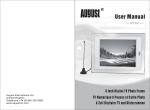
LCD display units
User manual
Entertainment series
Notice
Before use the screens ,please read this user manual carefully!
Please do not disassembly screens. If screens can not work, please contact local
distributor or us!
Menu
user manual
2
Noticing of safety points
1. AG series Splice crystal display product
1.1 Products series
3
1.2 Serials introduction
3
1.3 LCD display unit signal interface
4
1.4 LCD display unit install orde
5
1.5 Size and technical parameters
6
2.Install Explanation
2.1 serials LCD wall circuit connection
7
2.2 LCD wall install way
8
3.IR remote control use introduction
3.1 IR remote control receiver/ controller
3.2.1000, 5000 serials IR remote control operate introduction
9
10
4.LCD wall control management system explanation
4.1 LCD wall control management system summarize
4.2.1 LCD wall control software startup and settings
11
11
4.2. 2 LCD display unit settings
12
4. 3 LCD display unit control
13
4. 4 LCD matrix signal swift
14
4. 5 Template settings
16
5. Screen Display Menu
OSD
4.1 Image
18
4.2 Sound
19
4.3 System
20
4.4 Advanced settings
21
4.5 Geometry
22
4.6 Picture in picture
23
4.7 TV
23
6. Fault Maintenance
25
7.Packing list
26
8.Warranty
27
Noticing of safety points
user manual
1 Do read the manual before using.
2 Keep the manual well
3 Notice the safety warning
4 Operation in wet situation is not allowed.
5 Keeping away from chemical gas and medicine, do not wash the outer or the inner of the product
with acute volatile solvent or cleanser, such as gasoline, acetone.
6 Prevent the entering of liquid or other goods, warning if any liquid falls into the inner of products
through the interstice.
7 There will be heat in operation, so make sure no blocking at the outlet. Do install the machine
as the manual.
8 A perfect measure of connecting the earth is required, or a confusion of the system may occure,
which would lead to the unstable operation of the system, even cause the damage of the equipment.
9 Do not install the machine near the power, such as the radiator, heat reservoir, furnace. or others.
10 Do cut off the power before pulling out or re-connecting any component( except supporting hot
plug ones)
11 Please pull out the plug before lighting or long time's shelving.
12 Please consult to the professional maintenance man in case that an urgent repair is needed.
13 The following requires the maintenance man to handle
a damage of the cable or the plug
any material or liquid enters the inner of the machine
suffered rain
a deviant working or a sharp altering of the performance happens
it drops abruptly or the damage of the crust
¾¯ ¸æ
warning
Electric shock,do not open
To reduce the risk of electric shock,do not remove the lid
(or back cover).There is no user repair parts internal.Please
delegate professional maintenance staff to maintenance.
. Introductions of series Splice crystal display product
user manual
Our LCD Display Unit adopted the most advanced industrial LCD panel in
the world, which owns the feature of high brightness and contrast, small splicing sew,
real and nature picture, wide function, simple to function, stable operation, long life,
convenient maintenance, low price,etc.
40 inch and 46 inch high d efinition LCD monitor display unit, build in
embedded FPGA hardware controlling system to ensure the stable operation,
powerful functions, complex video providing, YpbPr, S-VIDEO, VGA, DVI, HDMI.etc
input interface, which meets the real-time processing needs of high definition signal
1920*1080. LCD is a complete device, requires no accessories, simple installation
as blocking by shape to realise an immediate using, protected by the outer
harden-glass, convenient transportation and installations, multi-units can combine
into a full screen discretionarily (such as 2x2, 4x4, 2x4,M x N).
1.1 Products series
AG 1000 series: Single screen display(repet display 1 signal),M*N all screens
display. It can be run without matrix. Applicable to hotel, entertainment areas,
large-scale performance venues, enterprise, public place and advertisement video
wall of super market and plaza.
AG-5000 series: support single screen display( we can input M x N channels
signal and display non-repeatly), any combination display, M x N full screen display
function, without conjugate using of matrix system. Which mainly applies for
amusement place, public place and meeting room.
LCD display
AGT independent
develop most advanced
digital processing technique----Dynamict super resolution technique.
user manual
1.2 Main screen and deputy screens
A unit of 1000 series as main screen which afford signal input and disposal,
other screens as deputy screens. The interface of main screen is different of deputy
screens.
1.3 LCD units signal interface
Each LCD Display unit back side mid-down part has one interface panel, use for
connect all kinds input and output signal.
AG-1000 main screen interface see as below
1000 deputy screens
interface see as right:
AG-5000 interface see as below:
(1)AC 220V alternating current 220V power input
(9)VGA In PC VGA signal input
(2)RS232 In SATA control signal input
(10)Av Complex Video/Audio output
(3)RS232 OUT SATA control signal output
(11)Av1 Complex Video/Audio input
(4)DVI In DVI figure signal input
(12)S VIDEO S port video signal input
(5)DVI OUT DVI figure signal output
(13)Av2 Complex video/audio 2 input
(6)REMOTE In IR control signal input
(14)Y/Pb/Pr high definition chromatic
(7)LED work indicating light, Red for pause,
green for work.
(8)HDMI high definition digital signal input
aberration signal
(15)VGA:VGA Audio output
(16)VGA audio input
(17)Tv VGA Audio output
1.Introduction of series splice crystal display products
user manual
1.4 LCD display units install order
For convenient LCD manager software recognise and manager different LCD
unit, System ordain each LCD display unit corresponding to one address code
(ID code). ID code follow the above rules: from LCD frontispiece, up-left is 1,from
left to right, up to down sequence. For example:
2x2 Splice coding as following
1
2
3
4
3x3 Splice coding as following
1
2
3
4
5
6
7
8
9
4x4 Splice coding as following
And so no
1
2
3
4
5
6
7
8
9
10
11
12
13
14
15
16
1. series LCD products instruction
User manual
1.5 LCD Screen splice unit technical parameters
Model
AG-5046
Dimension
1046 (W)x596.2 (H)x95(D)mm
1920x1080P
Resolution
Activation display area
1018.08(H)x572.67(V)
97%
Color saturation
Brightness
700cd/m2
Contrast
3000:1
Refresh Frequency
Display color
120Hz
10 Bit 10 billion color
View angle
178 degreen
Splice sew
18mm
Input interface Complex Video, chromatic aberration signal , S-VIDEO, VGA, DVI, HDMI
Signal format
Control interface
NTSC, PAL, 480P, 576P, 720P, 1080I,1080P
IR controller and Rs232
Operation temperature
0-40
Operation humidity
15-85%
Power supply
AC220V
Average power
250W
22KG
Weight
Installation way
Wall, embedded, ground cabinet, suspend, TV cabinet
-6-
2.Install explanation
user manual
2.1 series LCD circuit connection
1000 series LCD wall just can display a video signal at the same time,
it can display this signal on all units, multi-units or any combination of units,
connection methods is as below:
5000 series LCD wall can individual display video signals, it can display on
random combined units, all units, multi- units, connection way is as below:
2.Install explanation
user manual
Multi-channel Video signal source apart connect into corresponding matrix input,
matrix output according to splice wall ID code connect into corresponding splice wall
display unit video input port.
Control mainframe RS232 control circuit connect into matrix, matrix RS232 output
through display unit control signal interface (RS2232IN/US232OUI), connect all
display units one by one.
All the liquid crystal display unit concatenate DVI port one by one, the last screen
DVI output were followed back to the main screen of the DVI input.
2.2 LCD wall install way
According to use situation request and locale practice circs, can adopt TV cabinet wall,
embedded, cabinet, stand..etc install ways
1)TV cabinet
3)Console mounting
2)Wall and embedded mounting
3.IR remote control introduction
user manual
3.1 IR remote control receiver/controller
Using the remote control can easily adjust screen display menu. Before use the remote control
must connect main screen interface with REMOTE IN.
3.1 .1Controller keys functions introduction: (from up to down)
[Power]:On/stand by key
[SOURCE]: Siganl source select key
[Image mode]: image scene select key
[Sound mode]: sound mode select key
[P.SIZE]: Image size select FULL,16:9 or 4:3
[DISPLAY]: Image state display
[Timing] Sleep/timing off key
[Numer1~9]:Channel direct select key
MENU
call-out/exist menu key
[VOL+/-]: Adjust volume key
[CH+/-]: Channel adjust key
[AUTO]: Auto image amend key
[HDMI] HDMI signal input fast key
[VGA] VGA signal input fast key
[AV] AV signal input fast key
[S VIDEO]:S video signal input fast key
[YPr/Pb] YPr/Pb signal input fast key
[TV] TV signal input fast key
[Full screen]
[Each screen]
3.IR remote control use explanation
user manual
3.2. AG-5000 IR remote control use explanation
1)Plug in SLCD units.
2)Power on SLCD units.
3)Press [VOL+/-]: Adjust volume key
4)Press [CH+/-]: Channel adjust key
5)Full screen display Press function key 1then
press number1-9 in 2.5 seconds you can choose
1-9 screen's signal display on full screens
6)Single display press function key 2/EXIT key, then
press number 0-9 in 2.5 seconds ,a single screen can
display it's input signal,0 means each screen's input signal
7)Single screen display public digital matrix signal press function key 3/MUTE key
then press number 0-9 in 2.5 seconds, a single screen can display public digital
matrix signal, press 0 each screen display public digital matrix signal
8)Single screen menu operation if you need to operate the menu of a screen of video
wall,for example, No.1 screen,make No.1 screen image display to full screens, then
press menu key,you will see images unified change
then make each screen display
you will see only No.1 screen parameter change.
9) signal cross-screen display: for example, No. 1, the signal should be sent to the
2-screen display, according to the following steps:
a first screen of screen No. 1, according to a function key, then press the number keys
1, the No. 1 off-screen signal to the public digital matrix.
b by function 2, press the number key 0 key, to return all the screen shows the respective
signals.
c by function 3, press the number keys 2, this time on the 1st screen signal will be displayed
on the 2nd screen.
10)Press full screen key all screens display communion signal
11)Press sub-screen key each screen display communion signal
Public digital matrix: AG-5000 series in each display unit built-in digital video matrix,
each display unit connected with the DVI signal lines, when the stitching unit with mosaic
image or signal when the cross-screen display, built-in public digital matrix that is spliced
image or cross-screen display of the map sent to all of the DVI signal line. At this point in
the DVI cable the signal shall be public digital matrix signals.
4.LCD control management software explanation
user manual
4.1 Summarize
LCD installed completed, connect kinds of external equipments and signal circuit, can
work normally after debugging.
Before switch-on, please check equipments, power supply and signal circuit connection
whether normal, after that, switch on external equipments (such as matrix, PC.) and signal
source, then connect with LCD power supply, then LCD can start to work.
4.2 AG-1000 series LCD manager software
AG
1000 sereis LCD manager software conjugate with1000 series LCD
corresponding software, this software easy for understand, convenient and quick, it is the
tools for conjugate with LCD.
Software running environment:
Operating system: Windows 98/2000/NT/XP
Over 32M storing memory
Over 10G hard disk space
CD-ROM
At least one SATA interface
The installation of managing software
Put the disk into the PC driver, execute: AG-5000.exe, the system would auto install the
software.
4.2.1 the startup and setting of the software
1) turn off the power of the display units, connect the communication lines into each display unit
2)on the PC screen, double click the icon of LCD wall control management system
entertainment edition start the software, then
pop-up a window to input the password,
after entering 1 the operation window opens.
4.LCD control management system explanation
user manual
4.2.2 LCD units rank settings
Setting LCD number of column and row: software default display unit number of column
and row state is 3x3, it means LCD column No. is 3, Row No. is 3, if the fact number is
unconformity with default number, like splice wall is 4 columns, 3 rows, can go to operate
software: System Setting---- Screen Setting to set columns and rows After finished setting then
click switch off key, then the system will remind you restart admin software, press confirm and
restart admin software interface
Yes
No
Restart control software you will see window below
Notice When you setting the lines and rows of LCD units, please connect RS232
communication cables to each unit it will work when you plug in power supply.
4.LCD control management system explanation
user manual
4.3 Splice Unit Control
Unit Control option card can setting splice wall each display unit's work state and running
parameters, as photo
4.3.1 Unit control function introduction:
[Unit Add]: In corresponding splice unit single screen's ID select, for convenient operate the
individual display unit, select 00 means all select.
[Setting SATA]: select control mainframe and splice matrix connected SATA port, only select
the correct control software then can control splice matrix and splice display unit normally,
mostly default SATA will be COM1.
[Power]: simulate circuit switch, can cut off LCD display unit's power and come to pause state.
[Freeze] freeze displaying images
[Signal select] press this key corresponding LCD unit display signal select menu
[Full screen display] press this key whole LCD unit display public number matrix's image
[Sub-screen display] Press this key each LCD display unit independent input image
[Single unit back] press this key each LCD display unit will return itself signal input signal
[Public signal] press this key
for selected display unit signal send digital matrix public channel.
[Menu] simulate remote control menu key with UP/DOWN/LEFT/RIGHT key
can operate display unit
[UP],[DOWN],[LEFT],[RIGHT]:menu move assistant key
[AV]AV signal input shortcut key
[VGA]VGA signal input shortcut key
[TV] TV input shortcut key
[YPr/Pb]YPr/Pb signal input shortcut key
[S-VIDEO]S video signal input shortcut key
[HDMI]HDMI signal input shortcut key
[Frame covor]start the function of frame shielding while clicking the key
the key please drag and drop once
after press
4.LCD control management system explanation
user manual
4.4 Matrix signal swift and splice control operation
AG-1000 series is an example AG-5000 series operation is the same
4.4.1 Single screen display
On software interface, select destine unit,move RGB signal menu to destine unit.
Then you will see destine image signal on the screen.(Blue screen when no signal
input,same as below)
For example:Display video signal 1 on No.6 screen
Left-click No.6 screen,the color will become dark;move mouse to video signal 1,
press left move it to NO.6 screen,you will seen video signal 1 on No.6 screen.
4.4.2 Multi-screens display
On software interface,Select several adjacent units, move RGB signal menu to
destine unit.Then you will see destine image signal on the screen.You will see destine
image display on those units
For example: display RGB signal on number 6 7
Left-click number 6
RGB signal
7
display grey
10
11 units
6
7
10
10
11 units
11 units become blue;move mouse to
,press left move it to number 6
7
10
11then loosen the
mouse,you will see RGB signal on number 6,7,10,11 units(multi-display)
4.LCD control management system explanation
user manual
4.4.3 All screens display
On software interface,select all the screnns,the color become black, move to destine
unit in VGA signal menu.Then you will see destine image signal on the screen,press
left and moving it to all the units then leave the mouse
For example: display VGA signal on all screens
Left-click and move through all units,units color becomes black,then move mouse
to destine unit in RGB signal menu, press left and moving it to all the units then leave
the mouse,you will see VGA on all screens
4.LCD control management system explanation
user manual
4.5 Template ettings
Template function means user define splicing screens display and system provide
time sequence display ways, template display flexible random and individual.
On CONTROL MANAGEMENT SYSTEM---SYSTEM SEETINGS--TEMPLATE SETTING, then you will see template setting window, see as below:
4.5.1 Function explanation
User can random define screens display
User can add and delete template display mode
Control management system provides 12 time sequence programs
Each program display time can set on the right bottom of PROGRAM TIME SEQUENCE
4.5.2 User-defined kaleidoscope time sequence
Press TEMPLATE ADD key, you will see below template add window,
4.LCD control management system explanation
user manual
On screen display area,choose the display units which you are willing to show images,,
such as user need number 1 and 2 screens to splice display,lecf-click number 1 and 2 units
which will become dark,then press right button drag them to time sequence area 1.
See picture as below,
4.5.3 Series provided template time sequence
Control software bring 6 kinds of template display time sequence, move mouse
to one template and press right button to drag it to time sequence area 10,see
below picture,
After drag and drop,user can mark out template introduction at TEMPLATE
INTRODUCTION,see picture as below.Click confirm key to finish template settings.
Invoke template function ,press left button of mouse and drag TEMPLATE
of control management system signal source to display area. So LCD units will display
TEMPLATE mode.
5.Screen display menu
OSD
user manual
5.1 Image
1.Select Menu ,you will see Image menu.As shown,
OSD adjustment interface in Menu of PC/HDMI mode
P
C
50
50
CONTRAST
BRIGHTNESS
COLOR MODE
SCALE
AUTO
PICTURE MODE
£º
SEL
NORMAL
PERSONAL
£º
ADJ
MENU
£º
EXIT
OSD adjustment interface in Menu of AV,S-VIDEO,YPBPR mode
PICTURE
50
50
50
50
50
CONTRAST
BRIGHTNESS
HUE
SATURATION
SHARPNESS
COLOR TEMP
SCALE
PICTURE MODE
3D NR
£º
S EL
NORMAL
FULL
PERSONAL
MID
£º
ADJ
MENU
£º
EXIT
5.Screen display menu
OSD
user manual
Contrast ratio:Adjust the sharp effects of image, the dark of black part get richer and white
get lighten
Brightness:The dark of image get lighten,just as add white in the color
Hue: Cold and warm color adjustment in NTSC format
Saturation: Increase or decrease color
Definition: Increase or decrease definition
Color temprature:Standard,personal setting,warm color,cold color,S-RGB(only PC)
Image mode:Standard,movement,softness,personal setting to adapt the programs.
3D noise reduce:Digital 3D noise reduction
2.Select Up or Down , high-light display images menu items
3.Select Left or Right to increase or decrease the parametre of selected items.
4.Complete setting,keep selecting Menu until menu exit
5.2 Sound
1.Select Menu of control software enter the main menu,select Left&Right until see Sound
interface.As following:
SOUND
EQUALIZER
BALANCE
SOUND MODE
TREBLE
AVC
LOUDNESS
SUPERBASS
£º
SEL
50
MUSIC
OFF
OFF
OFF
OFF
£º
ADJ
MENU
£º
EXIT
5.Screen display menu
OSD
User manual
Balancer: Increase or decrease frequency response of frequency bands.
Balance: Dual-speaker system,adjust volume balance
Audio:Music/news/standard/personal setting
Treble:Increase or decrease the treble of screen
Auto Volumn control:ON/OFF
Sound Mode:ON/OFF Grade 1,2,3
Mega Bass: Increase bass effect.Grade 1,2,3,4
2.Select Up/ Down, high-light display Sound menu items:Balancer/Balance/Audio/Treble/
Auto volume control/sound mode/mega bass
3.Press Left/Down to increase or decrease the parameters of selected item.
3.Complete settings, keep selecting Menu until menu exit
5.3 System
1.Select Menu of control software enter the main menu,select Left&Right until see Sound
window .As following:
SYSTEM
OSD-LANGUAGE
OSD H-POSITION
OSD V-POSITION
OSD DURATION
OSD HALFTONE
INFORMATION
MEM-RECALL
£º
SEL
ENGLISH
50
50
100
100
£º
ADJ
MENU
£º
EXIT
5.Screen display menu
OSD
user manual
Menu language:OSD language menu. English,Chinese,Franch,Italian,Spanish,German,
Dutch,Russian, Portuguese,Korean and Arabic.
Menu Horizontal position:Adjust left and right position of OSD interface
Menu virtical position:Adjust the up and down position of OSD interface
Menu display time: OSD menu residence time
Menu diaphaneity: Adjust menu display diaphaneity
System Initialization: Select it will recovery to factory settings
2.Select Up/ Down, high-light display System menu items
3.Select Left or Right to increase or decrease the parametre of selected items.
4.Complete setting,keep selecting Menu until menu exit
5.4 Advanced settings
1.Select Menu of control software enter the main menu,select Left&Right until see
Adanced Settings interface.As following:
MENU
5.Screen display menu
OSD
user manual
Automatic shutdown: 15 min,30min,45min,60 min automatic shutdown selectable.
9Image
9Image program search
Blue screen: Blue screen display when no signal input
2. Select Up or Down , high-light display images menu items
3.Select Left or Right to increase or decrease the parameter of selected items.
4.Complete setting, keep selecting Menu until menu exit
5.5 Geometry
Notice: only PC and HDMI have Geometry adjustment interface
1.Select Menu of control software,display the screen menu .Select Left/Right to Geometry.
As shown:
GEOMETRY
100
100
100
100
H-POSITION
V-POSITION
CLOCK
PHASE
£º
S EL
£º
ADJ
MENU
£º
EXIT
Horizontal position: Image adjust horizontally
Vertical position: Image adjust vertically
Clock: VGA clock adjustment
Phase: VGA phase adjustment
2. Select Up or Down , high-light display images menu items
3.Select Left or Right to increase or decrease the parameter of selected items.
4.Complete setting, keep selecting Menu until menu exit
5.Screen display menu
OSD
user manual
5.6 Picture in picture
1.Select Menu,you will see menu on screen.Select Right to PIP menu,as shown:
PIP
MULTI WINDOW
SUB SOURCE
SIZE
BORDER COLOR
SOUND SOURCE
SWAP
PIP POSITION
SEL
OFF
AV
LARGE
BLACK
MAIN
LEET UP
ADJ
MENU
EXIT
Multi-image: ON/OFF PIP function
Deputy image:Select PIP signal:HD,VGA,Video1,Video2
Size:Adjust PIP windows size
Edge color:Black/Blue
Sound channel:Select primary and secondary audio signal source
Switch:Switch main or deputy picture signal
Sub picture position: Left-up/Left-down/Right-up/Right-down
2. Select Up or Down , high-light display images menu items
3.Select Left or Right to increase or decrease the parameter of selected items.
4.Complete setting,keep selecting Menu until menu exit
5.7 TV
1. Select Menu,you will see menu on screen.Select Right to TV menu,as shown:
5.Screen display menu
OSD
user manual
TV
AUTO SCAN
MTS
CHANNEL EDIT
FINETUNING
MANUAL SEARCH
COLOR SYSTEM
SOUND SYSTEM
AREA FREQ
FREQ FROM
SEL
MONO
AUTO
DK
TAI WAN
CATV
ADJ
MENU
EXIT
Auto program searching: Auto search programs and auto save
Stereo:Switch between stereo and mono
Channel editor: Naming channel
Manual tuning:Manual tuning to best effect
Manual searching:Manual search program
Color system:Switch among PAL,SECAM and NTSC
Audio format:Switch among B/G,D/K and I
Frequency dot region: Video region
Frequency dot source: Video program source
1. Select Down , high-light display Channel or Auto Searching,select Right to set
2.Complete setting,keep selecting Manu until menu exit
Tips for watching antenna or cable TV
Please connet antenna or cable TV with LCD screen
When you plug in LCD screen,run auto save function,search broadcast or cable channels.
If you do not do it,LCD screen maybe unable to operate
When you run Auto save function,check auto run result,select channel +/- to select channels.
5.Fault maintain
User manual
Fault performance
Unable to power on
Disposal methods
Check power cables, ensure two ends both plug in socket; Ensure
use safe and reliable power supply
No signal
Check signal cables, ensure link rational; Ensure power is turn on;
Ensure input options match input signal
Remote control can not
work
Ensure battery without
weeping; Ensure remote control is in the remote distance; Ensure
remote control point to screen remote window; Ensure there are no
obstructions between the remote control and screen remote
window
Flash point, or stripes
appear on screen
Ensure keep away from interference such as car, high voltage power
supply and neon
Image color or quality
degradation
Ensure all channel settings(brighteness,contrast,color) adjust
reasonable; more information of video settings, please refer to OSD
introductions
Image position or size incorrect
Ensure image position and size adjust to reasonable range
Image or color incorrect
Ensure signal cables link reasonable; If connect with PC, you can
change the resolution of PC to get correct image. Output signal
differences will influence image
Display alarm
Ensure input signal cables fix reasonable; choose correct in
put signal
Screen can not display
entirely
Address code incorrect; Signal interface incorrect
Blue screen
Signal cables break off; No signal input
- 25 -
7.Packing list
user manual
7.Warranty
User manual
The Comsumer shall have no coverage or benefits under this
wattranty if any of the following conditions are applicabel:
Warranty Explaination:
1.Company product sold out within one year, belong to product-self quality problem, can repair by
free charges by this card (Non-human damage), Lifetime Maintenance.
2.Due to incorrect operate or other reasons as well as malfunction product, can repair by this card,
free maintainance but components costs.
3.when need repairs, please hand on this card and invoice copy file to us or local maintain
department.
Aparted the machine shell privately, tear up label, should charge maintian fee and component
fee as ordain
.4..Do not accept the malfunction's product due to modify or add other functions' product.
The Consumer shall have no coverage or benefits under this warranty if any of the following
conditions are applicable:
1.Periodic check, maintenance ,repair or change accessory due to normal abrasion.
2.Fallen down, extrusion, damp as well as other tampering.
3.Flood,fire,lightening strike as well as other natural hazards or factors beyond control
4.Products repaired by non-authorized repair centres.
5.All warranty information are subject to change according to relevant rules.
£¨
Please fill in and send back£©
User information
Contact
Address
Tel
Fax
Mobile
Zip code
Email
Model
serial Number
Purchase date:
W a r r a n t y r e c o r d s
Fault description
Disposal methods
- 27-
Warranty date Maintenance man