1
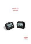
SMARTYCAM
User Manual
SmartyCam
User Manual
Release 1.02
Dear Customer,
SmartyCam, the new camcorder with data overlay, descends from the great AIM
experience in developing data acquisition systems, mainly for motorsports applications.
SmartyCam allows to review racing performances on PC or TV, merging crystal clear
images with graphical data coming from integrated GPS and three-axial accelerometer, as
well as from ECU (Engine Control Unit from here onward ECU) or from an AIM logger: that
is why SmartyCam can be used in any situation, on any sort of vehicle.
Acquired data can be overlaid to frames in a great variety of formats, configurable by the
user. On a Micro SD card hours of movies/sounds/data can be saved: ratio is
approximately 1 Giga = 1 hour.
It is recommended to periodically check www.smartycam.com for software and/or firmware
updates or – recommended option – subscribe the www.smartycam.com newsletter to
receive all updates in real time.
Warning: this user manual is regularly updated. All new versions can be found on
www.smartycam.com. Please make sure your manual is the latest version
available: the issue number of each manual is reported on the top of the page.
2
www.smartycam.com
SmartyCam
User Manual
Release 1.02
INDEX
INTRODUCTION ............................................................................................................................................... 4 Chapter 1 – SmartyCam: kit and optional items ........................................................................................... 5 1.1 – SmartyCam kits ............................................................................................................................................................................ 5 1.2 – ECU bridge kits ............................................................................................................................................................................. 5 1.3 – SmartyCam optional items: cables and external microphone ................................................................................................. 6 Chapter 2 – Data sampled by SmartyCam stand alone/slave ..................................................................... 7 Chapter 3 – SmartyCam connections ............................................................................................................ 8 3.1 – Connecting SmartyCam stand alone .......................................................................................................................................... 8 3.2 – Connecting SmartyCam in Slave expansion mode with ECU Bridge ..................................................................................... 9 3.3 – SmartyCam in Slave expansion mode with AIM loggers ........................................................................................................ 10 Chapter 4 – SmartyCam battery charging ................................................................................................... 11 4.1 – Battery charging via USB .......................................................................................................................................................... 11 4.2 – Battery charging via connector ................................................................................................................................................ 11 Chapter 5 – SmartyCam configuration ........................................................................................................ 12 Chapter 6 – How to use SmartyCam ............................................................................................................ 13 6.1 – “Battery and Memory Status” field ........................................................................................................................................... 13 6.2 – How to switch SmartyCam on/off ............................................................................................................................................. 14 6.3 – SmartyCam Menu ....................................................................................................................................................................... 14 6.3.1 – “SETTINGS” option .............................................................................................................................................................. 15 6.3.1.1 – Accelerometer calibration: “ACCEL CALIBR” option ........................................................................................................ 15 6.4 – How to record videos ................................................................................................................................................................. 16 6.4.1 –Manual recording .................................................................................................................................................................. 16 6.4.2 –Automatic recording .............................................................................................................................................................. 17 6.5 – SmartyCam recording support ................................................................................................................................................. 17 Chapter 7– Downloading data and viewing SmartyCam videos ............................................................... 18 7.1 – Downloading data....................................................................................................................................................................... 18 7.2 – Viewing SmartyCam videos ...................................................................................................................................................... 18 7.2.1 – Viewing SmartyCam videos on the PC ................................................................................................................................ 18 7.2.2 – Viewing SmartyCam videos on the TV ................................................................................................................................ 18 Chapter 8 – SmartyCam Maintenance ......................................................................................................... 18 Appendix “A” – Technical specifications ................................................................................................... 19 Appendix “B” – SmartyCam Pinout ............................................................................................................. 20 Appendix “C” – SmartyCam cables Pinout ................................................................................................ 21 Appendix “D” – ECU Bridge Pinout ............................................................................................................. 23 Appendix “E” – SmartyCam with external power ...................................................................................... 25 Appendix “F” – Connection scheme with AIM loggers ............................................................................. 26 F.1 – SmartyCam – ECU Bridge connection scheme ....................................................................................................................... 26 F.2 – SmartyCam – MXL connection scheme ................................................................................................................................... 28 F.3 – SmartyCam – EVO3 connection scheme ................................................................................................................................. 31 F.4 – SmartyCam – EVO4 connection scheme ................................................................................................................................. 34 F.5 – SmartyCam – MyChron4 connection scheme ......................................................................................................................... 37 3
www.smartycam.com
SmartyCam
User Manual
Release 1.02
0
INTRODUCTION
SmartyCam features three different working modes.
Stand alone: for non-motorsport applications or for motorsport applications in case there
is no Engine Control Unit (ECU) nor AIM data acquisition system (from here onward:
logger).
Slave connected to the vehicle ECU: for motorsport applications to sample data out
coming from the ECU but with no need or possibility of sampling data coming from
additional sensors. In this case an ECU Bridge is required.
Slave connected to an AIM logger: for motorsport applications in case a detailed
analysis of performances is needed, using also additional sensors. In this case the ECU
bridge is not required because connection to the vehicle ECU is made using the AIM
logger.
4
www.smartycam.com
SmartyCam
User Manual
Release 1.02
1
Chapter 1 – SmartyCam: kit and optional items
SmartyCam package includes a complete kit that permits standard usage: in this manual
some optional items are also shown, which can be useful in particular situations.
24
1.1 – SmartyCam kits
Stand alone kit: X90SMYC00
1 – SmartyCam (metallic grey or glossy red);
1 – power supplier;
1 – adapter
1 – power cable;
1 – USB cable for data download and battery charge;
1 – 4 Giga Micro SD;
1 – user manual;
1 – CD containing SmartyConf software and USB driver.
Slave kit with ECU Bridge or AIM logger (EVO3 Pro/Pista, EVO4, MXL Strada/Pista
/Pro05, MyChron4):
• X90SMYCEC2 with 2m power cable + CAN.
• X90SMYCEC4 with 4m power cable + CAN.
1 – SmartyCam (grey metallic or glossy red);
1 – power supplier;
1 – adapter
1 – 2m or 4m power cable + CAN (for AIM logger/ECU Bridge connection);
1 – USB cable for data download and battery charge;
1 – 4 Giga Micro SD;
1 – user manual
1 – CD containing SmartyConf + Race Studio 2 software and USB drivers.
Warning: to use SmartyCam in slave working mode it is necessary to buy an ECU
Bridge or to have the appropriate AIM logger.
14
1.2 – ECU bridge kits
There are two available ECU Bridges, required to connect SmartyCam to the vehicle
ECU. Their part number changes according to the communication protocol they are
equipped with.
• ECU Bridge with CAN/RS232 communication protocol: X90BGGPI2R
• ECU Bridge with CAN/K Line communication protocol: X90BGGPI2K
Each ECU Bridge kit includes:
1 – ECU Bridge
1 – USB cable.
5
www.smartycam.com
SmartyCam
User Manual
Release 1.02
25
1.3 – SmartyCam optional items: cables and external microphone
SmartyCam optional tools can be connected to it using the 7 pins connector placed on the
camcorder rear and shown here below.
SmartyCam kit includes a power cable used to charge the battery: in order to connect it to
an external power supply or to an additional external microphone it is necessary to buy
optional cables.
The external power source can be useful to stand alone users to avoid SmartyCam
internal battery consumption. In case of slave use, on the contrary, connection to the
vehicle battery is compulsory: the cable is included in the kit (the optional cable is
necessary only to connect an additional external microphone).
Use of an additional external microphone can be useful, for instance, to the driver that
wants to communicate with its staff.
•
•
Power cable with CAN and microphone: this cable allows SmartyCam to connect to
an external 12V power source, to enable an external microphone, automatically
mixed with the internal stock one, and to connect via CAN to an AIM logger or an
ECU Bridge.
External microphone: additional microphone automatically mixed to the stock one. It
plugs directly in the 7 pins connector placed on the camcorder rear.
6
www.smartycam.com
SmartyCam
User Manual
Release 1.02
2
Chapter 2 – Data sampled by SmartyCam stand alone/slave
As said before, according to its working mode, SmartyCam provides different information.
In Stand Alone mode, SmartyCam gets data coming from integrated GPS and three-axial
accelerometer:
•
•
•
•
•
•
position;
GPS speed;
acceleration
lap time;
distance;
track mapping.
In connection to an external data acquisition system, like an AIM logger (EVO3 Pro/Pista,
EVO4, MXL Strada/Pista/Pro05 or MyChron4) or an ECU (via ECU bridge), SmartyCam
can visualize in graphical overlay:
•
•
•
all info acquired in Stand Alone version;
all info coming from the vehicle Engine Control Unit connected to AIM logger;
all info acquired by AIM logger (RPM, more speeds, LCU-ONE Lambda value,
engaged gear, temperatures, pressures, etc…).
WARNING: for further useful information check:
www.aim-sportline.com website download area to know which ECU’s are supported
by AIM logger and their connection/communication protocols;
Race Studio Configuration user manual to understand how to configure AIM
loggers, ECU Bridge included;
each AIM logger user manual.
7
www.smartycam.com
SmartyCam
User Manual
Release 1.02
3
Chapter 3 – SmartyCam connections
The alternative SmartyCam modes (Stand Alone or Slave Expansion) require different
connection procedures.
15
3.1 – Connecting SmartyCam stand alone
SmartyCam stand alone can be connected in different ways:
•
connection to the external power: use the 7-pins connector highlighted in the image
above and connect the power cables to a 12 Volts power source i.e. the vehicle
battery.
•
connection to the external microphone: the external microphone plugs directly in the
7 pins connector highlighted in the image here above.
•
connection to optional cables and external microphone: use the 7-pins connector
highlighted in the image here above and connect the power cables to an external 12
Volts power source.
Warning: if SmartyCam is connected to an external power not connected to the
vehicle master switch nor to the sampled GPS speed and auto power off has not
been set (paragraph 6.1), it is necessary to manually power on/off SmartyCam when
switching on/off the vehicle.
8
www.smartycam.com
SmartyCam
User Manual
Release 1.02
26
3.2 – Connecting SmartyCam in Slave expansion mode with ECU Bridge
In order to receive the info provided by the vehicle ECU without any additional logger,
SmartyCam must be used in Slave expansion mode and connected via CAN to an ECU
Bridge, using the 7-pins connector placed on the product rear. Today ECU Bridges are
available for CAN, RS232 e K Line communication protocols.
Please refer to appendix “B” and “D” to know SmartyCam and ECU Bridge pinout.
Warning: please refer to Race Studio Configuration user manual for more info
about ECU Bridge configuration, and to www.aim-sportline.com documentation
download area for more info about ECU supported by AIM systems and their
communication/connection protocols.
9
www.smartycam.com
SmartyCam
User Manual
Release 1.02
27
3.3 – SmartyCam in Slave expansion mode with AIM loggers
SmartyCam can visualize even data sampled by an AIM logger (EVO3 Pro/Pista, EVO4,
MXL Strada/Pista/Pro05 or MyChron4) and by the vehicle ECU. In this case it is necessary
to connect SmartyCam via CAN to the logger, using the power and CAN cable to be
inserted into the 7-pins connector placed on the camcorder rear.
Please refer to appendix “B” of this manual to know SmartyCam pinout and to the
user manuals of each AIM logger to know its pinout.
The image below shows i.e. SmartyCam connected to an EVO4.
10
www.smartycam.com
SmartyCam
User Manual
Release 1.02
4
Chapter 4 – SmartyCam battery charging
SmartyCam is supplied with a 2000mAh 3.7 Volt rechargeable lithium battery. It can be
charged using both the 7-pins connector and the USB port highlighted in the image below
on the right. Connect SmartyCam to an external power source.
The battery charge status is shown in any SmartyCam page. Below on the left the related
field is shown.
16
4.1 – Battery charging via USB
SmartyCam battery charging via USB has two possible options.
Socket charge (recommended):
•
connect SmartyCam (switched off) to the power supplier using the cable included in
the kit: it has to be plugged in the 7-pins connector placed in the product rear;
•
insert the power supplier plug in the socket.
In case of PC charge via USB (not recommended): connect SmartyCam (powered off)
directly to the PC on, using the cable included in the kit. It is recommended not to use a
USB hub. It is also recommended to use exclusively a 2.0 USB port.
Please do not connect SmartyCam to the PC unless having installed SmartyConf
software.
Warning: not all Personal computers USB ports provide enough power to charge
SmartyCam and anyway, due to the power supply limitation of the PC, battery
charging is longer. That is why socket charge is recommended.
17
4.2 – Battery charging via connector
SmartyCam battery can be charged using the external power cable connected to the rear
connector of the camcorder.
11
www.smartycam.com
SmartyCam
User Manual
Release 1.02
5
Chapter 5 – SmartyCam configuration
In order to configure SmartyCam data overlay (selection of data to visualize, their layout
and position) SmartyConf software – expressly developed by AIM – needs to be used.
This software is provided with a CD included in SmartyCam kits and can be downloaded
from www.smartycam.com, download area.
To configure SmartyCam connect it to the PC:
WARNING: it is strictly necessary to install SmartyConf software before
SmartyCam connection to the PC
(v. SmartyConf user manual downloadable from www.smartycam.com)
• set the preferred data overlay;
• transmit the new configuration to SmartyCam;
• switch the camera off and on again
• SmartyCam will automatically set that configuration.
Refer to SmartyConf user manual for information about data overlay configuration.
SmartyCam slave needs its master (AIM logger or ECU Bridge) configuration through
Race Studio 2 software, included in both the slave kits with 2m and 4m power cable).
Please note: SmartyCam configuration is independent from its master
configuration: it is thereby unnecessary to modify it changing SmartyCam master.
12
www.smartycam.com
SmartyCam
User Manual
Release 1.02
6
Chapter 6 – How to use SmartyCam
SmartyCam is managed using the three buttons placed above the display: 1,2 and 3 in
the image below.
The menu on the display shows the functions related to each button, close to the button
itself.
All SmartyCam pages are made up of three parts:
•
•
•
18
top of page menu functions are shown;
in the middle of the page specific info are shown;
in the lower part the “Battery and Memory Status” field is shown.
6.1 – “Battery and Memory Status” field
“Battery and memory Status” field constantly shows the level of battery charge and the
remaining memory available for recording. In “On line” and “GPS status” the GPS signal
strength is shown, too.
The above indicator refers to the available memory and shows in black the used part and
in grey the available one. When available memory is lower than 300 kB the black part
becomes red. The number right of the bar is the available space in Giga (in the image
below SmartyCam works with a 4 Giga Micro SD).
The below indicator shows the battery charge status. The number on the right switches
between battery tension – SmartyCam working range is between 4.1 and 3.5 V – and
percentage of available battery (image here below on the right).
13
www.smartycam.com
SmartyCam
User Manual
Release 1.02
19
6.2 – How to switch SmartyCam on/off
SmartyCam can be switched on in two ways:
•
•
pressing “2” button, or
connecting the external power cable to SmartyCam: as soon as the camcorder
receives the 12 V power, will automatically switch on.
SmartyCam can be switched off in the following ways:
•
•
•
28
pressing “2” button any time “Off” option is available
pressing “2” button for 10 seconds. This forced option is to be used JUST in case of
camcorder lock, as it can lead to cancellation of some of the latest recorded
data/images
automatic switch-off: if still for 15 minutes, SmartyCam will switch automatically off.
NOTE: this function can be disabled in the “SETTINGS” menu (“AUTO
POWEROFF” function).
6.3 – SmartyCam Menu
When SmartyCam is switched on, three options appear:
•
Rec
recording process will start (v. paragraph 6.4)
•
Off
the camera will switch off (v. paragraph 6.2)
•
Menu
several options appear
Clicking “Menu” a new page will appear, showing (in loop) the following options:
PLAYER
It allows to manage recorded videos: “Down” scrolls the list of
videos and “Sel” selects the desired video. Once selected, it is
possible to view it (“Play”) or cancel it (“Del”)
GPS STATUS
It shows the connected satellites and the signal strength (good or
weak)
SETTINGS
It allows to set several key parameters (v. paragraph 6.3.1)
LAP MNGMT
It shows the geographic coordinates of the place where the
camcorder is positioned. It permits to fix the starting point of GPS
lap times (selecting “Fix”): once a point is fixed, every time
SmartyCam will pass there, a laptime will be registered.
DASH
Info page: it shows the data acquired by the camera (if stand
alone) or by the external acquisition system, ECU or logger (if
slave)
On the top of this page, the functions “Down” (to scroll the options), “Exit” (to go back to
the previous page) and “Sel” (to select the desired option) appear.
14
www.smartycam.com
SmartyCam
User Manual
Release 1.02
34
6.3.1 – “SETTINGS” option
As anticipated, by clicking “SETTINGS” several options appear:
LANGUAGE
It permits to choose the desired language
DISPLAY T.out
Enabling this function it is possible to avoid useless
battery consumption, switching off the display after 30”.
Registration will not be stopped.
TIME SETTING
It allows to choose the time zone and to enable/disable
daylight saving time.
CONFIG
It allows to choose a pre-defined overlay configuration
among a list of available options (i.e. USA kart or Euro
kart, car, airplane, etc.)
INFO
Info page where some camcorder technical data are
shown.
AUD/VID SET
It allows to set some Audio/Video options useful to
maximize recording quality in case of: SmartyCam use
onboard or on vehicle roof, zoom or not, with/without
external microphone
ACCEL CALIBR
This option allows to calibrate the 3D accelerometer, in
order to get correct acceleration data and fine tune video
frames. (paragraph 6.3.1.1.)
AUTO REC
This option allows to choose manual vs. automatic
recording: in this case recording process will start as
soon as some threshold parameters are reached
(paragraph 6.4.2).
AUTO POWEROFF
It allows to disable automatic power-off of the camcorder
after 15 minutes inactivity (paragraph 6.2)
6.3.1.1 – Accelerometer calibration: “ACCEL CALIBR” option
Great attention must be given to accelerometer calibration procedure, because it impacts
either on acceleration data accuracy and on correct frame choice.
In order to set calibration parameters, place the camcorder on a plane surface, switch it
on, select “ACCEL CALIBR” option and then click on “Calibr”.
In order to keep correct calibration parameters even once SmartyCam is installed on the
vehicle, the following steps must be followed:
• Install the camera
• Select “ACCEL CALIBR”
• The 2 coordinate axis appear: correct calibration point can be immediately fixed
clicking “Calibr”
• It is also possible – clicking “Prev” – to preview the frame on the display: when this
frame is ok, click “Calibr” to fix calibration point.
15
www.smartycam.com
SmartyCam
User Manual
Release 1.02
20
6.4 – How to record videos
It is possible to record images both manually and automatically
35
6.4.1 –Manual recording
Immediately after switching SmartyCam on, the display shows the following page:
The keyboard (“A”) allows to:
•
•
•
start recording, pressing “Rec”;
switch SmartyCam off, pressing “Off”;
enter “Menu Status”, pressing “Menu”.
The mid of the page (“B”) is divided in two parts:
• above (“B1”) the real time image frame is visible;
• below (“B2”) info related to recording process are shown: “Pause” registration and
“Record” (recording time is shown).
To start recording, press “Rec”: SmartyCam will show this page:
The keyboard (“A”) allows to:
• stop recording pressing “Stop”: SmartyCam comes back to “Online Status”;
• switch SmartyCam off, pressing “Off”;
WARNING: NEVER remove the Micro SD until SmartyCam is completely switched
off
The lower part (“C”) is “Battery and Memory Status”.
•
•
When SmartyCam is recording a red indicator appears on the left .
After a pre-defined time of inactivity the display will switch off (see paragraph 6.3.1).
16
www.smartycam.com
SmartyCam
User Manual
Release 1.02
36
6.4.2 –Automatic recording
It is possible to set the automatic recording option (“AUTO REC”). This permits to
start/stop recording without manual input. That’s how it happens:
• In slave mode (SmartyCam connected to an AIM logger): the logger transmits a
start/stop recording input to Smartycam, as soon as it detects RPM’s or a speed
higher/lower than 10 km/h.
• In stand alone mode: recording starts/stops automatically when speed is more/less
than 10 km/h or acceleration exceeds 0.2 G.
21
6.5 – SmartyCam recording support
SmartyCam kits include a 4 Giga Micro SD but it can support up to 16 Giga.
Warning: use only High Capacity Micro SD like this:
Warning: never remove the micro SD from SmartyCam while recording. To remove
the micro SD stop recording and wait for 20 seconds or start power off procedure
and wait until SmartyCam has completely shut down (paragraph 6.1).
17
www.smartycam.com
SmartyCam
User Manual
Release 1.02
7
22
Chapter 7– Downloading data and viewing SmartyCam videos
7.1 – Downloading data
SmartyCam allows to download data either via USB (connecting the camcorder to the PC
using the cable provided with the kit) either through the micro SD placed in the
SmartyCam rear, which will have to be inserted in the PC USB port. It is recommended to
use exclusively a 2.0 USB port.
Warning: when inserting/removing the Micro SD please make sure the flip on the
rear is firmly closed.
23
7.2 – Viewing SmartyCam videos
Videos recorded on SmartyCam micro SD are .avi files with H.264 codec and can be
seen both on PC and on TV.
37
7.2.1 – Viewing SmartyCam videos on the PC
To see the videos on a PC display just remove the micro SD from SmartyCam switched
off, place it in the reader (or in a portable one connected to the PC like any USB pen drive)
and manage it as an USB peripheral.
Videos are in “Video” folder.
It is reminded that – to see videos recorded with SmartyCam on the PC – a software
compatible with H.264 format is needed.
Were such software not available, it is recommended to use “VLC Media Player”,
which can be downloaded from www.videolan.org/vlc/.
38
7.2.2 – Viewing SmartyCam videos on the TV
To see SmartyCam videos on the TV ensure that the DVD reader is compatible with ”avi.”
Files with H.264 codec: otherwise the video file needs to be converted in a format
compatible with the available reader.
For example it is possible to transform the .avi file in a DVD, using a software like “Nero”
(version 8 or higher), Roxio or similar softwares.
In case the reader had no Micro SD input, it is necessary to copy the video on a DVD (or
even a CD) with a simple burning software.
Chapter 8 – SmartyCam Maintenance
SmartyCam does not require any particular maintenance.
Warning: it is strongly recommended not to open the camcorder.
It is recommended to periodically check www.smartycam.com for software and/or firmware
updates or – recommended option – subscribe the www.smartycam.com newsletter to
receive all updates in real time.
18
www.smartycam.com
SmartyCam
User Manual
Release 1.02
8
Appendix “A” – Technical specifications
SmartyCam measures (in mm)
Accelerometer
three-axial
Internal battery
2.000 mAh 3.7 Volt lithium – rechargeable
Battery charge
via socket/via CAN: 700 mAh max
via PC: 450 mAh max
Battery autonomy
until 3 hours with acquisition
Temperature working range
-20°C/+60°C
Display size
128*160 pixel
Weight
210g battery included
Memory
4 Giga (up to 16 Giga supported)
Memory consumption
1 hour recording = about 1 Giga
19
www.smartycam.com
SmartyCam
User Manual
Release 1.02
9
N. rev. / Rev. N.
Appendix “B” – SmartyCam Pinout
Descrizione / Description
Firma / Signature
Data / Date
Contr. da / Ckd. by
SMARTYCAM PINOUT
7
1
6
5
4
2
3
CAN Bus Binder Pinout
Contact insertion view
1
2
3
4
5
6
7
Q.tà/Q.ty
Rif. / Ref.
Progettato da / Designed by
CAN+
GND
+Vb
CANVbext
GND
Mic2+
Material / Material
Contr. da / Ckd. by
N. articolo / Item N.
Approvato da / Approved by
Nome file / File name
Data / Date
L.I.
Scala / Scale
12/01/2009
Titolo / Title
Pinout SmartyCam
N. disegno / Drawing N.
Rev. / Rev.
Foglio / Sheet
1 of 1
Racing Data Power
20
www.smartycam.com
SmartyCam
User Manual
Release 1.02
10
Appendix “C” – SmartyCam cables Pinout
N.rev. / Rev. N. Descrizione / Description
Rif. / Ref.
Q.tà / Q.ty
Progettato da / Designed by
Materiale / Material
Contr. da / Ckd. by
Contr. da / Ckd. by
Function
nc
GND
nc
nc
+Vbext
nc
nc
1
2
3
4
5
6
7
Nero
Rosso
GND
+Vbext
Firma / Sign
Pin
Fonction
Cable colour
Not terminated cables pinout
7 pins Binder 712
male connector pinout
Contact insertion view
7 pins Binder 712
male connector
External power for SmartyCam pinout
Not terminated cables
RED
BLACK
Data / date
N. articolo / Item N.
Approvato da / Approved by
Nome file / File name
Data / Date
Scala / Scale
D.B.
Titolo / Title
Cavo alimentazione esterna per SmartyCam
N. disegno / Drawing N.
Racing Data Power
04.556.03
Rev. / Rev.
Foglio / Sheet
1 of 1
21
www.smartycam.com
SmartyCam
User Manual
Release 1.02
N.rev. / Rev. N. Descrizione / Description
Rif. / Ref.
Q.tà / Q.ty
Progettato da / Designed by
GND
+Vbext
Contr. da / Ckd. by
1
2
3
4
5
CAN+
nc
+Vb
CANnc
Black
Red
CAN+
GND
+Vb
CANVbext
nc
nc
1
2
3
4
5
6
7
Function
Pin
Function
Function
Colore cavo
Not terminated cables pinout
Materiale / Material
Contr. da / Ckd. by
Firma / Sign
Pin
7 pins
Binder 712 male
connector
7 pins Binder 712
male connector pinout
Contact insertion view
5 pins Binder 712
male connector pinout
Contact insertion view
RED
Not terminated cables
BLACK
CAN and power adapter cable for SmartyCam pinout
5 pins
Binder 712
male connector
Data / date
N. articolo / Item N.
Approvato da / Approved by
Nome file / File name
Data / Date
Scala / Scale
D.B.
Titolo / Title
Cavo alimentazione e CAN per SmartyCam
N. disegno / Drawing N.
Racing Data Power
04.566.01 (cable lenght 4m)
04.566.02 (cable lenght 2m)
Rev. / Rev.
Foglio / Sheet
1 of 1
22
www.smartycam.com
SmartyCam
User Manual
Release 1.02
Appendix “D” – ECU Bridge Pinout
N.rev. / Rev. N. Descrizione / Description
Rif. / Ref.
Q.tà / Q.ty
Progettato da / Designed by
Firma / Sign
Contr. da / Ckd. by
CAN1+
CAN1GND
RS232TX
RS232RX
GND
+Vbext
Black
Red
Fonction
Materiale / Material
Contr. da / Ckd. by
CAN+
GND
+Vb
CANVbext
1
2
3
4
5
Fonction
Pin
5 pins Binder 712
female connector
5 pins Binder 712
female connector pinout
contact insertion view
ECU BRIDGE
Cable colour
Not terminated cables pinout
RED
BLACK
BLACK
BLUE
WHITE
NOT TERMINATED CABLES
Pinout of ECU Bridge for SmartyCam: CAN/RS232 protocol
WHITE
BLUE
Data / date
White
Blue
Black
Blue
White
11
N. articolo / Item N.
Approvato da / Approved by
Nome file / File name
Data / Date
Scala / Scale
L.I.
Titolo / Title
Collegamento cavi SmartyCam -ECU Bridge protocollo CAN/RS232
N. disegno / Drawing N.
Racing Data Power
Rev. / Rev.
Foglio / Sheet
1 of 1
23
www.smartycam.com
SmartyCam
User Manual
Release 1.02
Descrizione / Description
True hall
1000 Ohm resistor
(inside the connector)
Contr. da / Ckd. by
SMD 120 Ohm resistor
(inside the connector)
16
CAN 14
CAN +
6
15
L line
1
GND
K line
7
Firma / Signature
CAN -
+ Vbatt
4
5
3
Material / Material
Contr. da / Ckd. by
5 pins Binder
female connector
solder termination view
+ Vb
4
3
GND
2
1
2
5
1
CAN +
CAN K&L line
ECU Bridge
5 pins female
Binder connector
Progettato da / Designed by
5
K Line & L line ECU Bridge pinout
Q.tà/Q.ty
Rif. / Ref.
9
8
16 pins OBD2 connector pinout
solder termination view
+Vb Ext
Red cable
GND
Black cable
Data / Date
OBD2
connector
N. rev. / Rev. N.
N. articolo / Item N.
Approvato da / Approved by
Nome file / File name
Data / Date
Scala / Scale
L.I.
Titolo / Title
Pinout ECU Bridge CAN linea K &L
N. disegno / Drawing N.
Rev. / Rev.
Foglio / Sheet
1 of 1
Racing Data Power
24
www.smartycam.com
SmartyCam
User Manual
Release 1.02
Appendix “E” – SmartyCam with external power
Descrizione / Description
Firma / Signature
Contr. da / Ckd. by
SmartyCam
Data / Date
+
-
SmartyCam with external power
N. rev. / Rev. N.
EXTERNAL
BATTERY
12
Rif. / Ref.
Q.tà/Q.ty
Progettato da / Designed by
Material / Material
Contr. da / Ckd. by
N. articolo / Item N.
Approvato da / Approved by
Titolo / Title
Nome file / File name
Data / Date
Scala / Scale
SmartyCam con alimentazione esterna
N. disegno / Drawing N.
Racing Data Power
Rev. / Rev.
Foglio / Sheet
1 of 1
25
www.smartycam.com
SmartyCam
User Manual
Release 1.02
13
F.1 – SmartyCam – ECU Bridge connection scheme
Descrizione / Description
Firma / Signature
Data / Date
Contr. da / Ckd. by
SmartyCam
N. rev. / Rev. N.
+
ECU
EXTERNAL
BATTERY
-
ECU BRIDGE
SmartyCam - ECU Bridge connection
29
Appendix “F” – Connection scheme with AIM loggers
Rif. / Ref.
Q.tà/Q.ty
Progettato da / Designed by
Material / Material
Contr. da / Ckd. by
N. articolo / Item N.
Approvato da / Approved by
Titolo / Title
Nome file / File name
Data / Date
Scala / Scale
Collegamento SmartyCam -ECU Bridge
N. disegno / Drawing N.
Rev. / Rev.
Foglio / Sheet
1 of1
Racing Data Power
26
www.smartycam.com
SmartyCam
User Manual
Release 1.02
Descrizione / Description
Data / Date
Firma / Signature
Contr. da / Ckd. by
-
+
ECU
EXTERNAL
BATTERY
ECU Bridge
Data Hub
SmartyCam
SmartyCam-ECU Bridge connection with Data Hub
N. rev. / Rev. N.
Rif. / Ref.
Q.tà/Q.ty
Progettato da / Designed by
Material / Material
Contr. da / Ckd. by
N. articolo / Item N.
Approvato da / Approved by
Titolo / Title
Nome file / File name
Data / Date
Scala / Scale
Collegamento SmartyCam + ECU bridge con Data Hub
N. disegno / Drawing N.
Rev. / Rev.
Foglio / Sheet
1 of 1
Racing Data Power
27
www.smartycam.com
SmartyCam
User Manual
Release 1.02
F.2 – SmartyCam – MXL connection scheme
Descrizione / Description
Data / Date
Rif. / Ref.
Q.tà/Q.ty
Progettato da / Designed by
Firma / Signature
Contr. da / Ckd. by
-
+
MXL Strada/Pista
EXTERNAL
BATTERY
SmartyCam
N. rev. / Rev. N.
SmartyCam - MXL Strada/Pista connection
30
Material / Material
Contr. da / Ckd. by
N. articolo / Item N.
Approvato da / Approved by
Titolo / Title
Nome file / File name
Data / Date
Scala / Scale
Collegamento MXL Strada/Pista - Smarty Cam
N. disegno / Drawing N.
Racing Data Power
Rev. / Rev.
Foglio / Sheet
1 di 1
28
www.smartycam.com
SmartyCam
User Manual
Release 1.02
Descrizione / Description
Rif. / Ref.
Q.tà/Q.ty
Progettato da / Designed by
Data / Date
Firma / Signature
Contr. da / Ckd. by
MXL Strada/Pista
BATTERY
+EXTERNAL-
Data Hub
SmartyCam
SmartyCam - MXL Strada/Pista connection with Data Hub
N. rev. / Rev. N.
Material / Material
Contr. da / Ckd. by
N. articolo / Item N.
Approvato da / Approved by
Titolo / Title
Nome file / File name
Data / Date
Scala / Scale
Collegamento MXL Pista/Strada - SmartyCam con Data Hub
N. disegno / Drawing N.
Racing Data Power
Rev. / Rev.
Foglio / Sheet
1 of 1
29
www.smartycam.com
SmartyCam
User Manual
Release 1.02
Descrizione / Description
Rif. / Ref.
Q.tà/Q.ty
Progettato da / Designed by
Data / Date
Firma / Signature
Contr. da / Ckd. by
MXL Pro05
+
-
EXTERNAL
BATTERY
Data Hub
SmartyCam
SmartyCam - MXLPro05 connection with Data Hub
N. rev. / Rev. N.
Material / Material
Contr. da / Ckd. by
N. articolo / Item N.
Approvato da / Approved by
Titolo / Title
Nome file / File name
Data / Date
Scala / Scale
Collegmento MXL Pro05 - SmartyCam con Data Hub
N. disegno / Drawing N.
Racing Data Power
Rev. / Rev.
Foglio / Sheet
1 di 1
30
www.smartycam.com
SmartyCam
User Manual
Release 1.02
F.3 – SmartyCam – EVO3 connection scheme
Descrizione / Description
Data / Date
Q.tà/Q.ty
Progettato da / Designed by
Contr. da / Ckd. by
Contr. da / Ckd. by
EXTERNAL
BATTERY
Material / Material
+
EVO3 Pista
Rif. / Ref.
Firma / Signature
SmartyCam
N. rev. / Rev. N.
EVO3 Pista - SmartyCam connection
31
N. articolo / Item N.
Approvato da / Approved by
Titolo / Title
Nome file / File name
Data / Date
Scala / Scale
Collegamento EVO3 Pista - SmartyCam
N. disegno / Drawing N.
Rev. / Rev.
Foglio / Sheet
1 of 1
Racing Data Power
31
www.smartycam.com
SmartyCam
User Manual
Release 1.02
Descrizione / Description
Rif. / Ref.
Q.tà/Q.ty
Progettato da / Designed by
Data / Date
Firma / Signature
Contr. da / Ckd. by
+
EXTERNAL
BATTERY
-
EVO3 Pista
Data Hub
SmartyCam
EVO3 Pista - SmartyCam connection with Data Hub
N. rev. / Rev. N.
Material / Material
Contr. da / Ckd. by
N. articolo / Item N.
Approvato da / Approved by
Titolo / Title
Nome file / File name
Data / Date
Scala / Scale
Collegamento EVO3 Pista - SmartyCam con Data Hub
N. disegno / Drawing N.
Rev. / Rev.
Foglio / Sheet
1 of 1
Racing Data Power
32
www.smartycam.com
SmartyCam
User Manual
Release 1.02
Descrizione / Description
Data / Date
Rif. / Ref.
Q.tà/Q.ty
Progettato da / Designed by
Firma / Signature
Contr. da / Ckd. by
Material / Material
Contr. da / Ckd. by
EVO3 Pro
+
EXTERNAL
BATTERY
-
Data Hub
SmartyCam
SmartyCam - EVO3 Pro connection with Data Hub
N. rev. / Rev. N.
N. articolo / Item N.
Approvato da / Approved by
Titolo / Title
Nome file / File name
Data / Date
Scala / Scale
Collegamento EVO3Pro-SmartyCam+DataHub
N. disegno / Drawing N.
Rev. / Rev.
Foglio / Sheet
1 of 1
Racing Data Power
33
www.smartycam.com
SmartyCam
User Manual
Release 1.02
F.4 – SmartyCam – EVO4 connection scheme
Descrizione / Description
Firma / Signature
Data / Date
Contr. da / Ckd. by
EVO4
+
EXTERNAL
BATTERY
SmartyCam
N. rev. / Rev. N.
SmartyCam - EVO4 connection
32
Rif. / Ref.
Q.tà/Q.ty
Progettato da / Designed by
Material / Material
Contr. da / Ckd. by
N. articolo / Item N.
Approvato da / Approved by
Titolo / Title
Nome file / File name
Data / Date
Scala / Scale
EVO4 - SmartyCam connection
N. disegno / Drawing N.
Rev. / Rev.
Foglio / Sheet
1 of 1
Racing Data Power
34
www.smartycam.com
SmartyCam
User Manual
Release 1.02
Descrizione / Description
Rif. / Ref.
Q.tà/Q.ty
Progettato da / Designed by
Firma / Signature
Contr. da / Ckd. by
SmartyCam
Data / Date
EVO4
Data Hub
+
EXTERNAL
BATTERY
-
SmartyCam - EVO4 connection with Data Hub
N. rev. / Rev. N.
Material / Material
Contr. da / Ckd. by
N. articolo / Item N.
Approvato da / Approved by
Titolo / Title
Nome file / File name
Data / Date
Scala / Scale
Collegamento EVO4 - SmartyCam con Data Hub
N. disegno / Drawing N.
Rev. / Rev.
Foglio / Sheet
1 of 1
Racing Data Power
35
www.smartycam.com
SmartyCam
User Manual
Release 1.02
Descrizione / Description
Rif. / Ref.
Q.tà/Q.ty
Progettato da / Designed by
Data / Date
Firma / Signature
Contr. da / Ckd. by
Data Hub
Lambda
Controller
EVO4
BATTERY
+EXTERNAL-
Lambda probe
SmartyCam
SmartyCam - EVO4 connection with Data Hub and Lambda Controller
N. rev. / Rev. N.
Material / Material
Contr. da / Ckd. by
N. articolo / Item N.
Approvato da / Approved by
Nome file / File name
Data / Date
Scala / Scale
Titolo / Title
Collegamento EVO4 - SmartyCam con Data Hub e Lambda Controller
N. disegno / Drawing N.
Rev. / Rev.
Foglio / Sheet
1 of 1
Racing Data Power
36
www.smartycam.com
SmartyCam
User Manual
Release 1.02
F.5 – SmartyCam – MyChron4 connection scheme
Descrizione / Description
Data / Date
Rif. / Ref.
Q.tà/Q.ty
Progettato da / Designed by
Firma / Signature
Contr. da / Ckd. by
SmartyCam
N. rev. / Rev. N.
MyChron4
SmartyCam - MyChron4 connection
33
Material / Material
Contr. da / Ckd. by
N. articolo / Item N.
Approvato da / Approved by
Titolo / Title
Nome file / File name
Data / Date
Scala / Scale
Collegamento MyChron 4 - SmartyCam
N. disegno / Drawing N.
Rev. / Rev.
Foglio / Sheet
1 of 1
Racing Data Power
37
www.smartycam.com
SmartyCam
User Manual
Release 1.02
Descrizione / Description
Rif. / Ref.
Q.tà/Q.ty
Progettato da / Designed by
Firma / Signature
Data / Date
Contr. da / Ckd. by
BATTERY
+
EXTERNAL
MyChron4
Data Hub
Data key
SmartyCam
SmartyCam - MyChron4 connection with Data Hub and Data Key
N. rev. / Rev. N.
Material / Material
Contr. da / Ckd. by
N. articolo / Item N.
Approvato da / Approved by
Nome file / File name
Data / Date
Scala / Scale
Titolo / Title
Collegamento MyChron4 - SmartyCam con Data Hub e Data Key
N. disegno / Drawing N.
Rev. / Rev.
Foglio / Sheet
1 of 1
Racing Data Power
38
www.smartycam.com
SmartyCam
User Manual
Release 1.02
Descrizione / Description
Rif. / Ref.
Q.tà/Q.ty
Progettato da / Designed by
Firma / Signature
Contr. da / Ckd. by
SmartyCam
Data / Date
BATTERY
+
EXTERNAL
Lambda probe
Lambda
controller
Data Hub
Data key
MyChron4
SmartyCam - MyChron4 connection
with Data Hub, Data key and Lambda controller
N. rev. / Rev. N.
Material / Material
Contr. da / Ckd. by
N. articolo / Item N.
Approvato da / Approved by
Nome file / File name
Data / Date
Scala / Scale
Titolo / Title
Collegamento MyChron4 - SmartyCam con Data Hub, Data Key e Lambda controller
N. disegno / Drawing N.
Racing Data Power
Rev. / Rev.
Foglio / Sheet
1 of 1
39
www.smartycam.com
SmartyCam
User Manual
Release 1.02
Descrizione / Description
Data / Date
Firma / Signature
Contr. da / Ckd. by
BATTERY
MyChron4
+
EXTERNAL
Data Hub
eBox
SmartyCam - MyChron4 connection
with eBox, Data Hub and Data Key
SmartyCam
Data key
N. rev. / Rev. N.
Rif. / Ref.
Q.tà/Q.ty
Progettato da / Designed by
Material / Material
Contr. da / Ckd. by
N. articolo / Item N.
Approvato da / Approved by
Nome file / File name
Data / Date
Scala / Scale
Titolo / Title
Collegamento MyChron4 - SmartyCam con eBox, Data Hub e Data Key
N. disegno / Drawing N.
Rev. / Rev.
Foglio / Sheet
1 of 1
Racing Data Power
40
www.smartycam.com
SmartyCam
User Manual
Release 1.02
Descrizione / Description
Rif. / Ref.
Q.tà/Q.ty
Progettato da / Designed by
Data / Date
Firma / Signature
Contr. da / Ckd. by
BATTERY
+
EXTERNAL
Lambda Probe
Lambda
controller
Data Hub
eBox
MyChron4
SmartyCam
Data Key
SmartyCam - MyChron4 connection
with eBox, Data Hub, Data Key and Lambda Controller
N. rev. / Rev. N.
Material / Material
Contr. da / Ckd. by
N. articolo / Item N.
Approvato da / Approved by
Nome file / File name
Data / Date
Scala / Scale
Titolo / Title
Collegamento MyChron4 - SmartyCam con eBox, Data Hub, Data Key e Lambda Controller
N. disegno / Drawing N.
Rev. / Rev.
Foglio / Sheet
1 of 1
Racing Data Power
41
www.smartycam.com