1
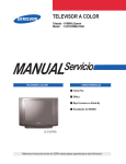
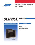
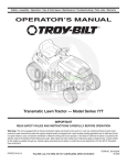
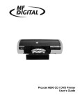
COLOR TELEVISION RECEIVER
Chassis : KS7C(N)_Timecop
Model : CL29Z43MQVXXAZ
SERVICE
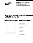
COLOR TELEVISION RECEIVER
Manual
FEATURES
■ GREEN CRT
■ Turbo Voice
CL-29Z43MQ
Exploded View & Part List
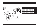
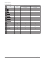
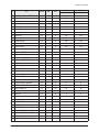
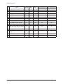
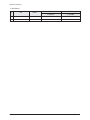
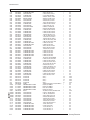
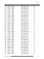
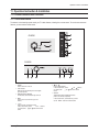
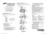
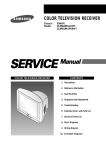
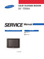
4. Exploded View & Part List
4-1 CL29Z43MQVXXAZ
M0006
T0074
T0066
T0063
T0003
M0112
Loc.No.
Code No.
Description
Specification
Q'ty
CIS3
AA64-04333A
CIS7
AA61-60003J
M0006
SA/SNA Remark
DECORATION-POWER
Z40,ABS,HB,GR515,AL
1
S.N.A
SPRING ETC-CS
-,SUS304,-,-,OD6,N7,OD6,-,
1
S.N.A
AA63-01426D
COVER-REAR
29Z43(SEDA),HIPS,HB,BK500
1
S.N.A
M0014
AA94-16462A
ASSY PCB MAIN
CL29Z43MQVXXAZ
1
S.A
M0112
AA63-01428J
COVER-FRONT
29Z43(SEDA),HIPS,HB,BKN1576,
1
S.N.A
T0003
AA96-04151N
ASSY COVER P-FRONT
29Z43,HIPS,HB,BKN1576
1
S.A
T0022
AA64-04327A
KNOB CONTROL
29Z40,SEH,ABS,-,-,-,HB,GR51
1
S.N.A
T0023
AA64-04328A
KNOB POWER
Z40,ABS,HB,GR515,SVM3012
1
S.N.A
T0063
AA03-00559A
CRT COLOR
A68QGX793X601(M),0mG,0.985,1.3
1
S.A
T0066
AA96-02795A
ASSY POWER CORD
CP2/NO(4.0),H/S 300mm,CH
1
S.A
T0074
AA59-00410B
REMOCON
SAMSUNG,TM85,S3C1860XP0,35,NTSC,
1
S.A
T0238
AA64-04340A
WINDOW REMOCON-LED
Z40(SEH,TSE),PC,CLEAR
1
S.N.A
T0569
AA61-00813D
SUPPORT-CRT
29Z30(SLIM),HIPS V0,T2.0,-,-
2
S.N.A
T0607
AA61-40113A
STOPPER-PCB
501H,HIPS,-,-,HB,NTR,-
1
S.N.A
T0569
T0238
T0022
T0607
M0014
CIS3
CIS7
T0023
Samsung Electronics
4-1
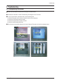
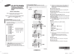
Disassembly & Reassembly
12. Disassembly & Reassembly
12-1 Overall Disassembly & Reassembly
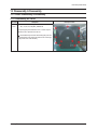
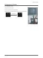
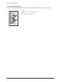
12-1-1 Disassembling the Cabinet
Part Name
Back
Cover
Description
Description Photo
① Remove the 9 screws fixing the Back Cover.
: RH, +, B, M4, L15, ZPC(BLK), SWRCH18A
② Tap the upper part of the Back Cover 2 or 3 times and pull
the Back Cover to separate it from the unit.
: Disassemble the product after disconnecting the power cord
and discharge the unit to prevent an electric shock and damage
to the product due to static electricity.
Samsung Electronics
12-1
Disassembly & Reassembly
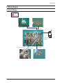
12-1-2 Disassembling the CRT and Chassis
Part Name
Chassis
Holder
Description
Description Photo
① Remove the screw,and Separate the Terminal Board.
② Separate the cables connecting the FBT and the CRT.
: Since there may be a remaining high-voltage current within
the CRT, take care not to touch the CRT hole with metal or a
part of yourself when separating the cables.
① Separate the CRT Ass'y from the CRT.
② Separate the TBC wire, cables from the CRT Ass'y
sequentially.
① Separate the Side AV Wire from the
Front Cabinet and the Main Board.
② Pull Holder Chassis like the picture arrowdirection.
① Separate the Control 4P Wire,6P Wire,Speaker Wire
from the Front Cabinet and the Main Board.
12-2
Samsung Electronics
Disassembly & Reassembly
Part Name
Chassis
Holder
Description
Description Photo
① Separate the Power cord,D-COIL,TILT,DY connector from
Main Board
① Remove the screw.
Samsung Electronics
12-3
Disassembly & Reassembly
12-1-3 Disassembling the CRT Ass'y
Part Name
CRT
Ass'y
Description
Description Photo
① Separate the cables from the Main Board and CRT Ass'y
① Separate the wires from the FBT of the Main Board and
the CRT Ass'y.
② To separate the thick red wires, pull the wires while pressing
the push-type clip at the connector.
Pull the wires while
pressing on the fixing clip.
③ To separate the thin red wire, insert a pin in the small hold
next to the hole and pull the wire.
: Take care when separating the wires because pulling the
wires by force may damage the socket. In addition, separate the
wires on a flat and clean surface so as to prevent scratching of
the material and the PCB.
12-4
Samsung Electronics
Disassembly & Reassembly
12-1-4 Disassembling the Main Board
Part Name
Description
Description Photo
Main Board ① Separate the cable from the Main Board.
① Separate the cable from the Main Board.
Samsung Electronics
12-5
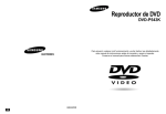
PCB Diagram
9. PCB Diagram
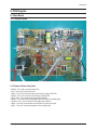
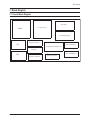
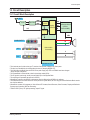
9-1 Main Board
9-1-1 Assy Main Board
PD801S LC801S
CNV901A CN902
CN601
CN503A
FN01
CN502
CN702A
CN701
9-1-2 Names & Roles of Key Parts
* PD801S : This is a 3P connected to Power-cord.
* FN01 : This is a 4P connected to Tilt-Coil.
* CN502 : This is a 6P connected to Video amp B+,Heater Voltage in CRT PCB.
* CN702A : This is a 7P connected to S-VHS signal in Side AV PCB.
* CN701: This is a 8P connected to AV2 signal in Side AV PCB.
* CN503A : This is a 8P connected from MAIN PCB to CRT PCB for R,G,B,AKB signal.
* CNV901A : This is a 6P connected from Tact,S/W pcb for IR,LED,5V.
* CN902 : This is a 4P connected from Control PCB for Key1,Key2 input signal.
* CN601 : This is a 4P connected to Speaker for Sound output signal.
Samsung Electronics
9-1
PCB Diagram
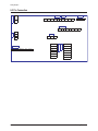
9-1-3 Main Board Connector Pin
CN601
Connected to the Side Sound Port
PIN No.
Pin Name
PIN No.
Pin Name
1
R-
1
B
2
R+
2
G
3
L+
3
R
4
L-
4
GND
5
SE
6
GND
7
F/B
8
TILT
CN503B
Connecte to the CRT Ass'y
9-2
CN503A
Connected to the CRT Ass'y
CN701
Connected to the Side AV Port
PIN No.
Pin Name
PIN No.
Pin Name
1
-16.5V
1
VO
2
+16.5V
2
GND
3
GND
3
VI
4
HEATER
4
GND
5
NC
5
LO
6
200V
6
RO
7
LI
8
RI
Samsung Electronics
PCB Diagram
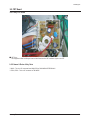
9-2 CRT Board
9-2-1 Assy CRT Board
CN503
GT501,GT502
■ CRT Drive
This supplies the final R/G/B signal from the Main Board and the CRT deflection signal to the CRT.
9-2-2 Names & Roles of Key Parts
* CN503 : This is a 14P connected from MAIN PCB for R/G/B/AKB/HEATER/B+200V.
* GT501,GT502 : This is a 2P connected to TBC-WIRE.
Samsung Electronics
9-3
PCB Diagram
9-2-3 CRT Board Connector Pin
CN503
Connects the R/G/B signal and power for the CRT and AMP
from the Main Board.
9-4
PIN No.
Pin NAME
1
B
2
G
3
R
4
GND
5
SE
6
GND
7
F/B
8
TILT
9
-16.5
10
+16.5
11
GND
12
Heater
13
NC
14
+200V
Samsung Electronics
Block Diagram
7. Block Diagram
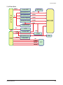
7-1 Overall Block Diagram
So u n d B l o c k
S MPS
2 ' n D Po w e r B l o c k
P I P M o d u l e ( Op t i o n al )
H o r i zo n t al D e f l e c t i o n
T ILT
SU B T U N E R( O p t i o n )
V C T i ( M i o c m . C h r o m a / So u n d I F )
E/ W B l o c k
M a i n T U N E R( O p t i o n )
FBT
V E RT I C A L D e f l e c t i o n
Samsung Electronics
A V ,M - OU T B L OC K
7-1
Block Diagram
7-2 Partial Block Diagram
7-2-1 System Board Block Diagram
7-2
Samsung Electronics
Alignment & Adjustment
3. Alignment & Adjustment
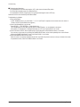
3-1 Service Instruction
1. General Adjustment :
In general, a color TV can provide ideal visual quality by adjusting the basic settings such as the vertical size, horizontal size,
focus, etc.
Display a black and white picture on the screen to check if the picture is clearly displayed.
If there are some 'spotted' points on the screen when displaying a black and white picture, degauss the screen using the
degauss coil. If the spotted points remain, re-adjust the purity and the convergence. This completes the basic performance
examination.
Notice.
■ These adjustments and the check list are only applied to KS7C chassis-applied models.
■ North America use 110V, South Central America use 220v for the measurement set.
It is recommended using an insulation transformer when supplying power to the set so as to prevent shock to the set
or to yourself.
■ These adjustment specifications have been created on the basis of the domestic KS7C chassis-applied remote
control model. Some of the contents may be changed subject to the sales location and the product specifications.
2. When replacing the Main Board :
Focus adjustment, screen voltage setting and W/B adjustment are all required.
3. When replacing the CRT Ass'y : No adjustments required.
4. When replacing the Side AV : No adjustments required.
Samsung Electronics
3-1
Alignment & Adjustment
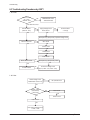
3-2 How to Access Service Mode
1. To enter Service Mode, press the keys on the remote control according to the following sequence. (in Stand-by status)
Mute → 1 → 8 → 2 → Power On
※ When failing to enter Service Mode, repeat the procedure above.
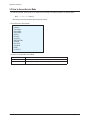
2. The initial screen of Service Mode.
Deflection
Video Adujst1
Video Adujst2
Video Adujst3
OPTION
OPTION2
YC DELAY
TEST PATTERN
EEPROM
BUS STOP
CHCKSUM
RESET
G2 ADJUST
3. Functions of the Keys within Service Mode
3-2
MENU
Show all menus
▲ /▼
Move the cursor to select an item.
◀/▶
Adjust the selected configuration value
Samsung Electronics
Alignment & Adjustment
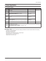
3-3 Factory Data
★ The underlined are items applied during the service adjustment. None of the others should be adjusted.
1. Deflection(NT 60Hz)
No
Item
Remark
29" SLIM
29" SLIM
CL-29Z30PQ
CL-29Z30MQ
1
V Amp
ADJ
42
42
2
V Shift
ADJ
-24
-24
3
H EW
ADJ
-6
-6
4
H Shift
ADJ
130
130
5
V Linearity
ADJ
-3
-3
6
V SC
FIX
43
43
7
H Parabola
ADJ
78
78
8
Upper Corner
ADJ
11
11
9
Lower Corner
ADJ
-29
-29
10
Upper Corner6
FIX
-18
-18
11
Lower Corner6
FIX
3
3
12
H Trapezium
ADJ
29
29
13
Bow
ADJ
2
2
14
Angle
FIX
-1
-1
15
EHT Time
FIX
20
20
16
EHT Threshold
FIX
1
1
17
EHT Vertical
FIX
0
0
18
EHT Horizontal
FIX
24
24
19
EHT Vertical2
FIX
4
4
20
EHT Horizontal2
FIX
7
7
Samsung Electronics
3-3
Alignment & Adjustment
2. Deflection(PAL 50Hz)
No
Item
Remark
29" SLIM
29" SLIM
CL-29Z30PQ
CL-29Z30MQ
1
V Amp
ADJ
4
4
2
V Shift
ADJ
-5
-5
3
H EW
ADJ
2
2
4
H Shift
ADJ
-17
-17
5
V Linearity
ADJ
0
0
6
V SC
FIX
0
0
7
H Parabola
ADJ
2
2
8
Upper Corner
ADJ
-7
-7
9
Lower Corner
ADJ
-5
-5
10
Upper Corner6
ADJ
4
4
11
Lower Corner6
ADJ
6
6
12
H Trapezium
ADJ
-8
-8
13
Bow
FIX
2
2
14
Angle
FIX
0
0
15
EHT Time
FIX
20
20
16
EHT Threshold
FIX
1
1
17
EHT Vertical
FIX
0
0
18
EHT Horizontal
FIX
24
24
19
EHT Vertical2
FIX
4
4
20
EHT Horizontal2
FIX
7
7
3-4
Samsung Electronics
Alignment & Adjustment
0 V-AMP
6
H-Parabola
1 V-Shift
7
Upper Coner
2 H EW
8
Low Coner
3 H-Shift
9
H-Trapezium
4 V-Linearity
10 BOW
5 V SC
11 Angle
Samsung Electronics
3-5
Alignment & Adjustment
3. Video Adjust 1
No
Item
Remark
29" SLIM
29" SLIM
CL-29Z30PQ
CL-29Z30MQ
1
R Cutoff
ADJ
127
127
2
G Cutoff
FIX
127
127
3
B Cutoff
ADJ
127
127
4
R Drive
ADJ
127
127
5
G Drive
FIX
127
127
6
B Drive
ADJ
127
127
7
Sub Bright
ADJ
52
52
8
Sub Contrast
ADJ
32
32
9
Sub Color
FIX
2
2
10
Sub Tint
FIX
46
46
11
AKB Option
FIX
1
1
12
BCL Threshold
FIX
19
19
13
BCL Gain
FIX
240
240
14
BCL Time
FIX
255
255
15
Sub Sharpness
FIX
12
12
16
Pilot Low
FIX
7
7
17
Pilot High
FIX
13
13
18
V-Mute(x100ms)
FIX
3
3
19
BCL TCUP
FIX
100
100
3-6
Samsung Electronics
Alignment & Adjustment
4. Video Adjust 2
No
Item
Remark
29" SLIM
29" SLIM
CL-29Z30PQ
CL-29Z30MQ
1
VSU
FIX
2
2
2
Melody Volume
FIX
5
5
3
HB Start
FIX
159
159
4
HB Stop
FIX
149
149
5
RF AGC
FIX
4
4
6
VM Gain
FIX
0
0
7
VM Delay
FIX
0
0
8
V Peaking
FIX
12
12
9
BLE Tilt
FIX
12
12
10
BLE Gain
FIX
1
1
11
BLE Mode
FIX
2
2
12
BLE Break
FIX
1
1
13
CTI Gain
FIX
1
1
14
CTI Coring
FIX
15
15
15
LTI Gain
FIX
15
15
16
D-EHT Time
FIX
5
5
17
DCT Ratio
FIX
50
50
18
VSP COMB
FIX
3
3
Samsung Electronics
3-7
Alignment & Adjustment
5. Video Adjust 3
No
Item
Remark
29" SLIM
29" SLIM
CL-29Z30PQ
CL-29Z30MQ
1
NR Off Value
FIX
3
3
2
Gamma Mode
FIX
1
1
3
Gamma Correction
FIX
70
70
4
BST StartPoint
FIX
145
145
5
BST Gain(B)
FIX
50
50
6
DPWL Gain
FIX
80
80
7
DPWL Start
FIX
185
185
8
PIP Contrast
FIX
8
8
9
PIP Tint
FIX
57
57
10
PIP Color
FIX
6
6
11
PIP PAL V.Pos
FIX
24
24
12
PIP NTSC V.Pos
FIX
24
24
13
PIP H.Pos
FIX
46
46
14
PIP R Cutoff
FIX
6
6
15
PIP B Cutoff
FIX
9
9
16
PIP R Drive
FIX
161
161
17
PIP B Drive
FIX
141
141
29" SLIM
29" SLIM
CL-29Z30PQ
CL-29Z30MQ
6. YC Delay
No
Item
Remark
1
PAL Delay
FIX
0
0
2
SECAM Delay
FIX
-2
-2
3
NTSC Delay
FIX
0
0
4
PAL(AV) Delay
FIX
0
0
5
SECAM(AV) Delay
FIX
-3
-3
6
NTSC(AV) Delay
FIX
0
0
3-8
Samsung Electronics
Alignment & Adjustment
7. Test Pattern
No
Item
Remark
29" SLIM
29" SLIM
CL-29Z30PQ
CL-29Z30MQ
1
G2 Adjust
-
-
-
2
Read Cut
-
-
-
3
Read Drive
-
-
-
4
IBRM
FIX
180
180
5
WDRM
FIX
50
50
6
CDL
FIX
254
254
7
COLR G B
FIX
50 / 50 / 50
50 / 50 / 50
Samsung Electronics
3-9
Alignment & Adjustment
8. EEPROM
No
Item
Remark
MIN
MAX
29" SLIM
29" SLIM
CL-29Z30PQ
CL-29Z30MQ
0
Dynamic Contrast
FIX
0
255
100
100
1
Dynamic Brightness
FIX
0
255
45
45
2
Dynamic Sharpness
FIX
0
255
65
65
3
Dynamic Color
FIX
0
255
43
43
4
Dynamic Tint
FIX
0
255
50
50
5
Standard Contrast
FIX
0
255
82
82
6
Standard Brightness
FIX
0
255
45
45
7
Standard Sharpness
FIX
0
255
50
50
8
Standard Color
FIX
0
255
45
45
9
Standard Tint
FIX
0
255
50
50
10
Movie Contrast
FIX
0
255
50
50
11
Movie Brightness
FIX
0
255
55
55
12
Movie Sharpness
FIX
0
255
25
25
13
Movie Color
FIX
0
255
40
40
14
Movie Tint
FIX
0
255
50
50
15
255
255
16
255
255
17
255
255
18
255
255
10
10
19
DVD SUB TINT
FIX
0
20
16:9 V-SHIFT
FIX
0
100
15
15
21
16:9 PARAVOLA
FIX
0
100
5
5
22
PIP BRIGHTNESS
FIX
0
15
0
0
23
Double TTX Contrast
FIX
255
255
24
TTX V Position
FIX
0
255
255
255
25
TTX H Position
FIX
0
255
255
255
26
TTX Contrast
FIX
0
255
255
255
27
TTX Brightness
FIX
0
255
255
255
28
OSD Contrast
FIX
0
255
115
115
29
OSD Brightness
FIX
0
255
15
15
30
Double TTX H Position
FIX
0
255
255
255
31
Standard Equ100(Std BASS)
FIX
0
8
50
50
32
Standard Equ300(Std TREBLE)
FIX
0
13
50
50
33
Standard Equ1K(Music BASS)
FIX
0
14
85
85
34
Standard Equ3K(Music TREBLE)
FIX
0
13
70
70
35
Standard 10K(Movie BASS)
FIX
0
12
95
95
36
Music Equ100(Movie TREBLE)
FIX
0
18
50
50
37
Music Equ300(Speech BASS)
FIX
0
14
40
40
3-10
Samsung Electronics
Alignment & Adjustment
No
Item
Remark
MIN
MAX
29" SLIM
29" SLIM
CL-29Z30PQ
CL-29Z30MQ
38
Music Equ1K(Speech TREBLE)
FIX
0
11
50
50
39
Music Equ3K
FIX
0
14
255
255
40
Music 10K
FIX
0
18
255
255
41
Movie Equ100
FIX
0
22
255
255
42
Movie Equ300
FIX
0
15
255
255
43
Movie Equ1K
FIX
0
11
255
255
44
Movie Equ3K
FIX
0
12
255
255
45
Movie 10K
FIX
0
13
255
255
46
Speech Equ100
FIX
0
6
255
255
47
Speech Equ300
FIX
0
11
255
255
48
Speech Equ1K
FIX
0
14
255
255
49
Speech Equ3K
FIX
0
13
255
255
50
Speech 10K
FIX
0
11
255
255
51
Brightness(RGB/DVD)
FIX
0
255
6
6
52
Contrast(RGB/DVD)
FIX
0
63
42
42
53
U Saturation(RGB/DVD)
FIX
0
63
44
44
54
V saturation(RGB/DVD)
FIX
0
63
43
43
55
V/FBL Delay
FIX
0
255
85
85
56
CrCb Delay
FIX
0
255
84
84
57
d/w h-position
FIX
0
255
255
255
58
d/w -blanking 1
FIX
0
255
255
255
59
d/w -blanking 2
FIX
0
255
255
255
60
PIP G CUTOFF
FIX
0
255
4
4
61
PIP G DRIVE
FIX
0
255
170
170
62
OSD/PIP BRIGHT BALANCE
FIX
0
31
31
31
63
PIP BRIGHT OFFSET
FIX
0
255
86
86
64
MDB_STRENGTH
FIX
0
127
68
68
65
MDB_HARMONIC
FIX
0
127
37
37
66
MDB_HP
FIX
0
30
9
9
67
MDB_LP
FIX
0
30
11
11
68
MDB_LIM
FIX
0
255
252
252
69
MDB_CUTOFF
FIX
0
40
12
12
70
EHT POSITION 1
FIX
0
255
5
5
71
EHT POSITION 2
FIX
0
255
249
249
72
3.4CH SLLTHD (TV-NO NOISE)
FIX
0
3
0
0
73
CH SLLTHD (TV-NO NOISE)
FIX
0
3
0
0
74
LNA Operating Point
FIX
0
255
166
166
75
SLLTHDV(TV NO NOISE)
FIX
0
6
0
0
Samsung Electronics
3-11
Alignment & Adjustment
No
Item
Remark
MIN
MAX
29" SLIM
29" SLIM
CL-29Z30PQ
CL-29Z30MQ
76
LNA Default
FIX
0
1
0
0
77
LNA SWITCH
FIX
0
1
0
0
78
LMIXOFS
FIX
0
13
13
13
79
H-OUTDEL
FIX
0
255
72
72
80
CR-P Initial
FIX
0
255
4
4
81
CR-I Initial
FIX
0
255
5
5
82
DRX_CR_AMP_TH
FIX
0
255
10
10
83
Over Modulation Return Counter
FIX
0
255
100
100
84
VCR Mode Counter
FIX
0
255
5
5
85
"VID_AMP_HEAD_BS(In the modulation)"
FIX
0
255
40
40
86
CR_P (In the Over Modulation)
FIX
0
255
4
4
87
"THRSEL(picture shaking when weak
signal)"
FIX
0
255
2
2
88
SLLTHDVP
FIX
0
255
1
1
89
EEP_BC_MIN_LIMIT
FIX
0
255
150
150
3-12
Samsung Electronics
Alignment & Adjustment
9. OPTION
No
Item
29" SLIM
29" SLIM
CL-29Z30PQ
CL-29Z30MQ
1
System
CL
CL
2
ACS
Off
Off
3
AV Jack
2RCA+S+DVD
2RCA+S+DVD
4
Tilt
On
On
5
Vchip
Off
Off
6
Caption
On
On
7
PIP
Off
2-Tuner
8
LNA
Off
On
9
Auto On
Off
Off
10
StandBy LED
Off
Off
11
Philippines(AV MULTI)
Off
Off
12
Osd Language
English
English
13
FM Radio
Off
Off
14
Antenna Disp
Off
Off
15
Hi-Deviation
Off
Off
16
Plug & Play
On
On
17
DNIe Jr
Off
Off
18
Volume Curve
Small
Small
19
Color Matrix
Japan
Japan
20
PWM/Parabola
Parabola
Parabola
Samsung Electronics
3-13
Alignment & Adjustment
11. White Balance
No
Item
Remark
29" SLIM
29" SLIM
CL-29Z30PQ
CL-29Z30MQ
1
H
-
269± 3/274± 3/40± 0.3
269± 3/274± 3/40± 0.3
2
L
-
269± 3/274± 3/2.0± 0.2
269± 3/274± 3/2.0± 0.2
3-14
Samsung Electronics
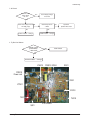
Alignment & Adjustment
3-4 Service Adjustment
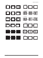
3-4-1 Adjusting the Picture Size
■ Since the KS7C chassis has the deflection settings data within the Factory Data, the picture size has to be adjusted when
replacing Main Board, according to the following procedures.
① Display the Lion pattern.
② Press "Power Off → Mute → 1 → 8 → 2 → Power On"
using the remote control and enter Factory Mode.
③ Enter Deflection Mode.
④ Adjust the V-AMP, V-SHIFT, H-AMP and H-SHIFT items so
that the width becomes 5 and the height becomes 4.
44
55
4 4
55
5 5
5 5
44
4 4
Samsung Electronics
3-15
Alignment & Adjustment
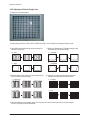
3-4-2 Adjusting the Picture Straight Lines
① Display the Cross Hatch pattern.
② Adjust settings other than V-AMP, V-SHIFT, H-AMP and H-SHIFT so that straight lines are displayed without curves.
③ Adjust BOW and the Angle settings so that the center line
becomes a straight line.
④ Adjust the H-Parabola and H-Trapezium settings so that
the left and right lines become straight.
10 BOW
6
H-Parabola
11 Angle
9
H-Trapezium
⑤ Adjust the Upper Corner and the Low Corner settings so that
the end of the lines become straight.
⑥ Adjust the V-Linearity and V-SC settings so that the
intervals of the horizontal lines become uniform.
7
Upper Coner
4 V-Linearity
8
Low Coner
5 V SC
⑦ When the adjustments are complete, display the Lion pattern and check that the picture size has not been changed.
If there is no change, finish the adjustments.
3-16
Samsung Electronics
Alignment & Adjustment
3-5 Replacements & Calibration
3-5-1 Adjusting the Focus
1. Display the Cross Hatch pattern.
2. Turn the Focus clockwise to the optimal position.
3. Slowly turn the Focus clockwise so that the cross line is the most clearly displayed.
After Adjustment
Focus
Samsung Electronics
3-17
Alignment & Adjustment
3-5-2 Adjusting the Screen Voltage
1. Select "Power Off → Mute → 1 → 8 → 2 → Power On" to enter Service Mode.
2. Display the Toshiba pattern.
Screen
3. Use remocon come into "G2 Adjust" mode by hand.
4. Turn Screen VR of FBT and confirm the characters below changed from RED to GREEN.
3-18
Samsung Electronics
Alignment & Adjustment
3-5-3 Adjusting the White Balance
1. Select "Power Off → Mute → 1 → 8 → 2 → Power On" to enter Service Mode.
2. Initialize all settings to the values appropriate to the corresponding model.
3. Display the Toshiba pattern and adjust the White Balance using CA100 with the coordinates of the corresponding model.
4. Enter Video Adjust1 of Service Mode. Adjust Low/Light.
- Adjust Sub Bright to set Y.
- Adjust B Cutoff to set y.
- Adjust R Cutoff to set x.
5. Enter Video Adjust1 of Service Mode. Adjust High/Light.
- Adjust Sub Contrast to set Y.
- Adjust B Drive to set y.
- Adjust R Drive to set x.
6. Check Low/Light and readjust it if its value has been changed.
7. If you have readjusted Low/Light, readjust High/Light until the two values are identical to the coordinates of the corresponding
model.
※ White Balance Standard Data
No
Item
1
White Balance
29" SLIM
29" SLIM
CL-29Z30PQ
CL-29Z30MQ
269± 3/274± 3/40± 0.3
269± 3/274± 3/2.0± 0.2
269± 3/274± 3/40± 0.3
269± 3/274± 3/2.0± 0.2
Required Adjustment
White Balance
(Standardization Applied)
3-5-4 Check List for the Screen Voltage and White Balance Adjustment
1. The Screen Voltage and White Balance are connected each other, and both of them have to be configured to the correct values.
2. Adjust the White Balance after the Screen Voltage was adjusted, and check if the Screen Voltage is normal after adjusting the
White Balance.
3. If the White Balance is readjusted, check the Screen Voltage again.
4. When the adjustment is finished, check the following checklist.
- If there is a spot on the screen when turning the TV set off/on, adjust the Screen Voltage again.
- If there is a ghost line on the screen, adjust the Screen Voltage again.
Samsung Electronics
3-19
Circuit Description
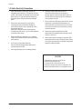
13. Circuit Description
13-1 Overall Block Description
ANT
IFIN+
Saw Filter IFIN -
Tuner
Video
Video
Sound
Sound IF
IF
Hout
Display
Display Vert
Deflection
Deflection
EW
I 2C
I 2C
Deflection Block
(HTR &
Vertical AMP)
Controller
H/V
I 2C
R
COMPONENT
G
B
AV1
Video Audio
Processing
L
R
AV2
MICOM BLOCK
* The functional part of a direct view type TV consists of the System, Deflection and Power parts.
* The Assy's are classified by the corresponding functions, by adopting GREEN CRT.
* The Power Block is different from the KS7A's in the power supply chip. STR and TRANS have been changed.
Assy's has been changed too.
* The System Block is looked similar to that for the existing model (KS7A).
* The AV signal is input through the AV port and Side AV port of the System Block.
* The audio signal is processed as same as for KS7A'S.
* Micom Block is same as the KS7A'S in the hartware. But it is different from KS7A'S in the software.
* The Deflection Block is consists of the CRT Driver part of the System Block, the CRT Assy part and the Deflection Block controls
the all of the deflection.
* Micom Block consists of five aspects as: Video & Sound IF Processor,Sound Processor, Video Processor, Display and Deflection
Processor and Controller, OSD,Text Processing.
* TDQ-6F/13F2S (Tuner): RF signal processing, output IF signal.
Samsung Electronics
13-1
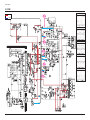
Circuit Description
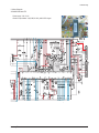
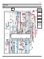
13-2 Partial Block Description
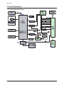
13-2-1 System Board Block Description
Tuner
IF-OUT
SCL SDA
A-1-IN
A-2-IN
JAR701
EXTERNAL A/V
INPUT/OUTPUT
TERMINAL AUDIO
PART (RCA)
A-1-OUT
A-2-OUT
A-L-OUT
IC602
TDA7266SA/
TDA7297SA
FROM EXTERNAL TERMINAL
Y Pb Pr
ICV201 VCTI
VCT49XX
DRX+VSP+DDP+MSP+Micom
HC101
PRE-AMP
FROM HEATER
A-R-OUT
R-DRIVE/OUT
G-DRIVE/OUT
IC501
TDA6109JF
CRT&D-YORK
B-DRIVE/OUT
H.V/OUT
SCL
V-AMP/OUT
SDA
VDP IN
IC902
EEPROM
24C161
SCL
TO IC501
VCC 200V
+16.5V
-16.5V
IC301
LA78045
SDA
H-DRIVE /IN
Q401
2SC5936
FROM
A+5.0V
H.V/OUT
S
C
R
E
E
N
F
O
C
U
S
V
O
L
T
A
G
E
V
O
L
T
A
G
E
H
I
G
H
H
E
A
T
E
R
V
O
L
T
A
G
E
FBT FUH29A001G
DVD_SVHS
EXTERNAL DVD
INPUT TERMINAL
(RCA)
Pr
Pb
Y
ICV201 Y/Pb/Pr
INPUT PORT
TUNER 33V
KAC2231
125V
B+8V
TO SOUND AMP VCC 14V
IC801S
STR W6750F
T801S
Switch Trans
TO FBT VCC 125V
KA78R05
KA78RM33
KSC2331
KSC2331
B+5V
A+3.3V
A+5V
B+3.3V
* VCT4953: DRX+VSP+MSP+TVT. It contains the entire IF, audio, video, display and deflection processing for 4:3 and 16:9
50/60Hz mono and stereo TV sets. The integrated microcontroller is supported by a powerful OSD generator with integrated
Teletext and CC acquisition including on-chip page memory.
* 2SC5936: Inputed H-DRIVE signal which comes from VCT4953.It amplify the H-DRIVE then output to Deflection Yoke.
* LA78045: Inputed VDP signal which comes from VCT4953.It amplify the VDP then output to Deflection Yoke.
* TDA7266SA/TDA7297SA: It is a dual channel audio amplifier.The two audio signals L and R input to it and are amplified, then
output to speaker.
* TDA6109JF: It includes three video output amplifiers and is intended to drive the three cathodes of a color CRT directly.
G、B signals will connect to the CRT socket pins directly.
The output R、
* EEPROM: As a extended ROM of TVT. It contains some data which is used to program executing.
* STR W6750F: SMPS control HIC. Provide switching signal in order to control the trans working.
* TDQ-6F/13F2S(TUNER): Receives the RF signal and output a fixed IF to Micom.
13-2
Samsung Electronics
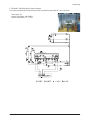
Circuit Description
13-2-2 Power Block
AMP14V
Audio AMP
Q810(KSC2331-Y)
Q810(KSC2331
-Y)
S
M
P
S
Q811(KSC2331-Y)
Q811(KSC2331
-Y)
6V
Q812A(78RM33)
EEPROM
A+5V
B+3.3V
A+3.3V
A+1.8V
MICOM
QV905(KSC1008Y)
B+5V
B+5V
IC802(78R05)
14V
130V
± 16.5V
HTR
Vertical AMP
B+33V
B+5V
TUNER
Q813(KSC2331-Y)
Q813(KSC2331
-Y)
FBT
B+210V
Video AMP
B+8V
EW
H/V
SCREEN
FOCUS
CRT
HEATER
Samsung Electronics
13-3
Circuit Description
13-2-3 IC Line Up
■ Main Board
13-4
Items
Descriptions
MICOM
VCT4953_F1 Micronas
Tuner
TECC1040SL32A(E),XUGUANG
BRIDGE DIODE
GSIB460,VISHAY
Trans Switching
42B135,DK
Remarks
STR
STR-W6750F,SANKEN
FET
FQP630TSTU,FAIRCHILD
Vertical DEF.
LA78045,SANYO
Horizontal DEF.
2SC5936M,MATSUSHITA
SOUND AMP
TDA7297SA, SGS-TOMSON
10W+10W
SOUND AMP
TDA7266SA, SGS-TOMSON
7W+7W
EEPROM
24C161,SAMSUNG
VIDEO AMP
TDA6109JF, Philips
Regulator
78R05
B+5V Regulator
Regulator
78RM33
A+3.3V Regulator
Regulator
KSC2328A-Y
A+5V Regulator
Regulator
KSC2331-Y
B+3.3V Regulator
Samsung Electronics
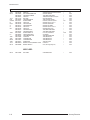
Electrical Part List
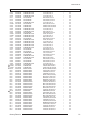
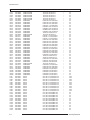
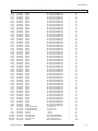
5. Electrical Part List
5-1 CL29Z43MQVXXAZ
Loc.No.
Code No.
Description
Specification
Q'ty
SA/SNA
Remark
ASSY CHASSIS
M0017
AA91-11209A
ASSY CHASSIS
CL29Z43MQVXXAZ
1
S.N.A
M0014
C
C
C
C
C
C
C
C
C
C
C
C
C
C
C
C
C
C
C
C
C
C
C
C
C
C
C
C
C
C
C
C
C
C
C
C
C
C
C
C
C
C
C
C
C
C
C
C
C
C
C
C
C
C
C
C101
AA94-16462A
2401-003025
2401-000025
2401-000025
2401-000050
2401-000050
2401-000262
2401-000262
2401-000302
2401-000360
2401-000360
2401-000430
2401-000430
2401-000430
2401-000480
2401-000493
2401-000560
2401-000603
2401-000603
2401-000703
2401-000703
2401-001026
2401-001397
2401-001397
2401-001914
2401-001914
2401-001989
2401-001989
2401-001989
2401-001989
2401-001989
2401-001989
2401-001998
2401-002075
2401-002075
2401-002075
2401-002144
2401-002144
2401-002144
2401-002144
2401-002300
2401-002463
2401-002594
2401-002619
2401-002619
2401-002619
2401-002619
2401-002619
2401-002619
2401-002619
2401-002619
2401-002619
2401-002619
2401-002619
2401-003578
2401-003578
2202-000243
ASSY PCB MAIN
C-AL
C-AL
C-AL
C-AL
C-AL
C-AL
C-AL
C-AL
C-AL
C-AL
C-AL
C-AL
C-AL
C-AL
C-AL
C-AL
C-AL
C-AL
C-AL
C-AL
C-AL
C-AL
C-AL
C-AL
C-AL
C-AL
C-AL
C-AL
C-AL
C-AL
C-AL
C-AL
C-AL
C-AL
C-AL
C-AL
C-AL
C-AL
C-AL
C-AL
C-AL
C-AL
C-AL
C-AL
C-AL
C-AL
C-AL
C-AL
C-AL
C-AL
C-AL
C-AL
C-AL
C-AL
C-AL
C-CERAMIC,MLC-AXIAL
CL29Z43MQVXXAZ
330uF,20%,400V,GP,BK,30x40,10
100uF,20%,16V,GP,TP,6.3x11,5
100uF,20%,16V,GP,TP,6.3x11,5
10uF,20%,16V,GP,TP,5x11,2.5
10uF,20%,16V,GP,TP,5x11,2.5
100uF,20%,160V,HR,TP,16x25,7.5
100uF,20%,160V,HR,TP,16x25,7.5
100uF,20%,25V,GP,TP,6.3x11,5
100uF,20%,50V,GP,TP,8x11.5,5
100uF,20%,50V,GP,TP,8x11.5,5
10uF,20%,250V,GP,TP,10x16mm,5m
10uF,20%,250V,GP,TP,10x16mm,5m
10uF,20%,250V,GP,TP,10x16mm,5m
10uF,20%,50V,GP,TP,5x11,5
10uF,20%,50V,LZ,TP,5x11mm,5mm
1uF,20%,160V,GP,TP,6.3x11,5
1UF,20%,50V,GP,TP,5X11,2
1UF,20%,50V,GP,TP,5X11,2
2200uF,20%,25V,GP,-,12.5x25mm,
2200uF,20%,25V,GP,-,12.5x25mm,
3.3UF,20%,50V,GP,TP,5X11,5
470uF,20%,25V,GP,TP,10x16,5
470uF,20%,25V,GP,TP,10x16,5
1uF,20%,50V,BP,TP,5x11,5
1uF,20%,50V,BP,TP,5x11,5
4.7uF,20%,50V,BP,TP,5x11,5
4.7uF,20%,50V,BP,TP,5x11,5
4.7uF,20%,50V,BP,TP,5x11,5
4.7uF,20%,50V,BP,TP,5x11,5
4.7uF,20%,50V,BP,TP,5x11,5
4.7uF,20%,50V,BP,TP,5x11,5
1000uF,20%,25V,GP,TP,10x20,5mm
4.7uF,20%,50V,GP,TP,5x11,5
4.7uF,20%,50V,GP,TP,5x11,5
4.7uF,20%,50V,GP,TP,5x11,5
47uF,20%,16V,GP,TP,5x11,5
47uF,20%,16V,GP,TP,5x11,5
47uF,20%,16V,GP,TP,5x11,5
47uF,20%,16V,GP,TP,5x11,5
47¥ìF,20%,50V,GP,TP,6.3x11,5mm
470uF,20%,16V,GP,TP,8x11.5,5
220uF,20%,16V,GP,TP,8x11.5,5
47uF,20%,25V,GP,TP,5x11,5
47uF,20%,25V,GP,TP,5x11,5
47uF,20%,25V,GP,TP,5x11,5
47uF,20%,25V,GP,TP,5x11,5
47uF,20%,25V,GP,TP,5x11,5
47uF,20%,25V,GP,TP,5x11,5
47uF,20%,25V,GP,TP,5x11,5
47uF,20%,25V,GP,TP,5x11,5
47uF,20%,25V,GP,TP,5x11,5
47uF,20%,25V,GP,TP,5x11,5
47uF,20%,25V,GP,TP,5x11,5
1000uF,20%,10V,GP,TP,8x20mm,5
1000uF,20%,10V,GP,TP,8x20mm,5
33pF,5%,50V,SL,TP,3.
1
1
1
1
1
1
1
1
1
1
1
1
1
1
1
1
1
1
1
1
1
1
1
1
1
1
1
1
1
1
1
1
1
1
1
1
1
1
1
1
1
1
1
1
1
1
1
1
1
1
1
1
1
1
1
1
1
S.A
S.A
S.A
S.A
S.A
S.A
S.A
S.A
S.A
S.A
S.A
S.A
S.A
S.A
S.A
S.A
S.A
S.A
S.A
S.A
S.A
S.A
S.A
S.A
S.A
S.A
S.A
S.A
S.A
S.A
S.A
S.A
S.A
S.A
S.A
S.A
S.A
S.A
S.A
S.A
S.A
S.A
S.A
S.A
S.A
S.A
S.A
S.A
S.A
S.A
S.A
S.A
S.A
S.A
S.A
S.A
S.A
Samsung Electronics
5-1
Electrical Part List
Loc.No.
Code No.
C102
C301
C302
C305
C306
C308
C400
C401
C403
C404
C405
C406
C408
C411
C413
C415
C424
C431
C504
C508
C509
C607
C608
C610
C611
C620
C627
C629
C638
C642
C644
C807
C809
C818
C820
C823
C824
C828
C843
C844
C845
C850
C888
C960
CIS1
CIS1
CIS1
CIS1
CIS1
CIS3
CN330
CN330
CN330
CN330
CN401
CR402S
CR403S
CR404S
CR406S
CV101
CV103
CV104
CV110
CV111
CV199
CV201
CV203
CV205
2202-000243
2301-000342
2201-000192
2305-000285
2003-002009
2305-000411
2305-001037
2301-000383
2201-000599
2305-000382
2301-001338
2306-000272
2201-000556
2201-000556
2201-000556
2306-000127
2201-000132
2305-000237
2301-001259
2201-000723
2201-000723
2202-000231
2202-000231
2301-000254
2301-000254
2305-000665
2202-000231
2202-000231
2202-000231
2202-000231
2202-000231
2303-000147
2201-000558
2201-000556
2201-000406
2201-000291
2305-000289
2201-000374
2301-000192
2301-000356
2201-000599
2305-001037
2201-000556
2301-000247
0205-001154
0205-001154
0205-001154
0205-001154
0205-001154
AA40-00016A
3711-001084
3711-003043
3711-003241
3711-002645
AA60-40012F
2306-000357
2306-000330
2306-000224
2301-001091
2306-000122
2301-000383
2305-000665
2301-000383
2202-002253
2202-000849
2202-000796
2202-000796
2202-000796
5-2
Description
C-CERAMIC,MLC-AXIAL
C-FILM,LEAD-PEF
C-CERAMIC,DISC
C-FILM,LEAD-PEF
R-METAL OXIDE(S)
C-FILM,LEAD-PEF
C-FILM,LEAD-PEF
C-FILM,LEAD-PEF
C-CERAMIC,DISC
C-FILM,LEAD-PEF
C-FILM,LEAD-OTHER
C-FILM,LEAD-PPF
C-CERAMIC,DISC
C-CERAMIC,DISC
C-CERAMIC,DISC
C-FILM,LEAD-PPF
C-CERAMIC,DISC
C-FILM,LEAD-PEF
C-FILM,LEAD-PPF
C-CERAMIC,DISC
C-CERAMIC,DISC
C-CERAMIC,MLC-AXIAL
C-CERAMIC,MLC-AXIAL
C-FILM,LEAD-PEF
C-FILM,LEAD-PEF
C-FILM,LEAD-PEF
C-CERAMIC,MLC-AXIAL
C-CERAMIC,MLC-AXIAL
C-CERAMIC,MLC-AXIAL
C-CERAMIC,MLC-AXIAL
C-CERAMIC,MLC-AXIAL
C-FILM,LEAD-PPF
C-CERAMIC,DISC
C-CERAMIC,DISC
C-CERAMIC,DISC
C-CERAMIC,DISC
C-FILM,LEAD-PEF
C-CERAMIC,DISC
C-FILM,LEAD-PEF
C-FILM,LEAD-PEF
C-CERAMIC,DISC
C-FILM,LEAD-PEF
C-CERAMIC,DISC
C-FILM,LEAD-PEF
OIL-SILICON
OIL-SILICON
OIL-SILICON
OIL-SILICON
OIL-SILICON
TUNER
HEADER-BOARD TO CABLE
HEADER-BOARD TO CABLE
HEADER-BOARD TO CABLE
HEADER-BOARD TO CABLE
PIN-GT
C-FILM,LEAD-PPF
C-FILM,LEAD-PPF
C-FILM,LEAD-PPF
C-FILM,LEAD-PPF
C-FILM,LEAD-PPF
C-FILM,LEAD-PEF
C-FILM,LEAD-PEF
C-FILM,LEAD-PEF
C-CERAMIC,MLC-AXIAL
C-CERAMIC,MLC-AXIAL
C-CERAMIC,MLC-AXIAL
C-CERAMIC,MLC-AXIAL
C-CERAMIC,MLC-AXIAL
Specification
33pF,5%,50V,SL,TP,3.
2.2nF,5%,50V,TP,7.4x3.9x
0.01nF,0.25pF,500V,C0G,-,
220NF,5%,100V,TP,10.5X5.
390ohm,5%,2W,AF,TP,3.9x
470nF,5%,50V,TP,7.3x4.8x
330nF,5%,63V,TP,7.5x5.5x
10nF,5%,50V,TP,6x7x3.2mm
0.56NF,10%,500V,Y5P,TP,5.
4.7nF,5%,400V,TP,-,5mm
0.68NF,5%,1.6KV,BK,28X
820nF,5%,400V,BK,29x25.5
0.47NF,10%,500V,Y5P,TP,5.
0.47NF,10%,500V,Y5P,TP,5.
0.47NF,10%,500V,Y5P,TP,5.
120nF,5%,400V,TP,21.5x17
0.1NF,10%,500V,Y5P,TP,6.5
1uF,5%,63V,TP,7.5x15.5mm
100nF,5%,400V,TP,19x8x16
4.7NF,20%,3KV,Y5U,TP,16X5
4.7NF,20%,3KV,Y5U,TP,16X5
0.33NF,10%,50V,Y5P,T
0.33NF,10%,50V,Y5P,T
39nF,5%,50V,TP,7.5x3.5x6
39nF,5%,50V,TP,7.5x3.5x6
100nF,5%,63V,TP,7.5x4.0x
0.33NF,10%,50V,Y5P,T
0.33NF,10%,50V,Y5P,T
0.33NF,10%,50V,Y5P,T
0.33NF,10%,50V,Y5P,T
0.33NF,10%,50V,Y5P,T
1NF,5%,2KV,TP,23X13X8MM,
0.47NF,10%,50V,Y5P,TP,5X3
0.47NF,10%,500V,Y5P,TP,5.
0.27NF,10%,2KV,Y5P,TP,6.3
1NF,10%,500V,Y5P,TP,7.5X3
220nF,5%,63V,TP,-,5mm
0.22NF,5%,50V,C0G,TP,10.5
1nF,5%,50V,TP,5.3x10mm,5
47nF,5%,50V,TP,7.5x4.0x6
0.56NF,10%,500V,Y5P,TP,5.
330nF,5%,63V,TP,7.5x5.5x
0.47NF,10%,500V,Y5P,TP,5.
33nF,5%,50V,TP,8.1x4.5x1
G746,-,G746,-,G746,-,G746,-,G746,-,TDQ-6F/13F2S,NTSC,181CH,45.75MHZ,7
BOX,8P,1R,2.5MM,ST
BOX,4P,1R,2.5MM,ST
BOX,14P,1R,2.5MM,S
BOX,6P,1R,2.5mm,ST
4P,2.36PI,6/12/14mm,NYLON66,LOCKI
8.2nF,5%,1.6KV,BK,20x9.5
7.7NF,3%,1.6KV,BK,28.5X1
47nF,5%,400V,TP,19x15.5x
470nF,5%,400V,BK,26x21.5
100nF,5%,50V,TP,7.3x4.0x
10nF,5%,50V,TP,6x7x3.2mm
100nF,5%,63V,TP,7.5x4.0x
10nF,5%,50V,TP,6x7x3.2mm
100.0nF,+80-20%,50.0
0.018nF,5%,50V,C0G,1nF,10%,50V,Y5P,-,2x
1nF,10%,50V,Y5P,-,2x
1nF,10%,50V,Y5P,-,2x
Q'ty
SA/SNA
1
1
1
1
1
1
1
1
1
1
1
1
1
1
1
1
1
1
1
1
1
1
1
1
1
1
1
1
1
1
1
1
1
1
1
1
1
1
1
1
1
1
1
1
0.2
0.2
0.2
0.1
0.1
1
1
1
1
1
1
1
1
1
1
1
1
1
1
1
1
1
1
1
S.A
S.A
S.A
S.A
S.A
S.A
S.A
S.A
S.A
S.A
S.A
S.A
S.A
S.A
S.A
S.A
S.A
S.A
S.A
S.A
S.A
S.A
S.A
S.A
S.A
S.A
S.A
S.A
S.A
S.A
S.A
S.A
S.A
S.A
S.A
S.A
S.A
S.A
S.A
S.A
S.A
S.A
S.A
S.A
S.N.A
S.N.A
S.N.A
S.N.A
S.N.A
S.A
S.A
S.A
S.A
S.A
S.N.A
S.A
S.A
S.A
S.A
S.A
S.A
S.A
S.A
S.A
S.A
S.A
S.A
S.A
Remark
Samsung Electronics
Electrical Part List
Loc.No.
Code No.
Description
Specification
Q'ty
SA/SNA
CV207
CV208
CV209
CV210
CV211
CV212
CV213
CV219
CV223B
CV253
CV254
CV256
CV257
CV259
CV260
CV262A
CV262B
CV271
CV299
CV601
CV612
CV643
CV902
CV904
CV908
CV910
CV911
CV912
CV913
CV914
CV915
CV920
CV933
CV934
CV935
CV999
CX801S
CY800S
CY802S
D0254
D303
D402
D403
D404
D405
D406
D407
D408
D499
D501
D502
D503
D504
D630
D801S
D803
D804
D805
D806
D807
D808
D809
D811
D813
D814
D817
D819
D820
2202-000796
2202-000796
2202-000796
2202-000796
2305-000289
2305-000665
2305-000665
2202-000796
2301-000224
2201-000389
2201-000389
2202-000796
2202-000796
2202-000279
2305-000665
2202-002253
2202-000796
2202-000243
2305-001037
2202-002253
2202-000796
2202-000231
2202-000796
2202-000796
2202-000796
2305-000412
2305-000412
2305-000665
2202-000121
2305-000665
2202-000121
2202-000863
2305-000411
2305-000411
2305-000411
2202-000796
2306-000318
2201-000987
2201-000963
0404-001056
0402-000493
0402-000132
0402-000132
0402-001599
0402-000534
0402-000540
0402-000540
0402-001295
0401-000005
0401-000006
0401-000006
0401-000006
0402-000254
0401-000005
0402-001477
0402-000546
0401-000006
0401-000006
0402-000546
0402-000005
0402-000132
0402-000005
0402-001603
0402-000493
0401-000005
0402-000132
0401-000005
0401-000005
C-CERAMIC,MLC-AXIAL
C-CERAMIC,MLC-AXIAL
C-CERAMIC,MLC-AXIAL
C-CERAMIC,MLC-AXIAL
C-FILM,LEAD-PEF
C-FILM,LEAD-PEF
C-FILM,LEAD-PEF
C-CERAMIC,MLC-AXIAL
C-FILM,LEAD-PEF
C-CERAMIC,DISC
C-CERAMIC,DISC
C-CERAMIC,MLC-AXIAL
C-CERAMIC,MLC-AXIAL
C-CERAMIC,MLC-AXIAL
C-FILM,LEAD-PEF
C-CERAMIC,MLC-AXIAL
C-CERAMIC,MLC-AXIAL
C-CERAMIC,MLC-AXIAL
C-FILM,LEAD-PEF
C-CERAMIC,MLC-AXIAL
C-CERAMIC,MLC-AXIAL
C-CERAMIC,MLC-AXIAL
C-CERAMIC,MLC-AXIAL
C-CERAMIC,MLC-AXIAL
C-CERAMIC,MLC-AXIAL
C-FILM,LEAD-PEF
C-FILM,LEAD-PEF
C-FILM,LEAD-PEF
C-CERAMIC,MLC-AXIAL
C-FILM,LEAD-PEF
C-CERAMIC,MLC-AXIAL
C-CERAMIC,MLC-AXIAL
C-FILM,LEAD-PEF
C-FILM,LEAD-PEF
C-FILM,LEAD-PEF
C-CERAMIC,MLC-AXIAL
C-FILM,LEAD-PPF
C-CERAMIC,DISC
C-CERAMIC,DISC
DIODE-SCHOTTKY
DIODE-RECTIFIER
DIODE-RECTIFIER
DIODE-RECTIFIER
DIODE-RECTIFIER
DIODE-RECTIFIER
DIODE-RECTIFIER
DIODE-RECTIFIER
DIODE-RECTIFIER
DIODE-SWITCHING
DIODE-SWITCHING
DIODE-SWITCHING
DIODE-SWITCHING
DIODE-RECTIFIER
DIODE-SWITCHING
DIODE-BRIDGE
DIODE-RECTIFIER
DIODE-SWITCHING
DIODE-SWITCHING
DIODE-RECTIFIER
DIODE-RECTIFIER
DIODE-RECTIFIER
DIODE-RECTIFIER
DIODE-RECTIFIER
DIODE-RECTIFIER
DIODE-SWITCHING
DIODE-RECTIFIER
DIODE-SWITCHING
DIODE-SWITCHING
1nF,10%,50V,Y5P,-,2x
1nF,10%,50V,Y5P,-,2x
1nF,10%,50V,Y5P,-,2x
1nF,10%,50V,Y5P,-,2x
220nF,5%,63V,TP,-,5mm
100nF,5%,63V,TP,7.5x4.0x
100nF,5%,63V,TP,7.5x4.0x
1nF,10%,50V,Y5P,-,2x
22nF,5%,50V,TP,7.4x3.9x1
0.022NF,5%,50V,C0G,TP,5X3
0.022NF,5%,50V,C0G,TP,5X3
1nF,10%,50V,Y5P,-,2x
1nF,10%,50V,Y5P,-,2x
47pF,5%,50V,SL,TP,3.
100nF,5%,63V,TP,7.5x4.0x
100.0nF,+80-20%,50.0
1nF,10%,50V,Y5P,-,2x
33pF,5%,50V,SL,TP,3.
330nF,5%,63V,TP,7.5x5.5x
100.0nF,+80-20%,50.0
1nF,10%,50V,Y5P,-,2x
0.33NF,10%,50V,Y5P,T
1nF,10%,50V,Y5P,-,2x
1nF,10%,50V,Y5P,-,2x
1nF,10%,50V,Y5P,-,2x
470nF,5%,63V,TP,-,5mm
470nF,5%,63V,TP,-,5mm
100nF,5%,63V,TP,7.5x4.0x
0.1nF,10%,50V,Y5P,-,
100nF,5%,63V,TP,7.5x4.0x
0.1nF,10%,50V,Y5P,-,
560pF,10%,50V,Y5P,TP
470nF,5%,50V,TP,7.3x4.8x
470nF,5%,50V,TP,7.3x4.8x
470nF,5%,50V,TP,7.3x4.8x
1nF,10%,50V,Y5P,-,2x
220nF,20%,275V,BK,26x7x1
2.2NF,20%,400V,Y5U,BK,12.
1NF,20%,400V,Y5U,TP,9.5X6
RK16,60V,1500MA,DO-204AC,
1R5GU41,400V,1.5A,DO-15L
1N4004,400V,1A,DO-41,TP
1N4004,400V,1A,DO-41,TP
DGP30L,1500,3A,DO-201AD(
RG10V,400V,1.2A,DO-15,TP
RU20A,600V,1.5A,DO-15,TP
RU20A,600V,1.5A,DO-15,TP
GUR460L-5700,600V,4A,DO1N4148,75V,150mA,DO-35,T
BAV21,250V,200mA,DO-35,T
BAV21,250V,200mA,DO-35,T
BAV21,250V,200mA,DO-35,T
RGP10J,600V,1A,DO-41,TP
1N4148,75V,150mA,DO-35,T
GSIB460,600V,4A,SIP-4,ST
TVR10G,400V,1A,DO-41,TP
BAV21,250V,200mA,DO-35,T
BAV21,250V,200mA,DO-35,T
TVR10G,400V,1A,DO-41,TP
31DF4,400V,3A,DO-201AD,B
1N4004,400V,1A,DO-41,TP
31DF4,400V,3A,DO-201AD,B
MUR480E,800V,4A,DO-201AD
1R5GU41,400V,1.5A,DO-15L
1N4148,75V,150mA,DO-35,T
1N4004,400V,1A,DO-41,TP
1N4148,75V,150mA,DO-35,T
1N4148,75V,150mA,DO-35,T
1
1
1
1
1
1
1
1
1
1
1
1
1
1
1
1
1
1
1
1
1
1
1
1
1
1
1
1
1
1
1
1
1
1
1
1
1
1
1
1
1
1
1
1
1
1
1
1
1
1
1
1
1
1
1
1
1
1
1
1
1
1
1
1
1
1
1
1
S.A
S.A
S.A
S.A
S.A
S.A
S.A
S.A
S.A
S.A
S.A
S.A
S.A
S.A
S.A
S.A
S.A
S.A
S.A
S.A
S.A
S.A
S.A
S.A
S.A
S.A
S.A
S.A
S.A
S.A
S.A
S.A
S.A
S.A
S.A
S.A
S.A
S.A
S.A
S.A
S.A
S.A
S.A
S.A
S.A
S.A
S.A
S.A
S.A
S.A
S.A
S.A
S.A
S.A
S.A
S.A
S.A
S.A
S.A
S.A
S.A
S.A
S.A
S.A
S.A
S.A
S.A
S.A
Samsung Electronics
Remark
5-3
Electrical Part List
Loc.No.
Code No.
DV201
DV202
DV203
DV901
DV951
DV952
DZ201
DZ202
DZ203
DZ242
DZ301
DZ302
DZ303
DZ305
DZ306
DZ403
DZ501
DZ502
DZ503
DZ603
DZ701
DZ702
DZ703
DZ801
DZ802
DZ804
DZ806
DZ807
DZ808
DZ810
DZ811
DZ812
DZ813
DZ814
DZ815
DZ816
DZ905
DZV01
DZV02
DZV101
DZV200
DZV299
DZV901
DZV902
EL301
EL302
EL800
EL801
EL803
EL804
EL805
EL806
EL807
EL886
EL888
EY301
EY600
EY601
EY602
EY603
EY800
EY801
EY802
EY803
EY804
EY805
EY806
EY807
0401-000005
0401-000005
0401-000005
0401-000005
0401-000005
0401-000005
0403-000720
0403-000720
0403-000720
0403-000719
0403-001329
0403-001329
0403-001221
0403-001329
0403-000700
0401-000005
0403-001211
0403-001211
0403-001211
0403-000720
0403-000720
0403-000720
0403-000720
0403-000714
0403-000509
0403-001322
0403-000720
0403-000718
0403-000720
0403-000509
0403-000700
0403-000700
0403-000720
0403-001320
0403-001321
0401-000005
0403-001317
0403-000720
0403-000720
0403-000509
0403-000509
0403-000509
0403-000509
0403-000509
6042-000001
6042-000001
6042-000001
6042-000001
6042-000001
6042-000001
6042-000001
6042-000001
6042-000001
6042-000001
6042-000001
6042-000002
6042-000002
6042-000002
6042-000002
6042-000002
6042-000002
6042-000002
6042-000002
6042-000002
6042-000002
6042-000002
6042-000002
6042-000002
5-4
Description
DIODE-SWITCHING
DIODE-SWITCHING
DIODE-SWITCHING
DIODE-SWITCHING
DIODE-SWITCHING
DIODE-SWITCHING
DIODE-ZENER
DIODE-ZENER
DIODE-ZENER
DIODE-ZENER
DIODE-ZENER
DIODE-ZENER
DIODE-ZENER
DIODE-ZENER
DIODE-ZENER
DIODE-SWITCHING
DIODE-ZENER
DIODE-ZENER
DIODE-ZENER
DIODE-ZENER
DIODE-ZENER
DIODE-ZENER
DIODE-ZENER
DIODE-ZENER
DIODE-ZENER
DIODE-ZENER
DIODE-ZENER
DIODE-ZENER
DIODE-ZENER
DIODE-ZENER
DIODE-ZENER
DIODE-ZENER
DIODE-ZENER
DIODE-ZENER
DIODE-ZENER
DIODE-SWITCHING
DIODE-ZENER
DIODE-ZENER
DIODE-ZENER
DIODE-ZENER
DIODE-ZENER
DIODE-ZENER
DIODE-ZENER
DIODE-ZENER
EYELET
EYELET
EYELET
EYELET
EYELET
EYELET
EYELET
EYELET
EYELET
EYELET
EYELET
EYELET
EYELET
EYELET
EYELET
EYELET
EYELET
EYELET
EYELET
EYELET
EYELET
EYELET
EYELET
EYELET
Specification
1N4148,75V,150mA,DO-35,T
1N4148,75V,150mA,DO-35,T
1N4148,75V,150mA,DO-35,T
1N4148,75V,150mA,DO-35,T
1N4148,75V,150mA,DO-35,T
1N4148,75V,150mA,DO-35,T
MTZJ9.1B,8.57-9.01V,500mW,DO
MTZJ9.1B,8.57-9.01V,500mW,DO
MTZJ9.1B,8.57-9.01V,500mW,DO
MTZJ7.5B,7.11-7.44V,500mW,DO
MTZJ24B,22.75-23.73V,500mW,D
MTZJ24B,22.75-23.73V,500mW,D
UZ39BSB,35.36-37.19V,500mW,D
MTZJ24B,22.75-23.73V,500mW,D
TZP33A,5%,1000mW,DO-41,TP
1N4148,75V,150mA,DO-35,T
MTZJ12B,11.8-12.3V,500mW,DOMTZJ12B,11.8-12.3V,500mW,DOMTZJ12B,11.8-12.3V,500mW,DOMTZJ9.1B,8.57-9.01V,500mW,DO
MTZJ9.1B,8.57-9.01V,500mW,DO
MTZJ9.1B,8.57-9.01V,500mW,DO
MTZJ9.1B,8.57-9.01V,500mW,DO
MTZJ3.3B,3.32-3.53V,500mW,DO
MTZJ5.6B,5.4-5.7V,500mW,DO-3
MTZJ8.2B,7.78-8.19V,500mW,DO
MTZJ9.1B,8.57-9.01V,500mW,DO
MTZJ6.8B,6.52-6.79V,500mW,DO
MTZJ9.1B,8.57-9.01V,500mW,DO
MTZJ5.6B,5.4-5.7V,500mW,DO-3
TZP33A,5%,1000mW,DO-41,TP
TZP33A,5%,1000mW,DO-41,TP
MTZJ9.1B,8.57-9.01V,500mW,DO
MTZJ6.2C,6.16-6.4V,500mW,DOMTZJ6.8C,6.7-6.97V,500mW,DO1N4148,75V,150mA,DO-35,T
MTZJ3.0B,3.01-3.22V,500mW,DO
MTZJ9.1B,8.57-9.01V,500mW,DO
MTZJ9.1B,8.57-9.01V,500mW,DO
MTZJ5.6B,5.4-5.7V,500mW,DO-3
MTZJ5.6B,5.4-5.7V,500mW,DO-3
MTZJ5.6B,5.4-5.7V,500mW,DO-3
MTZJ5.6B,5.4-5.7V,500mW,DO-3
MTZJ5.6B,5.4-5.7V,500mW,DO-3
ID2.2,OD2.7,L3.1,NI+SN,BSP3-1/2H
ID2.2,OD2.7,L3.1,NI+SN,BSP3-1/2H
ID2.2,OD2.7,L3.1,NI+SN,BSP3-1/2H
ID2.2,OD2.7,L3.1,NI+SN,BSP3-1/2H
ID2.2,OD2.7,L3.1,NI+SN,BSP3-1/2H
ID2.2,OD2.7,L3.1,NI+SN,BSP3-1/2H
ID2.2,OD2.7,L3.1,NI+SN,BSP3-1/2H
ID2.2,OD2.7,L3.1,NI+SN,BSP3-1/2H
ID2.2,OD2.7,L3.1,NI+SN,BSP3-1/2H
ID2.2,OD2.7,L3.1,NI+SN,BSP3-1/2H
ID2.2,OD2.7,L3.1,NI+SN,BSP3-1/2H
ID1.5,OD2,L2.8,NI+SN,BSP3-1/2H
ID1.5,OD2,L2.8,NI+SN,BSP3-1/2H
ID1.5,OD2,L2.8,NI+SN,BSP3-1/2H
ID1.5,OD2,L2.8,NI+SN,BSP3-1/2H
ID1.5,OD2,L2.8,NI+SN,BSP3-1/2H
ID1.5,OD2,L2.8,NI+SN,BSP3-1/2H
ID1.5,OD2,L2.8,NI+SN,BSP3-1/2H
ID1.5,OD2,L2.8,NI+SN,BSP3-1/2H
ID1.5,OD2,L2.8,NI+SN,BSP3-1/2H
ID1.5,OD2,L2.8,NI+SN,BSP3-1/2H
ID1.5,OD2,L2.8,NI+SN,BSP3-1/2H
ID1.5,OD2,L2.8,NI+SN,BSP3-1/2H
ID1.5,OD2,L2.8,NI+SN,BSP3-1/2H
Q'ty
1
1
1
1
1
1
1
1
1
1
1
1
1
1
1
1
1
1
1
1
1
1
1
1
1
1
1
1
1
1
1
1
1
1
1
1
1
1
1
1
1
1
1
1
1
1
1
1
1
1
1
1
1
1
1
1
1
1
1
1
1
1
1
1
1
1
1
1
SA/SNA
Remark
S.A
S.A
S.A
S.A
S.A
S.A
S.A
S.A
S.A
S.A
S.A
S.A
S.A
S.A
S.A
S.A
S.A
S.A
S.A
S.A
S.A
S.A
S.A
S.A
S.A
S.A
S.A
S.A
S.A
S.A
S.A
S.A
S.A
S.A
S.A
S.A
S.A
S.A
S.A
S.A
S.A
S.A
S.A
S.A
S.N.A
S.N.A
S.N.A
S.N.A
S.N.A
S.N.A
S.N.A
S.N.A
S.N.A
S.N.A
S.N.A
S.A
S.A
S.A
S.A
S.A
S.A
S.A
S.A
S.A
S.A
S.A
S.A
S.A
Samsung Electronics
Electrical Part List
Loc.No.
Code No.
Description
EY808
EY809
EY810
EY811
EY812
EY813
EY826
EY827
EY828
EY829
EY832
EY833
EY834
EY835
EY837
EY838
EY839
EY840
EY841
EY842
EY843
EY844
EY845
EY846
EY847
EY848
EY849
EY850
EY851
EY852
EY853
EY854
EY855
EY856
EY857
EY858
EY859
EY860
EY861
EY862
EY863
EY864
EY865
EY866
EY867
EY868
EY871
EY872
EY873
EY874
EY875
EY876
EY878
EY879
EY887
EY889
EY893
EY982
EY983
F101
F101
F101
F801A
F801B
FD801S
FD802
FD802S
GT404
6042-000002
6042-000002
6042-000002
6042-000002
6042-000002
6042-000002
6042-000002
6042-000002
6042-000002
6042-000002
6042-000002
6042-000002
6042-000002
6042-000002
6042-000002
6042-000002
6042-000002
6042-000002
6042-000002
6042-000002
6042-000002
6042-000002
6042-000002
6042-000002
6042-000002
6042-000002
6042-000002
6042-000002
6042-000002
6042-000002
6042-000002
6042-000002
6042-000002
6042-000002
6042-000002
6042-000002
6042-000002
6042-000002
6042-000002
6042-000002
6042-000002
6042-000002
6042-000002
6042-000002
6042-000002
6042-000002
6042-000002
6042-000002
6042-000002
6042-000002
6042-000002
6042-000002
6042-000002
6042-000002
6042-000002
6042-000002
6042-000002
6042-000002
6042-000002
2901-000297
2901-000297
2901-000299
3602-000001
3602-000001
3601-001228
3601-000414
3601-001163
BH71-40300A
EYELET
EYELET
EYELET
EYELET
EYELET
EYELET
EYELET
EYELET
EYELET
EYELET
EYELET
EYELET
EYELET
EYELET
EYELET
EYELET
EYELET
EYELET
EYELET
EYELET
EYELET
EYELET
EYELET
EYELET
EYELET
EYELET
EYELET
EYELET
EYELET
EYELET
EYELET
EYELET
EYELET
EYELET
EYELET
EYELET
EYELET
EYELET
EYELET
EYELET
EYELET
EYELET
EYELET
EYELET
EYELET
EYELET
EYELET
EYELET
EYELET
EYELET
EYELET
EYELET
EYELET
EYELET
EYELET
EYELET
EYELET
EYELET
EYELET
FILTER-EMI ON BOARD
FILTER-EMI ON BOARD
FILTER-EMI ON BOARD
FUSE-CLIP
FUSE-CLIP
FUSE-AXIAL LEAD
FUSE-CARTRIDGE
FUSE-AXIAL LEAD
PIN-HINGE
Samsung Electronics
Specification
ID1.5,OD2,L2.8,NI+SN,BSP3-1/2H
ID1.5,OD2,L2.8,NI+SN,BSP3-1/2H
ID1.5,OD2,L2.8,NI+SN,BSP3-1/2H
ID1.5,OD2,L2.8,NI+SN,BSP3-1/2H
ID1.5,OD2,L2.8,NI+SN,BSP3-1/2H
ID1.5,OD2,L2.8,NI+SN,BSP3-1/2H
ID1.5,OD2,L2.8,NI+SN,BSP3-1/2H
ID1.5,OD2,L2.8,NI+SN,BSP3-1/2H
ID1.5,OD2,L2.8,NI+SN,BSP3-1/2H
ID1.5,OD2,L2.8,NI+SN,BSP3-1/2H
ID1.5,OD2,L2.8,NI+SN,BSP3-1/2H
ID1.5,OD2,L2.8,NI+SN,BSP3-1/2H
ID1.5,OD2,L2.8,NI+SN,BSP3-1/2H
ID1.5,OD2,L2.8,NI+SN,BSP3-1/2H
ID1.5,OD2,L2.8,NI+SN,BSP3-1/2H
ID1.5,OD2,L2.8,NI+SN,BSP3-1/2H
ID1.5,OD2,L2.8,NI+SN,BSP3-1/2H
ID1.5,OD2,L2.8,NI+SN,BSP3-1/2H
ID1.5,OD2,L2.8,NI+SN,BSP3-1/2H
ID1.5,OD2,L2.8,NI+SN,BSP3-1/2H
ID1.5,OD2,L2.8,NI+SN,BSP3-1/2H
ID1.5,OD2,L2.8,NI+SN,BSP3-1/2H
ID1.5,OD2,L2.8,NI+SN,BSP3-1/2H
ID1.5,OD2,L2.8,NI+SN,BSP3-1/2H
ID1.5,OD2,L2.8,NI+SN,BSP3-1/2H
ID1.5,OD2,L2.8,NI+SN,BSP3-1/2H
ID1.5,OD2,L2.8,NI+SN,BSP3-1/2H
ID1.5,OD2,L2.8,NI+SN,BSP3-1/2H
ID1.5,OD2,L2.8,NI+SN,BSP3-1/2H
ID1.5,OD2,L2.8,NI+SN,BSP3-1/2H
ID1.5,OD2,L2.8,NI+SN,BSP3-1/2H
ID1.5,OD2,L2.8,NI+SN,BSP3-1/2H
ID1.5,OD2,L2.8,NI+SN,BSP3-1/2H
ID1.5,OD2,L2.8,NI+SN,BSP3-1/2H
ID1.5,OD2,L2.8,NI+SN,BSP3-1/2H
ID1.5,OD2,L2.8,NI+SN,BSP3-1/2H
ID1.5,OD2,L2.8,NI+SN,BSP3-1/2H
ID1.5,OD2,L2.8,NI+SN,BSP3-1/2H
ID1.5,OD2,L2.8,NI+SN,BSP3-1/2H
ID1.5,OD2,L2.8,NI+SN,BSP3-1/2H
ID1.5,OD2,L2.8,NI+SN,BSP3-1/2H
ID1.5,OD2,L2.8,NI+SN,BSP3-1/2H
ID1.5,OD2,L2.8,NI+SN,BSP3-1/2H
ID1.5,OD2,L2.8,NI+SN,BSP3-1/2H
ID1.5,OD2,L2.8,NI+SN,BSP3-1/2H
ID1.5,OD2,L2.8,NI+SN,BSP3-1/2H
ID1.5,OD2,L2.8,NI+SN,BSP3-1/2H
ID1.5,OD2,L2.8,NI+SN,BSP3-1/2H
ID1.5,OD2,L2.8,NI+SN,BSP3-1/2H
ID1.5,OD2,L2.8,NI+SN,BSP3-1/2H
ID1.5,OD2,L2.8,NI+SN,BSP3-1/2H
ID1.5,OD2,L2.8,NI+SN,BSP3-1/2H
ID1.5,OD2,L2.8,NI+SN,BSP3-1/2H
ID1.5,OD2,L2.8,NI+SN,BSP3-1/2H
ID1.5,OD2,L2.8,NI+SN,BSP3-1/2H
ID1.5,OD2,L2.8,NI+SN,BSP3-1/2H
ID1.5,OD2,L2.8,NI+SN,BSP3-1/2H
ID1.5,OD2,L2.8,NI+SN,BSP3-1/2H
ID1.5,OD2,L2.8,NI+SN,BSP3-1/2H
-,3A,-,3.5x5mm,TP,-,3A,-,3.5x5mm,TP,-,6A,UL/CSA,-,9x7.5,
-,-,30mohm
-,-,30mohm
125V,10A,FAST-ACTING,EPO
250V,5A,SLOW-BLOW,GLASS,5
125V,7A,-,EPOXY,2.4X7.1M
BRASS,D2.36!,HEAT/SINK,SN
Q'ty
1
1
1
1
1
1
1
1
1
1
1
1
1
1
1
1
1
1
1
1
1
1
1
1
1
1
1
1
1
1
1
1
1
1
1
1
1
1
1
1
1
1
1
1
1
1
1
1
1
1
1
1
1
1
1
1
1
1
1
1
1
1
1
1
1
1
1
1
SA/SNA
Remark
S.A
S.A
S.A
S.A
S.A
S.A
S.A
S.A
S.A
S.A
S.A
S.A
S.A
S.A
S.A
S.A
S.A
S.A
S.A
S.A
S.A
S.A
S.A
S.A
S.A
S.A
S.A
S.A
S.A
S.A
S.A
S.A
S.A
S.A
S.A
S.A
S.A
S.A
S.A
S.A
S.A
S.A
S.A
S.A
S.A
S.A
S.A
S.A
S.A
S.A
S.A
S.A
S.A
S.A
S.A
S.A
S.A
S.A
S.A
S.A
S.A
S.A
S.A
S.A
S.A
S.A
S.A
S.N.A
5-5
Electrical Part List
Loc.No.
Code No.
GT501
GT502
GT503
GT801
GT804
GT805
GT806
GTT01
GTT03
GTT06
GTT07
H/S
H/S
IC012
IC063
IC112
IC202
IC301
IC501
IC602
IC801S
ICV101
ICV201
JA333
JA333
L2514
L2514
L2514
L2514
L2514
L2514
L2514
L2514
L2514
L2514
L2514
L2514
L2514
L2514
L2514
L2514
L303B
L406
L424
L503
L607
L608
L705
L706
L825
LV101
LV110
LV117
LV199
LV201
LV202
LV203
LV204
LV205
LV206
LV252
LV252A
LV252B
LV701
LV702
LV703
LV901
LV902
BH71-40300A
BH71-40300A
BH71-40300A
AA60-40012G
BH71-40300A
BH71-40300A
BH71-40300A
BH71-40300A
BH71-40300A
BH71-40300A
BH71-40300A
0502-001292
AA61-01390A
1203-001217
AA13-00114A
1103-001213
1203-001943
BP96-00712B
AA96-50311F
AA96-50398E
AA96-50371W
2904-001196
AA09-00463B
3722-001333
3722-001596
3301-000287
3301-000287
3301-000287
3301-000287
3301-000287
3301-000287
3301-000287
3301-000287
3301-000287
3301-000287
3301-000287
3301-000287
3301-000287
3301-000287
3301-000287
3301-000287
2701-001040
2004-001402
2701-000142
2701-000133
2701-000177
2701-000177
2701-000177
2701-000177
2701-000142
2701-000114
2701-000114
2701-000106
2701-000114
2701-000143
2701-000143
2701-000143
2701-000115
2701-000159
2701-000184
2702-001094
2701-000114
2701-000114
2701-000142
2701-000142
2701-000142
2701-000143
2001-000281
5-6
Description
PIN-HINGE
PIN-HINGE
PIN-HINGE
PIN-GT
PIN-HINGE
PIN-HINGE
PIN-HINGE
PIN-HINGE
PIN-HINGE
PIN-HINGE
PIN-HINGE
TR-POWER
BRACKET
IC-POSI.ADJUST REG.
IC HYBRID
IC-EEPROM
IC-VOL. DETECTOR
ASSY HEAT SINK P
ASSY HEAT SINK P
ASSY HEAT SINK P
ASSY HEAT SINK P
FILTER-SAW AV
IC MICOM MTP
JACK-PIN
JACK-PIN
BEAD-AXIAL
BEAD-AXIAL
BEAD-AXIAL
BEAD-AXIAL
BEAD-AXIAL
BEAD-AXIAL
BEAD-AXIAL
BEAD-AXIAL
BEAD-AXIAL
BEAD-AXIAL
BEAD-AXIAL
BEAD-AXIAL
BEAD-AXIAL
BEAD-AXIAL
BEAD-AXIAL
BEAD-AXIAL
INDUCTOR-AXIAL
R-METAL(S)
INDUCTOR-AXIAL
INDUCTOR-AXIAL
INDUCTOR-AXIAL
INDUCTOR-AXIAL
INDUCTOR-AXIAL
INDUCTOR-AXIAL
INDUCTOR-AXIAL
INDUCTOR-AXIAL
INDUCTOR-AXIAL
INDUCTOR-AXIAL
INDUCTOR-AXIAL
INDUCTOR-AXIAL
INDUCTOR-AXIAL
INDUCTOR-AXIAL
INDUCTOR-AXIAL
INDUCTOR-AXIAL
INDUCTOR-AXIAL
INDUCTOR-RADIAL
INDUCTOR-AXIAL
INDUCTOR-AXIAL
INDUCTOR-AXIAL
INDUCTOR-AXIAL
INDUCTOR-AXIAL
INDUCTOR-AXIAL
R-CARBON
Specification
BRASS,D2.36!,HEAT/SINK,SN
BRASS,D2.36!,HEAT/SINK,SN
BRASS,D2.36!,HEAT/SINK,SN
3P,2.36PI,10/5mm,NYLON66,LOCKING
BRASS,D2.36!,HEAT/SINK,SN
BRASS,D2.36!,HEAT/SINK,SN
BRASS,D2.36!,HEAT/SINK,SN
BRASS,D2.36!,HEAT/SINK,SN
BRASS,D2.36!,HEAT/SINK,SN
BRASS,D2.36!,HEAT/SINK,SN
BRASS,D2.36!,HEAT/SINK,SN
TT2206-YD,NPN,65000mW,TO-3PML,S
CT-29A20HR,SECC,T1.0
431,TO-92,3P,4.58MIL
STR-X6750F,EMPEROR,7,-20~+125,
24C16,2Kx8,DIP,8P,9.2x6mm,2.5/
7025,TO-92,3P,-,PLASTIC
BP62-00063A,6003-000334
TDA6107Q/N2,-,VIDE,AA62
TDA7297SA,-,-,AA62-3018
AA62-30181V,6003-000333
44MHZ,SIP5K,ST,16.2DB,-,42
VCT4822,VCT49X3F-PY,F1,CT-2
9P,NI,BLK,ANGLE
3P/9P,NI,BLK(GRN/BLU/RED),ANGLE
,3.5x1.0x6.0mm,3000mA,TP,,,50
,3.5x1.0x6.0mm,3000mA,TP,,,50
,3.5x1.0x6.0mm,3000mA,TP,,,50
,3.5x1.0x6.0mm,3000mA,TP,,,50
,3.5x1.0x6.0mm,3000mA,TP,,,50
,3.5x1.0x6.0mm,3000mA,TP,,,50
,3.5x1.0x6.0mm,3000mA,TP,,,50
,3.5x1.0x6.0mm,3000mA,TP,,,50
,3.5x1.0x6.0mm,3000mA,TP,,,50
,3.5x1.0x6.0mm,3000mA,TP,,,50
,3.5x1.0x6.0mm,3000mA,TP,,,50
,3.5x1.0x6.0mm,3000mA,TP,,,50
,3.5x1.0x6.0mm,3000mA,TP,,,50
,3.5x1.0x6.0mm,3000mA,TP,,,50
,3.5x1.0x6.0mm,3000mA,TP,,,50
,3.5x1.0x6.0mm,3000mA,TP,,,50
10UH,10%,4514
6.8Kohm,1%,1/2W,AA,TP,2.4x6.4
1UH,10%,2534
180uH,10%,3x7mm
33UH,10%,2534
33UH,10%,2534
33UH,10%,2534
33UH,10%,2534
1UH,10%,2534
10UH,10%,2534
10UH,10%,2534
1.5UH,10%,3070
10UH,10%,2534
1UH,10%,3070
1UH,10%,3070
1UH,10%,3070
10UH,10%,3070
22UH,10%,4298
4.7UH,10%,2534
10uH,10%,4x6mm
10UH,10%,2534
10UH,10%,2534
1UH,10%,2534
1UH,10%,2534
1UH,10%,2534
1UH,10%,3070
100ohm,5%,1/8W,AA,TP,1.8x3.2mm
Q'ty
1
1
1
1
1
1
1
1
1
1
1
1
1
1
1
1
1
1
1
1
1
1
1
1
1
1
1
1
1
1
1
1
1
1
1
1
1
1
1
1
1
1
1
1
1
1
1
1
1
1
1
1
1
1
1
1
1
1
1
1
1
1
1
1
1
1
1
1
SA/SNA
Remark
S.N.A
S.N.A
S.N.A
S.N.A
S.N.A
S.N.A
S.N.A
S.N.A
S.N.A
S.N.A
S.N.A
S.A
S.N.A
S.A
S.A
S.A
S.A
S.N.A
S.N.A
S.N.A
S.N.A
S.A
S.N.A
S.A
S.A
S.A
S.A
S.A
S.A
S.A
S.A
S.A
S.A
S.A
S.A
S.A
S.A
S.A
S.A
S.A
S.A
S.A
S.A
S.A
S.A
S.A
S.A
S.A
S.A
S.A
S.A
S.A
S.A
S.A
S.A
S.A
S.A
S.A
S.A
S.A
S.A
S.A
S.A
S.A
S.A
S.A
S.A
S.A
Samsung Electronics
Electrical Part List
Loc.No.
Code No.
LV904
LV905
LX801S
M0014
M0018
M0081
M0081
M0081
M0081
M0081
M0081
M0245
M2893
M2893
P803T
PC801S
Q401
Q402
Q409
Q409
Q409
Q409
Q501
Q801
Q802
Q805
Q806
Q807
Q808
Q810
QV202
QV203
QV204
QV205
QV206
QV207
QV272
QV273
QV901
QV902
QV905
QV951
R302
R304
R305
R306
R309
R309S
R310
R314
R315
R350
R401
R402
R404
R405
R411
R413
R414
R415
R416
R417
R418
R420
R423
R424
R425
R426
2701-000116
2701-000158
AA29-00012A
AA97-17463A
AA97-16687A
6003-000333
6003-000334
6003-000334
6003-000333
6003-000333
6003-000334
AA96-30001C
AA39-00376B
AA39-20010B
1404-001154
0604-001032
AA96-00624N
0501-000369
0505-001288
0505-002212
0505-002212
0505-002212
0501-000283
AA96-00624R
0501-002176
0501-000389
0501-000389
0501-002176
0501-002176
0501-002176
0501-000389
0501-000283
0501-000283
0501-000283
0501-000389
0501-002244
0501-000283
0501-000389
0501-000389
0501-000389
0501-002244
0501-000389
2004-001984
2003-002070
2004-001397
2001-000016
2003-002009
2001-000290
2003-002009
2004-001986
2004-005054
2003-002238
2001-001187
2001-001070
2001-001114
2001-000020
2004-001986
2003-002070
2008-000264
2004-005054
2004-004048
2004-005059
2008-001135
2004-000412
2003-001042
2003-002070
2003-002070
2003-000540
Samsung Electronics
Description
INDUCTOR-AXIAL
INDUCTOR-AXIAL
FILTER LINE NOISE
ASSY AUTO-MAIN
ASSY MICOM
SCREW-TAPTITE
SCREW-TAPTITE
SCREW-TAPTITE
SCREW-TAPTITE
SCREW-TAPTITE
SCREW-TAPTITE
ASSY MISC
LEAD CONNECTOR
LEAD CONNECTOR
THERMISTOR-PTC
PHOTO-COUPLER
ASSY HEAT SINK P
TR-SMALL SIGNAL
FET-SILICON
FET-SILICON
FET-SILICON
FET-SILICON
TR-SMALL SIGNAL
ASSY HEAT SINK P
TR-SMALL SIGNAL
TR-SMALL SIGNAL
TR-SMALL SIGNAL
TR-SMALL SIGNAL
TR-SMALL SIGNAL
TR-SMALL SIGNAL
TR-SMALL SIGNAL
TR-SMALL SIGNAL
TR-SMALL SIGNAL
TR-SMALL SIGNAL
TR-SMALL SIGNAL
TR-SMALL SIGNAL
TR-SMALL SIGNAL
TR-SMALL SIGNAL
TR-SMALL SIGNAL
TR-SMALL SIGNAL
TR-SMALL SIGNAL
TR-SMALL SIGNAL
R-METAL(S)
R-METAL OXIDE
R-METAL(S)
R-CARBON(S)
R-METAL OXIDE(S)
R-CARBON
R-METAL OXIDE(S)
R-METAL(S)
R-METAL(S)
R-METAL OXIDE(S)
R-CARBON(S)
R-CARBON(S)
R-CARBON(S)
R-CARBON(S)
R-METAL(S)
R-METAL OXIDE
R-FUSIBLE(S)
R-METAL(S)
R-METAL(S)
R-METAL(S)
R-FUSIBLE(S)
R-METAL
R-METAL OXIDE(S)
R-METAL OXIDE
R-METAL OXIDE
R-METAL OXIDE(S)
Specification
10UH,10%,4298
22UH,10%,2534
CS29A6PF8X/HAC,-,0.1MA
CL29Z43MQVXXAZ
T-TIMNKU-1709.0,KS7D (Timecop
RH,+,-,2S,M3,L10,ZPC(WHT),
RH,+,-,2S,M3,L6,ZPC(WHT),S
RH,+,-,2S,M3,L6,ZPC(WHT),S
RH,+,-,2S,M3,L10,ZPC(WHT),
RH,+,-,2S,M3,L10,ZPC(WHT),
RH,+,-,2S,M3,L6,ZPC(WHT),S
AA61-50055A,DL-G7RA
ET-PAL CIS,UL1007/1185#26
,1P,500,YFH800-01,S,1617#
4.5OHM,+30%/-20%,220V,270
TR,170-260%,300mW,DIP-4,ST
AA62-00057A,6003-000333
KSC2331-Y,NPN,1000mW,TOKHB9D5N20P,N,200V,9.5A,0.4oh
STK7000,N,60V,200MA,4.5ohm,0
STK7000,N,60V,200MA,4.5ohm,0
STK7000,N,60V,200MA,4.5ohm,0
KSA539,PNP,400mW,TO-92,T
AA62-00057B,6003-000334
KTD863,NPN,1W,TO-92L,TP,
KSC815,NPN,400mW,TO-92,T
KSC815,NPN,400mW,TO-92,T
KTD863,NPN,1W,TO-92L,TP,
KTD863,NPN,1W,TO-92L,TP,
KTD863,NPN,1W,TO-92L,TP,
KSC815,NPN,400mW,TO-92,T
KSA539,PNP,400mW,TO-92,T
KSA539,PNP,400mW,TO-92,T
KSA539,PNP,400mW,TO-92,T
KSC815,NPN,400mW,TO-92,T
MPS651,NPN,625mW,T0-92,T
KSA539,PNP,400mW,TO-92,T
KSC815,NPN,400mW,TO-92,T
KSC815,NPN,400mW,TO-92,T
KSC815,NPN,400mW,TO-92,T
MPS651,NPN,625mW,T0-92,T
KSC815,NPN,400mW,TO-92,T
26.7Kohm,1%,1/2W,AA,TP,2.4x6.
1ohm,5%,2W,AF,TP,3.9x10mm
4.7Kohm,1%,1/2W,AA,TP,2.4x6.4
1ohm,5%,1/2W,AA,TP,2.4x6.4mm
390ohm,5%,2W,AF,TP,3.9x
10Kohm,5%,1/8W,AA,TP,1.8x3.2mm
390ohm,5%,2W,AF,TP,3.9x
35.7Kohm,1%,1/2W,AA,TP,2.4x6.
39Kohm,1%,1/2W,AA,TP,2.4x6.4m
1.3ohm,5%,2W,AF,TP,3.9x
75ohm,5%,1/2W,AA,TP,2.4x6.4m
120ohm,5%,1/2W,AA,TP,2.4x6.4
270ohm,5%,1/2W,AA,TP,2.4x6.4
22ohm,5%,1/2W,AA,TP,2.4x6.4m
35.7Kohm,1%,1/2W,AA,TP,2.4x6.
1ohm,5%,2W,AF,TP,3.9x10mm
1ohm,5%,1W,AF,TP,3.9x10mm
39Kohm,1%,1/2W,AA,TP,2.4x6.4m
3.9Kohm,1%,1/2W,AA,TP,2.5x6.5
2.7Kohm,1%,1/2W,AA,TP,6.4x2.4
3.9ohm,5%,1W,AF,TP,3.9x10mm
18Kohm,1%,1/4W,AA,TP,2.4x6.4mm
5.6Kohm,5%,2W,AF,TP,3.9
1ohm,5%,2W,AF,TP,3.9x10mm
1ohm,5%,2W,AF,TP,3.9x10mm
1Kohm,5%,2W,AF,TP,4x12m
Q'ty
1
1
1
1
1
1
1
1
1
1
1
1
1
1
1
1
1
1
1
1
1
1
1
1
1
1
1
1
1
1
1
1
1
1
1
1
1
1
1
1
1
1
1
1
1
1
1
1
1
1
1
1
1
1
1
1
1
1
1
1
1
1
1
1
1
1
1
1
SA/SNA
Remark
S.A
S.A
S.A
S.N.A
S.A
S.N.A
S.N.A
S.N.A
S.N.A
S.N.A
S.N.A
S.N.A
S.A
S.A
S.A
S.A
S.N.A
S.A
S.A
S.A
S.A
S.A
S.A
S.N.A
S.A
S.A
S.A
S.A
S.A
S.A
S.A
S.A
S.A
S.A
S.A
S.A
S.A
S.A
S.A
S.A
S.A
S.A
S.A
S.A
S.A
S.A
S.A
S.A
S.A
S.A
S.A
S.A
S.A
S.A
S.A
S.A
S.A
S.A
S.A
S.A
S.A
S.A
S.A
S.A
S.A
S.A
S.A
S.A
5-7
Electrical Part List
Loc.No.
Code No.
R428
R499
R501
R501H
R502H
R504
R505
R511
R514
R550
R551
R553
R607
R608
R609
R619
R620
R621
R622
R715
R716
R717
R718
R802
R803
R804
R805
R806
R807
R809B
R810
R811
R812
R816
R817
R818
R819
R820
R821
R825
R826
R827A
R828
R829
R830
R831
R832
R833
R834
R836A
R841
R844
R845
R847
R848
R895
R939
R941
R942
R943
R944
RL801S
RL909
RM901
RV105
RV106
RV107
RV108
2008-001015
2001-001186
2001-000281
2002-001008
2002-001008
2001-000281
2001-000281
2002-001008
2001-001062
2001-000449
2001-000761
2001-000411
2004-000433
2004-000433
2001-000281
2001-000281
2001-000290
2001-000780
2001-000780
2001-000290
2001-000290
2004-005054
2004-005054
2003-000586
2003-000586
2003-000586
2001-001088
2001-000522
2001-000037
2008-000206
2001-001097
2009-000018
2001-000977
2004-001377
2001-001088
2001-001131
2004-001983
2001-001088
2004-001377
2008-001128
2008-000206
2008-001058
2001-001098
2001-001078
2001-001078
2001-001078
2001-000016
2004-000433
2008-000299
2001-000273
2001-000734
2001-001088
2008-000294
2001-000109
2001-001077
2001-001152
2001-000522
2001-000290
2001-000995
2001-000037
2004-000433
3501-001053
2001-000003
AA32-00015A
2001-000734
2001-000977
2001-000273
2001-000832
5-8
Description
R-FUSIBLE(S)
R-CARBON(S)
R-CARBON
R-COMPOSITION
R-COMPOSITION
R-CARBON
R-CARBON
R-COMPOSITION
R-CARBON(S)
R-CARBON
R-CARBON
R-CARBON
R-METAL
R-METAL
R-CARBON
R-CARBON
R-CARBON
R-CARBON
R-CARBON
R-CARBON
R-CARBON
R-METAL(S)
R-METAL(S)
R-METAL OXIDE(S)
R-METAL OXIDE(S)
R-METAL OXIDE(S)
R-CARBON(S)
R-CARBON
R-CARBON(S)
R-FUSIBLE(S)
R-CARBON(S)
R-METAL PLATE
R-CARBON
R-METAL(S)
R-CARBON(S)
R-CARBON(S)
R-METAL(S)
R-CARBON(S)
R-METAL(S)
R-FUSIBLE(S)
R-FUSIBLE(S)
R-FUSIBLE
R-CARBON(S)
R-CARBON(S)
R-CARBON(S)
R-CARBON(S)
R-CARBON(S)
R-METAL
R-FUSIBLE(S)
R-CARBON
R-CARBON
R-CARBON(S)
R-FUSIBLE(S)
R-CARBON(S)
R-CARBON(S)
R-CARBON(S)
R-CARBON
R-CARBON
R-CARBON
R-CARBON(S)
R-METAL
RELAY-POWER
R-CARBON
Module Remocon
R-CARBON
R-CARBON
R-CARBON
R-CARBON
Specification
1.5ohm,5%,2W,AF,TP,3.9x10mm
75Kohm,5%,1/2W,AA,TP,2.4x6.4
100ohm,5%,1/8W,AA,TP,1.8x3.2mm
1.8Kohm,10%,1/2W,AA,TP,3.7
1.8Kohm,10%,1/2W,AA,TP,3.7
100ohm,5%,1/8W,AA,TP,1.8x3.2mm
100ohm,5%,1/8W,AA,TP,1.8x3.2mm
1.8Kohm,10%,1/2W,AA,TP,3.7
10Mohm,5%,1/2W,AA,TP,2.4x6.4
2.2Kohm,5%,1/8W,AA,TP,1.8x3.2mm
430ohm,5%,1/8W,AA,TP,1.8x3.2mm
18Kohm,5%,1/8W,AA,TP,1.8x3.2mm
1Kohm,1%,1/8W,AA,TP,1.8x3.2mm
1Kohm,1%,1/8W,AA,TP,1.8x3.2mm
100ohm,5%,1/8W,AA,TP,1.8x3.2mm
100ohm,5%,1/8W,AA,TP,1.8x3.2mm
10Kohm,5%,1/8W,AA,TP,1.8x3.2mm
470ohm,5%,1/8W,AA,TP,1.8x3.2mm
470ohm,5%,1/8W,AA,TP,1.8x3.2mm
10Kohm,5%,1/8W,AA,TP,1.8x3.2mm
10Kohm,5%,1/8W,AA,TP,1.8x3.2mm
39Kohm,1%,1/2W,AA,TP,2.4x6.4m
39Kohm,1%,1/2W,AA,TP,2.4x6.4m
22Kohm,5%,2W,AF,TP,4x12
22Kohm,5%,2W,AF,TP,4x12
22Kohm,5%,2W,AF,TP,4x12
1Kohm,5%,1/2W,AA,TP,2.4x6.4m
22Kohm,5%,1/8W,AA,TP,1.8x3.2mm
330ohm,5%,1/2W,AA,TP,2.4x6.4
1ohm,5%,1/2W,AF,TP,2.5x6.5m
2.4Kohm,5%,1/2W,AA,TP,2.4x6.
0.22ohm,10%,5W,CL,TP,5x14x
8.2Kohm,5%,1/8W,AA,TP,1.8x3.2mm
120Kohm,1%,1/2W,AA,TP,2.4x6.4
1Kohm,5%,1/2W,AA,TP,2.4x6.4m
33Kohm,5%,1/2W,AA,TP,2.4x6.4
2.49Kohm,1%,1/2W,AA,TP,2.4x6.
1Kohm,5%,1/2W,AA,TP,2.4x6.4m
120Kohm,1%,1/2W,AA,TP,2.4x6.4
12ohm,5%,2W,AF,TP,3.9x10mm
1ohm,5%,1/2W,AF,TP,2.5x6.5m
0.18ohm,5%,1W,AF,TP,3.9x10mm
2.4ohm,5%,1/2W,AA,TP,2.4x6.4
15Kohm,5%,1/2W,AA,TP,2.4x6.4
15Kohm,5%,1/2W,AA,TP,2.4x6.4
15Kohm,5%,1/2W,AA,TP,2.4x6.4
1ohm,5%,1/2W,AA,TP,2.4x6.4mm
1Kohm,1%,1/8W,AA,TP,1.8x3.2mm
47ohm,5%,2W,AF,TP,3.9x10mm
100Kohm,5%,1/8W,AA,TP,1.8x3.2mm
4.7Kohm,5%,1/8W,AA,TP,1.8x3.2mm
1Kohm,5%,1/2W,AA,TP,2.4x6.4m
33ohm,5%,2W,AF,TP,3.9x10mm
470ohm,5%,1/2W,AA,TP,2.4x6.4
150ohm,5%,1/2W,AA,TP,2.4x6.4
47Kohm,5%,1/2W,AA,TP,2.4x6.4
22Kohm,5%,1/8W,AA,TP,1.8x3.2mm
10Kohm,5%,1/8W,AA,TP,1.8x3.2mm
820ohm,5%,1/8W,AA,TP,1.8x3.2mm
330ohm,5%,1/2W,AA,TP,2.4x6.4
1Kohm,1%,1/8W,AA,TP,1.8x3.2mm
5Vdc,530mW,10000mA,1FormA,15
330ohm,5%,1/8W,AA,TP,1.8x3.2mm
5
4.7Kohm,5%,1/8W,AA,TP,1.8x3.2mm
8.2Kohm,5%,1/8W,AA,TP,1.8x3.2mm
100Kohm,5%,1/8W,AA,TP,1.8x3.2mm
510ohm,5%,1/8W,AA,TP,1.8x3.2mm
Q'ty
SA/SNA
1
1
1
1
1
1
1
1
1
1
1
1
1
1
1
1
1
1
1
1
1
1
1
1
1
1
1
1
1
1
1
1
1
1
1
1
1
1
1
1
1
1
1
1
1
1
1
1
1
1
1
1
1
1
1
1
1
1
1
1
1
1
1
1
1
1
1
1
S.A
S.A
S.A
S.A
S.A
S.A
S.A
S.A
S.A
S.A
S.A
S.A
S.A
S.A
S.A
S.A
S.A
S.A
S.A
S.A
S.A
S.A
S.A
S.A
S.A
S.A
S.A
S.A
S.A
S.A
S.A
S.A
S.A
S.A
S.A
S.A
S.A
S.A
S.A
S.A
S.A
S.A
S.A
S.A
S.A
S.A
S.A
S.A
S.A
S.A
S.A
S.A
S.A
S.A
S.A
S.A
S.A
S.A
S.A
S.A
S.A
S.A
S.A
S.A
S.A
S.A
S.A
S.A
Remark
Samsung Electronics
Electrical Part List
Loc.No.
Code No.
RV109
RV110
RV111
RV112
RV113
RV201
RV202
RV205
RV206
RV207
RV208
RV209
RV210
RV211
RV212
RV213
RV214
RV215
RV216
RV217
RV218
RV219
RV220
RV221
RV222
RV223
RV224
RV225
RV230
RV232
RV233
RV250
RV252
RV256
RV257
RV258
RV271
RV272
RV273
RV274
RV275
RV276
RV701
RV702
RV703
RV704
RV705
RV902
RV903
RV904
RV905
RV906
RV907
RV908
RV909
RV911
RV912
RV913
RV914
RV915
RV916
RV917
RV920
RV922
RV923
RV924
RV925
RV926
2001-000832
2001-000832
2001-000832
2001-000281
2001-000281
2001-000290
2001-000221
2004-004048
2001-000812
2001-000020
2001-000362
2001-000362
2001-000362
2001-000554
2001-000832
2001-000666
2001-000832
2001-000666
2001-000832
2001-000666
2001-001107
2001-000522
2001-001079
2001-000977
2001-000221
2001-000554
2001-000591
2004-000433
2004-001402
2001-000449
2001-000449
2001-000244
2004-000433
2001-000554
2001-000232
2001-000252
2001-000869
2001-000005
2001-000660
2001-000331
2001-000005
2001-000780
2001-000969
2001-000969
2001-000969
2001-000969
2001-000969
2004-000433
2001-000734
2001-000734
2001-000290
2004-000433
2001-000734
2001-000734
2001-000449
2004-001382
2004-001382
2004-004045
2004-000680
2004-000869
2004-001126
2004-000531
2001-000281
2004-000433
2001-000281
2001-000734
2001-000281
2001-000734
Samsung Electronics
Description
R-CARBON
R-CARBON
R-CARBON
R-CARBON
R-CARBON
R-CARBON
R-CARBON
R-METAL(S)
R-CARBON
R-CARBON(S)
R-CARBON
R-CARBON
R-CARBON
R-CARBON
R-CARBON
R-CARBON
R-CARBON
R-CARBON
R-CARBON
R-CARBON
R-CARBON(S)
R-CARBON
R-CARBON(S)
R-CARBON
R-CARBON
R-CARBON
R-CARBON
R-METAL
R-METAL(S)
R-CARBON
R-CARBON
R-CARBON
R-METAL
R-CARBON
R-CARBON
R-CARBON
R-CARBON
R-CARBON
R-CARBON
R-CARBON
R-CARBON
R-CARBON
R-CARBON
R-CARBON
R-CARBON
R-CARBON
R-CARBON
R-METAL
R-CARBON
R-CARBON
R-CARBON
R-METAL
R-CARBON
R-CARBON
R-CARBON
R-METAL(S)
R-METAL(S)
R-METAL(S)
R-METAL
R-METAL
R-METAL
R-METAL
R-CARBON
R-METAL
R-CARBON
R-CARBON
R-CARBON
R-CARBON
Specification
510ohm,5%,1/8W,AA,TP,1.8x3.2mm
510ohm,5%,1/8W,AA,TP,1.8x3.2mm
510ohm,5%,1/8W,AA,TP,1.8x3.2mm
100ohm,5%,1/8W,AA,TP,1.8x3.2mm
100ohm,5%,1/8W,AA,TP,1.8x3.2mm
10Kohm,5%,1/8W,AA,TP,1.8x3.2mm
1.2Kohm,5%,1/8W,AA,TP,1.8x3.2mm
3.9Kohm,1%,1/2W,AA,TP,2.5x6.5
5.6Kohm,5%,1/8W,AA,TP,1.8x3.2mm
22ohm,5%,1/2W,AA,TP,2.4x6.4m
150ohm,5%,1/8W,AA,TP,1.8x3.2mm
150ohm,5%,1/8W,AA,TP,1.8x3.2mm
150ohm,5%,1/8W,AA,TP,1.8x3.2mm
270ohm,5%,1/8W,AA,TP,1.8x3.2mm
510ohm,5%,1/8W,AA,TP,1.8x3.2mm
33ohm,5%,1/8W,AA,TP,1.8x3.2mm
510ohm,5%,1/8W,AA,TP,1.8x3.2mm
33ohm,5%,1/8W,AA,TP,1.8x3.2mm
510ohm,5%,1/8W,AA,TP,1.8x3.2mm
33ohm,5%,1/8W,AA,TP,1.8x3.2mm
220ohm,5%,1/2W,AA,TP,2.4x6.4
22Kohm,5%,1/8W,AA,TP,1.8x3.2mm
15ohm,5%,1/2W,AA,TP,2.4x6.4m
8.2Kohm,5%,1/8W,AA,TP,1.8x3.2mm
1.2Kohm,5%,1/8W,AA,TP,1.8x3.2mm
270ohm,5%,1/8W,AA,TP,1.8x3.2mm
3.3Kohm,5%,1/8W,AA,TP,1.8x3.2mm
1Kohm,1%,1/8W,AA,TP,1.8x3.2mm
6.8Kohm,1%,1/2W,AA,TP,2.4x6.4
2.2Kohm,5%,1/8W,AA,TP,1.8x3.2mm
2.2Kohm,5%,1/8W,AA,TP,1.8x3.2mm
1.5Mohm,5%,1/8W,AA,TP,1.8x3.2mm
1Kohm,1%,1/8W,AA,TP,1.8x3.2mm
270ohm,5%,1/8W,AA,TP,1.8x3.2mm
1.3Kohm,5%,1/8W,AA,TP,1.8x3.2mm
1.6Kohm,5%,1/8W,AA,TP,1.8x3.2mm
56ohm,5%,1/8W,AA,TP,1.8x3.2mm
390ohm,5%,1/8W,AA,TP,1.8x3.2mm
33Kohm,5%,1/8W,AA,TP,1.8x3.2mm
12Kohm,5%,1/8W,AA,TP,1.8x3.2mm
390ohm,5%,1/8W,AA,TP,1.8x3.2mm
470ohm,5%,1/8W,AA,TP,1.8x3.2mm
75ohm,5%,1/8W,AA,TP,1.8x3.2mm
75ohm,5%,1/8W,AA,TP,1.8x3.2mm
75ohm,5%,1/8W,AA,TP,1.8x3.2mm
75ohm,5%,1/8W,AA,TP,1.8x3.2mm
75ohm,5%,1/8W,AA,TP,1.8x3.2mm
1Kohm,1%,1/8W,AA,TP,1.8x3.2mm
4.7Kohm,5%,1/8W,AA,TP,1.8x3.2mm
4.7Kohm,5%,1/8W,AA,TP,1.8x3.2mm
10Kohm,5%,1/8W,AA,TP,1.8x3.2mm
1Kohm,1%,1/8W,AA,TP,1.8x3.2mm
4.7Kohm,5%,1/8W,AA,TP,1.8x3.2mm
4.7Kohm,5%,1/8W,AA,TP,1.8x3.2mm
2.2Kohm,5%,1/8W,AA,TP,1.8x3.2mm
13Kohm,1%,1/2W,AA,TP,2.4x6.4m
13Kohm,1%,1/2W,AA,TP,2.4x6.4m
390ohm,1%,1/2W,AA,TP,2.5x6.5m
2Kohm,1%,1/8W,AA,TP,1.8x3.2mm
3Kohm,1%,1/8W,AA,TP,1.8x3.2mm
6.2Kohm,1%,1/8W,AA,TP,1.8x3.2mm
20Kohm,1%,1/2W,AA,TP,2.3x6.5mm
100ohm,5%,1/8W,AA,TP,1.8x3.2mm
1Kohm,1%,1/8W,AA,TP,1.8x3.2mm
100ohm,5%,1/8W,AA,TP,1.8x3.2mm
4.7Kohm,5%,1/8W,AA,TP,1.8x3.2mm
100ohm,5%,1/8W,AA,TP,1.8x3.2mm
4.7Kohm,5%,1/8W,AA,TP,1.8x3.2mm
Q'ty
SA/SNA
1
1
1
1
1
1
1
1
1
1
1
1
1
1
1
1
1
1
1
1
1
1
1
1
1
1
1
1
1
1
1
1
1
1
1
1
1
1
1
1
1
1
1
1
1
1
1
1
1
1
1
1
1
1
1
1
1
1
1
1
1
1
1
1
1
1
1
1
S.A
S.A
S.A
S.A
S.A
S.A
S.A
S.A
S.A
S.A
S.A
S.A
S.A
S.A
S.A
S.A
S.A
S.A
S.A
S.A
S.A
S.A
S.A
S.A
S.A
S.A
S.A
S.A
S.A
S.A
S.A
S.A
S.A
S.A
S.A
S.A
S.A
S.A
S.A
S.A
S.A
S.A
S.A
S.A
S.A
S.A
S.A
S.A
S.A
S.A
S.A
S.A
S.A
S.A
S.A
S.A
S.A
S.A
S.A
S.A
S.A
S.A
S.A
S.A
S.A
S.A
S.A
S.A
Remark
5-9
Electrical Part List
Loc.No.
Code No.
Description
RV927
RV928
RV929
RV930
RV931
RV934
RV940
RV941
RV951
RV952
RVL910
RX801S
RY801S
T0010
T0010
T0010
T0010
T0066
T0066
T0074
T0077
T0085
T0087
T0087
T0088
T0098
T0105
T0175
T0175
T0175
T0245
T0245
T0296
T0310
T0310
T0310
T0310
T0313
T0313
T0313
T0313
T0313
T0313
T0900
T401
T444
T801S
V999S
VX801S
XV201
2001-000969
2001-000969
2001-000281
2001-000281
2001-000281
2001-000924
2001-000037
2001-000449
2001-000290
2001-000290
2001-000003
2002-000133
2002-001012
AA27-00308B
AA27-00420A
AA27-00425A
AA27-10002L
AA62-30181V
AA62-30182E
1201-001159
AA41-01314A
1201-002118
1203-001944
1203-002018
1204-002183
AA62-00057B
AA60-30001A
AA62-00057A
AA62-30175D
BP62-00063A
0202-001608
AA39-20010D
AA27-00035D
4715-000001
4715-000001
4715-000001
4715-001036
3404-001004
3404-001252
3404-001252
3404-001252
3404-001252
3404-001252
1404-001045
AA26-50001M
AA26-00289A
AA26-00217A
3704-001197
1405-000187
2801-004019
R-CARBON
R-CARBON
R-CARBON
R-CARBON
R-CARBON
R-CARBON
R-CARBON(S)
R-CARBON
R-CARBON
R-CARBON
R-CARBON
R-COMPOSITION
R-COMPOSITION
COIL CHOKE
COIL CHOKE
COIL CHOKE
COIL CHOKE
HEAT SINK-ES
HEAT SINK-ES
IC-VIDEO AMP
PCB MAIN
IC-AUDIO AMP
IC-POSI.FIXED REG.
IC-POSI.FIXED REG.
IC-VERTICAL PROCESSO
HEAT SINK
WASHER-PLATE
HEAT SINK-PS
HEAT SINK-PS
HEAT SINK-PS
SOLDER-WIRE FLUX
LEAD CONNECTOR-ASSY
COIL LINEARITY
SURGE ABSORBER
SURGE ABSORBER
SURGE ABSORBER
SURGE ABSORBER
SWITCH-TACT
SWITCH-TACT
SWITCH-TACT
SWITCH-TACT
SWITCH-TACT
SWITCH-TACT
THERMISTOR-NTC
TRANS-H.DRIVE
TRANS FBT
TRANS SWITCHING
SOCKET-CRT
VARISTOR
CRYSTAL-UNIT
Specification
Q'ty
SA/SNA
75ohm,5%,1/8W,AA,TP,1.8x3.2mm
75ohm,5%,1/8W,AA,TP,1.8x3.2mm
100ohm,5%,1/8W,AA,TP,1.8x3.2mm
100ohm,5%,1/8W,AA,TP,1.8x3.2mm
100ohm,5%,1/8W,AA,TP,1.8x3.2mm
680ohm,5%,1/8W,AA,TP,1.8x3.2mm
330ohm,5%,1/2W,AA,TP,2.4x6.4
2.2Kohm,5%,1/8W,AA,TP,1.8x3.2mm
10Kohm,5%,1/8W,AA,TP,1.8x3.2mm
10Kohm,5%,1/8W,AA,TP,1.8x3.2mm
330ohm,5%,1/8W,AA,TP,1.8x3.2mm
3.3Mohm,5%,1/2W,AA,TP,3.5x
8.2Mohm,5%,1/2W,AA,TP,3.7x
3mH,10%,1.8ohm,0.7,14X20 C6.0
DR 14 ¡¿ 20 (C:8.5),SHREK2,60
DR 10 ¡¿ 12 (C:6.0),I ROBOT2,
-,24uH,K,-,2A,-,24UH-K,10x10m
CT-29M16V,AL6063,T2.0,64,40
-,A6063 EXTR,-,WHT,-,-,-,40
6107,ZSIP,9P,-,SINGLE,-,PLA
CS29Z30,FR-1,1,1.6,330*245*1.6T
TDA7297SA,ZIP,15P,-,DUAL,32
78RM33,TO-220,3P,-,PL
78R05,TO-220,4P,10MIL
LA78045,TO220,7P,15
CT-29K12P,A1050S,1.0,41,60,WHI
M3,ID3.5,15X8.5,T1.0,SBHG
-,-,T1.0,-,41*20*60,D2,-,-,
-,SECC,T1.0,-,33X15X30 FT-2
CHAMP,A1050S,T2.0,42,100,WH
LFC7-107,D0.8,99.3Sn/0.
,1P,400,YFH800-01,S,
24,6,DR15X18,11.0,15,BK,1
1000V,+50-10%,-,-,1000V,+50-10%,-,-,1000V,+50-10%,-,-,500V,20%,-,-,TP
12V,50mA,160gf,8.4x22.7mm,SP
12VDC,50MA,130GF,7.5X7.1,1
12VDC,50MA,130GF,7.5X7.1,1
12VDC,50MA,130GF,7.5X7.1,1
12VDC,50MA,130GF,7.5X7.1,1
12VDC,50MA,130GF,7.5X7.1,1
4.7ohm,4.565A,2900K,-,-,-,-,-,80mH,-,-,520uH,-,-,FQH29A003,SHREK2,3.48mH,U4277,
EER4950,KS7A BASIC,AC908P+SEN,29PI,22.5PI,NI+SN,615Vdc,1250A,12.5x7mm,TP
20.25MHz,30ppm,28-AAM,13pF,
1
1
1
1
1
1
1
1
1
1
1
1
1
1
1
1
1
1
1
1
1
1
1
1
1
1
1
1
1
1
0.25
1
1
1
1
1
1
1
1
1
1
1
1
1
1
1
1
1
1
1
S.A
S.A
S.A
S.A
S.A
S.A
S.A
S.A
S.A
S.A
S.A
S.A
S.A
S.A
S.A
S.A
S.A
S.N.A
S.N.A
S.A
S.N.A
S.A
S.A
S.A
S.A
S.N.A
S.N.A
S.N.A
S.N.A
S.N.A
S.N.A
S.A
S.A
S.A
S.A
S.A
S.A
S.A
S.A
S.A
S.A
S.A
S.A
S.A
S.A
S.A
S.A
S.A
S.A
S.A
29Z40,HIPS,HB,BK500,NT(K
29Z40,HIPS,HB,BK500,NT
RH,+,-,B,M4,L12,ZPC(BLK),S
-,FELT,200X10,-,-,BLK,T0.35,
-,FELT,330X10,-,-,BLK,T0.35,
TOOL,2939,-,-,-,-,-,MOLD
29Z43(SEDA),HIPS,HB,BK500
29Z50,PS,T3.0,SHEET,BLK,KS7C,
1
1
1
2
1
1
1
1
S.N.A
S.A
S.A
S.N.A
S.N.A
S.N.A
S.N.A
S.N.A
CL29Z43MQVXXAZ
1
S.N.A
Remark
ASSY COVER REAR
M0002
M0013
M0081
T0069
T0069
M0006
T0066
AA90-05753M
AA96-04152H
6003-001019
AA60-00091D
AA60-00091K
AA61-00468A
AA63-01426D
AA64-04387F
ASSY COVER REAR
ASSY COVER P-REAR
SCREW-TAPTITE
SPACER-FELT
SPACER-FELT
HOLDER-FBT
COVER-REAR
INLAY-BACK
ASSY COVER FRONT
M0001
5-10
AA90-05778Q
ASSY COVER FRONT
Samsung Electronics
Electrical Part List
Loc.No.
T0081
M0081
M0081
M0081
T0238
CCM1
T0382
T0003
M0081
M0081
T0607
M0112
T0022
T0023
CIS3
T0238
T0069
T0069
M0081
CIS7
T0527
T0527
T0382
RUBBER
SPK
WIRE
T0569
T0609
Code No.
Description
6002-000522
6003-001026
6003-001026
6003-001268
AA60-10050V
AA61-10054A
BP61-00495C
AA96-04151N
6003-001019
6003-001019
AA61-40113A
AA63-01428J
AA64-04327A
AA64-04328A
AA64-04333A
AA64-04340A
AA60-00091J
AA60-00091R
AA60-10002A
AA61-60003J
AA65-00011C
AA65-30105A
BP61-00495C
AA83-00191A
AA83-00244A
AA83-00245A
AA61-00813D
AA63-60004P
SCREW-TAPPING
SCREW-TAPTITE
SCREW-TAPTITE
SCREW-TAPTITE
BOLT-HEX
BRACKET-CRATER
HOLDER-CARE
ASSY COVER P-FRONT
SCREW-TAPTITE
SCREW-TAPTITE
STOPPER-PCB
COVER-FRONT
KNOB CONTROL
KNOB POWER
DECORATION-POWER
WINDOW REMOCON-LED
SPACER-FELT
SPACER-FELT
SCREW-TAPTITE
SPRING ETC-CS
CLAMPER CORE-WIRE
CLAMPER CORE-WIRE
HOLDER-CARE
CKD-SPEAKER
CKD-SPEAKER
CKD-SPEAKER
SUPPORT-CRT
SPACER-GUM,CRT
Specification
Q'ty
SA/SNA
TH,+,2,M4,L15,ZPC(BLK),SWR
RH,+,B,M4,L15,ZPC(BLK),SWR
RH,+,B,M4,L15,ZPC(BLK),SWR
TH,+,-,B,M4,L12,ZPC(WHT),S
-,SWRCH18A,M6,L30,HH,+,WC,-,Z
6277,STS304,T0.5,-,-,-,PJT,ACRYL-FOAM,T0.25,W30.0mm
29Z43,HIPS,HB,BKN1576
RH,+,-,B,M4,L12,ZPC(BLK),S
RH,+,-,B,M4,L12,ZPC(BLK),S
501H,HIPS,-,-,HB,NTR,29Z43(SEDA),HIPS,HB,BKN1576,
29Z40,SEH,ABS,-,-,-,HB,GR51
Z40,ABS,HB,GR515,SVM3012
Z40,ABS,HB,GR515,AL
Z40(SEH,TSE),PC,CLEAR
-,FELT,330X10,-,-,BLK,T0.5,,FELT,250X10,,,BLK,T0.5,,
RH,+,-,-,M4,L12,ZPC(WHT),S
-,SUS304,-,-,OD6,N7,OD6,-,
ALL MODEL,NYLON 66,V2,
ALL MODEL,NYLON 66,V2,
PJT,ACRYL-FOAM,T0.25,W30.0mm
29Z30 Speaker Rubber,17.5 *
CL29Z50 Speaker158*57,Silico
CL29Z50 Speaker wire,600/900
29Z30(SLIM),HIPS V0,T2.0,-,-,NTR RUBBER,-,-,-,GRY,T2
2
9
2
1
4
2
0.2
1
1
1
1
1
1
1
1
1
1
2
4
1
1
1
0.28
4
2
1
2
4
S.N.A
S.A
S.A
S.N.A
S.N.A
S.N.A
S.N.A
S.A
S.A
S.A
S.N.A
S.N.A
S.N.A
S.N.A
S.N.A
S.N.A
S.N.A
S.N.A
S.N.A
S.N.A
S.N.A
S.N.A
S.N.A
S.N.A
S.N.A
S.N.A
S.N.A
S.N.A
CL29Z58MQTVCEN
-,PE,HB,-,BLK,DONG-A,NYLON-66,-,-,-,
ALL MODEL,NYLON 66,V2,
CP2/NO(4.0),H/S 300mm,CH
1
1
2
1
1
S.N.A
S.N.A
S.N.A
S.N.A
S.A
AA03-00559A,A68QGX793X601,0MG
A68QGX793X601(M),0mG,0.985,1.3
CORSET,9.45mH,130Turns,4
32Z30,NYLON-66,V0,NTR
K64A,29,NTSC,2P
1
1
1
4
1
S.N.A
S.A
S.A
S.N.A
S.N.A
29Z40
HDPE/NITRON/HDPE,T0.015/T0.5/T0.0
1
1
S.N.A
S.N.A
CL29Z43MQVXXAZ
29Z40(OVERSEA),CB,DY-06,AB,YE
1
1.01
S.N.A
S.N.A
CL29Z50MQVXXAZ
CL29Z50MQVXXAZ
HDPE,T0.03,W240,L400,TRP,8,2,-,5.
1
1
1
S.N.A
S.N.A
S.N.A
Remark
ASSY FIXING
T0892
T0522
T0527
T0527
T0066
AA91-11041B
AA65-30008A
AA65-30018A
AA65-30110A
AA96-02795A
ASSY FIXING
CLAMPER CORE-CORD
CLAMPER CORE-WIRE
CLAMPER CORE-WIRE
ASSY POWER CORD
ASSY CPT
T0521
T0063
T0089
T0527
T0603
AA91-11210A
AA03-00559A
AA27-00359A
AA65-00056A
AA96-04062A
ASSY CPT
CRT COLOR
COIL DEGAUSSING
CLAMPER CORE-WIRE
ASSY TBC WIRE P
ASSY P/MATERIAL
M0113
T0524
AA92-11531B
6902-000005
ASSY P/MATERIAL
BAG PE
ASSY BOX
M0003
T0130
AA92-11990Q
AA69-04272G
ASSY BOX
BOX-00,SET
ASSY ACCESSORY
M0045
M0045
T0524
AA92-12581A
AA96-05343A
6902-000009
Samsung Electronics
ASSY ACCESSORY
ASSY ACCESSORY
BAG PE
5-11
Electrical Part List
Loc.No.
Code No.
T0074
M0014
AA59-00410B
AA94-16243A
AA83-00180A
AA83-00237A
AA97-17177A
AA83-00238A
0202-001477
AA83-00135A
AA83-00138A
AA83-00131A
AA83-00132A
AA83-00139A
AA83-00181A
AA83-00182A
0202-001608
AA83-00303A
AA83-00183A
AA63-01356A
AA63-01360A
AA63-01361A
AA64-04321A
BN68-00844A
AA68-03809B
T0174
PCB
SOLDER
R1
D2,D5
X1
C1
IR21
T0245
IC1
T0501
T0531
M0006
T0603
T0175
M0156
Description
REMOCON
ASSY PCB MAIN-REMOCON
CKD-SPRING COMMON
CKD-INLAY
ASSY SMD
CKD-REMOCON PCB
SOLDER-CREAM
CKD-R-CHIP
CKD-DIODE-CHIP
CKD-RESONATOR
CKD-C-ELEC
CKD-IR-LED
CKD-SPRING PLUS
CKD-SPRING MINUS
SOLDER-WIRE FLUX
CKD-ETACHIPS-20PIN
CKD-RUBBER KEY PAD
COVER-TOP
COVER-BOTTOM
COVER-REAR SUB
WINDOW-RMC
MANUAL FLYER-01,WARRANTY CARD
MANUAL USERS-01
Specification
Q'ty
SA/SNA
SAMSUNG,TM85,S3C1860XP0,35,NTSC,
AA59-00410B,SEDA
TM-85,SEDA AA59-00384A
TM85,AA59-00410B,PC,0.25T,0041
AA94-16243A,SEDA
TM85, AA59-00410A,PCB,1.
LST309-M,-,D20~45um,96.5Sn/
AA59-00316A,2012 1.0§Ù -J
AA59-00316A,DAP202K
AA59-00316A,3.64Mhz
AA59-00316A,50V 4.7uF 5*11
AA59-00325A,SI-5312H
TM-85,SEDA AA59-00384A
TM-85,SEDA AA59-00384A
LFC7-107,D0.8,99.3Sn/0.
20P, MICOM
TM-85,SEDA AA59-00385
TM-85,ABS,HB,BLK
TM-85,ABS,HB,BLK
TM-88,ABS,HB,BLK
TM-88,PC,VIOLET
LCD/CDT Le
Comm,Samsung,Portuguese,
1
1
1
1
1
1
0.05
1
2
1
1
1
1
1
0.258
1
1
1
1
1
1
1
1
S.A
S.N.A
S.N.A
S.N.A
S.N.A
S.N.A
S.N.A
S.N.A
S.N.A
S.N.A
S.N.A
S.N.A
S.N.A
S.N.A
S.N.A
S.N.A
S.N.A
S.N.A
S.N.A
S.N.A
S.N.A
S.N.A
S.N.A
CL29Z43MQVXXAZ
1
S.N.A
Remark
ASSY LABEL
M0019
5-12
AA92-12580B
ASSY LABEL
Samsung Electronics
Troubleshooting
6. Troubleshooting
6-1 Checkpoints by Error Mode
■ Power LED: Check that the LED works when turning the Tact Switch ON/OFF
■ LED Indicators: See table 6-2-1 Basic Troubleshooting: LED Diagnosis on the Front Panel.
■ In case of a power failure or abnormal screen, check the following items.
1) Check that the power cord is correctly connected to electrical source equipment.
2) Check that the Tact Switch has been pressed.
3) Check that the signal cable is properly connected.
4) Check that channel setting has been set.
■ When the picture is abnormally displayed on the screen, display the Test pattern and check the adjustment status.
Samsung Electronics
6-1
Troubleshooting
■ Troubleshooting Mechanism :
- The System Blcok has the last output terminal, VCTI, which shows the internal Test pattern.
- The Power Block supplies power to the Deflection Block
- The System Block receives all signal inputs, the signal-processed signal is sent to CRT Ass'y.
Deflection and focus are controlled by the Deflection Block
Troubleshooting by Modules
1) Enter Service Mode
(In SET STANDBY status, if you press "Mute", "1", "8", "2" and "Power" in sequence on the remote control, the screen is
turned on and the Service Mode screen appears.)
2) Check if the System Block is out of order.
Press OPTION → TEST PATTERN → Right direction key:
The TOSHIBA pattern,COLOR BAR, BLACK pattern and WHITE pattern etc are displayed on the screen.
If the pattern is not displayed or is displayed abnormally, the VCTI or the System Block is out of order.
3) Check if the Power BLOCK, which supplies power to the System block and the Deflection blcok, is out of order.
If you cannot turn the screen on by pressing the POWER ON/OFF button or the screen repeatedly turns on and off when
pressing the POWER ON/Off button, check if the Power BLOCK is out of order.
4) Check if the Deflection Block is out of order.
When the screen is not properly displayed and the left or right side of the picture is shrunk, or the top or bottom of the screen
is expanded or shrunk, check if the Deflection Blcok is out of order.
6-2
Samsung Electronics
Troubleshooting
6-2 Troubleshooting Procedures by Error Modes
6-2-1 Basic Troubleshooting: Diagnosis of LED on the Front Panel
◑ : Light is Blinking
○ : Light is Off
Power
○
○→◑
Samsung Electronics
Description
This happens when the Tact Switch is not pressed or the power cord is disconnected.
If you press the power switch of the or the channel key on the remote control when in St-BY status, the screen will be turned on.
If the LED blinks and the screen is not displayed, check the connection between the Power and
the Main Board.
6-3
Troubleshooting
6-3 Troubleshooting Procedures by ASS'Y
1. NO Power
Main B+ Check
29” : 123V
(STD-BY : 95V)
NO
SMPS BLOCK Check
: IC801S & Diodes
OK : Main B+connect
OK
STD-BY Mode ?
(Main B+ : 95V)
Supply Voltage Check
A/5.0V, A/3.3V
NO
OK
ICV201 Problem
→ Change
NO
Q812A(A/3.3V), Q801(A/5.0V) Input/Out Voltage Check
NO
Main B+ 123V OK?
Q401 Check
OK
OK
ICV201 Check
OK
T444S Check
OK
IC501 Check
B/5.0V, B/3.3V Check
NO
Q812A(A/3.3V), Q810(A/5.0V) Check
OK
OK
ICV201 Problem
OK
ICV201 Pin Voltage Check
(25, 43, 72Pin : 3.3V, 70Pin : 5.0V)
2. NO Video
Heater Voltage Check
V999S Heater 6.0~6.3 Vcc
NO
R418, R516 Check
OK
Video B+ Check
(IC501 6PIN)
: 180V~210V
OK
NO
IC501 Check
OK
ICV201 Check
IC301 Check
OK
IC301 Supply Voltage Check
: +16.5V, -16.5V
6-4
Samsung Electronics
Troubleshooting
3. NO Sound
Sound B+ Check
(IC601 3PIN)
: 8V~14V
NO
Sound Supply Voltage
Line Check
OK
ICV201 Sound Output Check OK
: Pin 84(R), 85(L)
IC602 Output Check
: CN601
NO
OK
Speaker &
Speaker Wire Check
NO
IC602 Problem → Change
ICV201 Problem → Change
4. Fly Back Lion Badness
Video B+ Check
(IC501 6PIN)
: 180V~210V
NO
IC501 Check
OK
ICV201 Problem → Change
IC801S
FD801S IC804
IC601
FP801S
Power cord
IC901
ICT501
IC201S
T401
TU01S
IC301S QE01
Q401
Samsung Electronics
6-5
Troubleshooting
6-4 Troubleshooting by Blocks
6-4-1 Troubleshooting Main Board
1. Tuner Diagnosis
The RF / CTV signal is transmitted to the Tuner of the Main Board. If the signal is not received, check the following items.
- Power supply: 5V, 33V
- Check for RF defects: Check the IF output
- Check for AUDIO defect: Check the SIF Signal output
6-6
Samsung Electronics
Troubleshooting
2. Micom Diagnosis
VSP/MSP/DRX Block ETC
- Power supply: 3.3V, 5V, 8V
- Check for input defects: Y/C(CVBS, S-VHS), 480i Y/Pb/Pr signal
Samsung Electronics
6-7
Troubleshooting
3. External Input Diagnosis
This consists of AV1/2, S-VHS and Component signal inputs as well as monitor output (Video, Audio).
The signals are sent to VCTI and the selected signals are output.
If the signal input or output does not work, check the following items.
- Check for input defects: Check the Micom input pin.
- Check for output defects: Check JAR701 (for RF/AV) or JA701(for comp/S_VHS)
6-8
Samsung Electronics
Troubleshooting
4. TDA7266SA / TDA7297SA (Audio Processor) Diagnosis
This receives the signal from the Audio Processor (VCTI) and outputs the signal in7W+7W / 10W + 10W sound.
- Power supply : 14V
- Check for input defects : AMP-R,AMP-L
- Check for output defects : L+, L-, R+,R-
Samsung Electronics
6-9
Troubleshooting
6-4-2 Troubleshooting Deflection Block
■ Countermeasures by Deflection Types
1. The screen is blank and only the relay repeats close and open when turning the power on.
▶ This happens when the vertical voltage or vertical signal is not supplied, and because the Micom operates for 5 to 10
seconds and then turns the power off by force as it cannot detect the vertical signal.
2. CHECK POINT
- Check that the vertical output voltage is measured in the FBT terminal.
→ VCC (+) : +16.5V
VCC (-) : -16.5V
▶ If you cannot measure the output voltage, check that the collector voltage of the horizontal TR is 1360V.
If the voltage is measured, the problem is a defect in the FBT unit.
(When you don't have an oscilloscope, and you can hear the high-voltage sound, you can determine that the horizontal TR
is normal.)
- Is the vertical input waveform output from the VCTI VDP Pin.
6-10
Samsung Electronics
Precaution
1. Precaution
To avoid possible damages or electric shocks or exposure to radiation, follow the instructions below with regard to safety,
installation, service and ESD.
1-1 Safety Precautions
1.
Make sure all protective devices are properly installed
including non-metallic handles and compartment covers
when installing or re-installing the chassis or chassis
assemblies.
2.
Make sure that no gaps exist between the cabinets for
children to insert their fingers in to prevent children from
receiving electric shocks. Gaps mentioned above include
ventilation holes of a too great magnitude between the
vaccum tube and the cabinet mask, and the improper
installation of the rear cabinet.
5.
Warning for Engineering Changes:
Never make any changes or additions to the circuit
design or the internal part for this product.
Ex: Do not add any audio or video accessory
connectors. This might cause physical damage.
Furthermore, any changes or additions to the original
design/engineering will invalidate the warranty.
6.
Warning - Hot Chassis:
Some TV chassis are directly connected to one end of
the AC power cord for electrical reasons.
Without insulated transformers, the product can only be
repaired safely when the chassis is connected to the
earthed end of the AC power source.
Errors may occur when the resistance is below 1.0 ㏁ or
over 5.2 ㏁.
In these cases, make sure that the device is repaired
before sending it back to the customer.
3.
Check for Electricity Leakage (Figure 1-1)
Warning: Do not use an insulated transformer for checking the leakage. Use only those current leakage testers
or mirroring systems that comply with ANSIC 101.1 and
the Underwriter Laboratory's specifications (UL1410,
59.7).
LEAKAGE
CURRENT
TESTER
DEVICE
UNDER
TEST
2-WIRE CORD
EARTH
GROUND
Fig. 1-1 AC Leakage Test
4.
A high voltage is maintained within the specified limits
using safety parts, calibration and tolerances. When
voltage exceeds the specified limits, check each special
part.
Samsung Electronics
7.
Some TV chassis are shipped with an additional
secondary grounding system. The secondary system is
adjacent to the AC power line. These two grounding
systems are separated in the circuit using an
unbreakable/unchangeable insulation material.
8.
When any parts, material or wiring appear overheated or
damaged, replace them with new regular ones
immediately. When any damage or overheating is
detected, correct this immediately and make a regular
check of possible errors.
(READING SHOULD
NOT BE ABOVE
0.5mA)
TEST ALL
EXPOSED METAL
SURFACES
ALSO TEST WITH
PLUG REVERSED
(USING AC ADAPTER
PLUG AS REQUIRED)
To make sure the AC power cord is properly connected,
follow the instructions below. Use the voltmeter to
measure the voltage between the chassis and the
earthed ground. If the measurement is over 1.0V, unplug
the AC power cord and change the polarity before reinserting it. Measure the voltage between the chassis
and the ground again.
9. Check for the original shape of the lead, especially that
of the antenna wiring, any sharp edges, the AC power
and the high voltage power. Carefully check if the wiring
is too tight, incorrectly placed or loose. Never change the
space between the part and the printed circuit board.
Check the AC power cord for possible damages. Keep
the part or the lead away from any heat-emitting
materials.
1-1
Precaution
10. Safety Indication:
Some electrical circuits or device related materials
require special attention to their safety features, which
cannot be viewed by the naked eye. If an original part is
replaced with another irregular one, the safety or
protective features will be lost even if the new one has a
higher voltage or more watts.
Critical safety parts should be bracketed with (
! ).
Use only regular parts for replacements (in particular,
flame resistance and dielectric strength specifications).
Irregular parts or materials may cause electric shock or
fire.
1-2
Samsung Electronics
Precaution
1-2 Servicing Precautions
Warning 1: First carefully read the "Safety Instruction" in this service manual.
When there is a conflict between the service and the safety instructions, follow the safety instruction at all times.
Warning 2: Any electrolytic capacitor with the wrong polarity will explode.
1.
The service instructions are printed on the cabinet, and
should be followed by any service personnel.
2.
Make sure to unplug the AC power cord from the power
source before starting any repairs.
(a) Remove or re-install parts or assemblies.
(b) Disconnect the electric plug or connector, if any.
(c) Connect the test part in parallel with the electrolytic
capacitor.
3.
4.
5.
6.
Insulation Check Process: Unplug the power cord from
the AC source and turn the switch on. Connect the insulating resistance meter (500v) to the AC plug blade.
The insulating resistance between the blade of the AC
plug and that of the conductive material should be more
than 1 ㏁.
7.
Some parts are placed at a higher position than the
printed board. Insulated tubes or tapes are used for this
purpose. The internal wiring is clamped using buckles to
avoid contact with heat emitting parts. These parts are
installed back to their original position.
Any B+ interlock should not be damaged.
If the metal heat sink is not properly installed, no
connection to the AC power should be made.
8.
After the repair, make sure to check if the screws, parts
or cables are properly installed. Make sure no damage is
caused to the repaired part and its surroundings.
Make sure the grounding lead of the tester is connected
to the chassis ground before connecting to the positive
lead. The ground lead of the tester should be removed
last.
9.
Beware of risks of any current leakage coming into
contact with the high-capacity capacitor.
Check for insulation between the blade of the AC plug
and that of any conductive materials (i.e. the metal
panel, input terminal, earphone jack, etc).
10. The sharp edges of the metal material may cause
physical damage, so ensure wearing protective gloves
during the repair.
Samsung Electronics
1-3
Precaution
1-3 Static Electricity Precautions
1.
Some semi-conductive ("solid state") devices are
vulnerable to static electricity. These devices are known
as ESD. ESD includes the integrated circuit and the field
effect transistor. To avoid any materials damage from
electrostatic shock, follow the instructions described
below.
2.
Remove any static electricity from your body by
connecting the earth ground before handling any
semi-conductive parts or ass'ys. Alternatively, wear a
dischargeable wrist-belt.
(Make sure to remove any static electricity before
connecting the power source - this is a safety instruction
for avoiding electric shock)
3.
Remove the ESD ass'y and place it on a conductive
surface such as aluminum foil to prevent accumulating
static electricity.
4.
Do not use any Freon-based chemicals.
Such chemicals will generate static electricity that
causes damage to the ESD.
5.
Use only grounded-tip irons for soldering purposes.
6.
Use only anti-static solder removal devices.
Most solder removal devices do not support an
anti-static feature. A solder removal device without an
anti-static feature can store enough static electricity to
cause damage to the ESD.
7.
Do not remove the ESD from the protective box until the
replacement is ready. Most ESD replacements are
covered with lead, which will cause a short to the entire
unit due to the conductive foam, aluminum foil or other
conductive materials.
8.
Remove the protective material from the ESD
replacement lead immediately after connecting it to the
chassis or circuit ass'y.
9.
Take extreme caution in handling any uncovered ESD
replacements. Actions such as brushing clothes or lifting
your leg from the carpet floor can generate enough static
electricity to damage the ESD.
CAUTION
These servicing instructions are for use by
qualified service personnel only.
To reduce the risk of electric shock do not
perform any servicing other than that contained in the
operating instructions unless you are qualified to do so.
1-4
Samsung Electronics
Precaution
1-4 Installation Precautions
1.
For safety reasons, more than two people are required
for carrying the product.
2.
Keep the power cord away from any heat emitting
devices, as a melted covering may cause fire or electric
shock.
3.
Do not place the product in areas with poor ventilation
such as a bookshelf or closet. The increased internal
temperature may cause fire.
4.
Bend the external antenna cable when connecting it to
the product. This is a measure to protect it from being
exposed to moisture. Otherwise, it may cause a fire or
electric shock.
5.
Make sure to turn the power off and unplug the power
cord from the outlet before repositioning the product.
Also check the antenna cable or the external connectors
if they are fully unplugged. Damage to the cord may
cause fire or electric shock.
Samsung Electronics
6.
Keep the antenna far away from any high-voltage cables
and install it firmly. Contact with the high-voltage cable or
the antenna falling over may cause fire or electric shock.
7.
Check the basics of the screen test.
- Image position/size, Tilt adjustment
1-5
Schematic Diagram
10. Schematic Diagram
10-1 MAIN
This Document can not be used without Samsung’s authorization.
Power
Signal
TP07
TP09
TP08
TP09
TP07
TP08
Samsung Electronics
10-1
Schematic Diagram
10-2 POWER
This Document can not be used without Samsung’s authorization.
Power
Signal
TP01
TP01
TP02
TP02
TP04
TP04
TP05
TP06
TP06
TP05
10-2
Samsung Electronics
Schematic Diagram
10-3 Sound
This Document can not be used without Samsung’s authorization.
Samsung Electronics
10-3
Wiring Diagram
8. Wiring Diagram
8-1 Overall Wiring
Si g an l
Pow er
K ey contr ol
L E D ,I R s i g n a l
sig n al
So u n d Ou t p u t
SIG N A L
V ideoA A m p B +
Samsung Electronics
RG B SIG N A L
A V SIG N A L
8-1
Wiring Diagram
8-2 Pin Connection
F
D
8
0
1
S
CN V 901A
L
N .C L E D G N D K E Y 2 5 V I R
CN 601
CN 902
G N D K E Y 1 N .C K E Y 2
R+
R-
L+
L-
N
CN 503A
B
G
R
GN D A K B GN D F / B
C
N
7
0
1
R- IN
SV M
GN D
F
N
1
GN D
CN P0 1
T IL T
GN D PIP
GN D
T IL T
Y - OU T
GN D
CN 502
- 16V
+ 1 6 V G N D H .T
N .C
+ 200V
C- OU T
GN D
C- I N
GN D
Y - OU T
8-2
C
N
7
0
2
A
L - IN
R- OU T
L - OU T
V - IN
GN D
V - OU T
Samsung Electronics
Product Specification
2. Product Specification
2-1 Product Features
Block
CRT
Specfication
Core Parts
- 29" Slim-fit
RF Part
- Analog Tuners
NTSC Tuner(Argemtma option)
Power
- Input Voltage: AC100-240V(Mexico : AC127V)
-Stand-By: Less than 2.6W
STR-X6750F
Video
-1H Comb Filter
-Digital Nr
-BLE
VCT4822_F1
Audio
- OutPut: 10W+10W
VCT4822_F1
- Fuction: Melody on/off, Turbo Voice, Auto Volume, Pseudo Stereo TDA7297SA (10W+10W)
Cabinet
Other
Remark
Front and Back Cabinets
Z58 Design Applied
Material: HIPS
- Development Level : Level 4
- ProtoType Model:CL29Z30PQTXXAX
- Receving(P/G) CH: VHF:2 ~ 13, UHF:14 ~ 69, CATV:1 - 125
■ Core Parts Functions
- VCT4822_F1: Sound Processor, Video Processor, Display and Deflection Processor Controller, OSD and Text Processing
- TDA7297SA : Sound Signal Amplify
- STR-X6750F: Power Supply HIC
- TDQ-6F/13F2S (Tuner): RF signal processing , output IF signal
- TECCIO4OSL32A(E) : 2Tuner-PIP Main tuner
- TMQH2-003A,2 Tuner-PIP Sub tuner
Samsung Electronics
2-1
Product Specification
2-2 Key Features
Model
CL-29Z43MQ
Voltage
AC100-240 V(Mexico : AC127V)
Frequency of Operation
50/60 Hz
Power Consumption
140 Watts
Dimensions (mm/inches)
Weight (Kg/ lbs)
771 x 420 x 593 mm
41.0 Kg
■ H/W Configuration
- 29" Slim fit CRT adopted
■ Picture
- System NTSC-M & Pal-M/N
- OSD: Half tone Menu
- DVD-input (Y,Pb,Pr) & S-VHS Option,
- AKB(Auto kinetic Bias)
- Comb Filter: 1H Comb filter
- Auto Peaking Control, Fine Tuneless, Group Delay Correction
■ Sound
- System: Stereo, Nicam
- Output:10W+10W
- AVL, Melody, Auto Stereo, Auto Mute, Equalizer
■ Feature
- Auto program, Sleep timer, Clock
- Caption
- Zoom, Previous channel, Blue Screen, Color Tone
■ In/Out Terminals
- Front: AV IN, S-VHS Input (Rear)
- Rear: 2 AV Input & Component video share
1 Component Input : 480i, RF 1 Input
1 AV Output
■ Remocon
- TM85
■ Power Supply
- 100V ~ 240V, (Mexico : 120V)
■ Power Comsumption
- Standy-by: Less than 2.6W
- Standard Power: 140W
2-2
Samsung Electronics
Product Specification
2-3 Specifications Analysis
Model
CL29M6PQ
CL-29Z43MQ
Chassis
KS7A
KS7C
Design
Picture
Sound
Convenience
Screen Size
29"
29"
CRT
FLAT
SLIM-FIT
DNIe Jr.
■
X
Comb Filter
1H
1H
Velocity Modulation
O
X
Video Noise Reduction
O
O
Auto Kinetic Bias
O
O
Color Tone Control
O
O
Tilt Control
O
O
Picture Mode
4 Mode
4 Mode
MTS/SAP
O
O
Output Power(RMS)
15W*2
10W*2
Tweeter
X
X
BBE
X
X
Surround
O
O
Sound Mode
5 Mode
5 Mode
Graphic Equalizer
O
X
Sub-Woofer Speaker
X
X
Auto Volume Leveler
O
O
Melody On/Off
O
O
Turbo Sound
O
O
PIP
2T
2T
Plug & Play
O
O
Zoom Mode
O
O
OSD Demo
O
O
OSD Language
E/F/S/P
E/F/S/P
Previous Channel
O
O
Closed Caption
O
O
On/Off Timer
O
O
Sleep Timer
O
O
Auto Power Off
O
O
Clock
O
O
Channel Scan
X
X
Self-diagnostic System
X
X
Remote Control
TM76
TM85
Remote Surf
O
O
Channel Labelling
O
O
Blue Screen
O
O
Rack
X
X
Voltage
Voltage
100~240
AC120V
Power
Consumption
On
145W
140W
Stand-by
under 3W
under 3W
Jacks
RF Input
R1
R1
A/V Input
S1/R2
S1/R2
Monitor Output
R1
R1
S-VHS Input
S1/R1
S1
Headphone
X
X
DVD Input
O
O
PC Input(VGA)
X
X
Samsung Electronics
2-3
Product Specification
2-4 Accessories
Accessories that can be purchased
additionally
Supplied Accessories
Accessories
2-4
Item
Item code
Remote Control
AAA Alkaline Battery (2)
AA59-00410B
4301-000103
Owner's Instructions
AA68-03809B
Safety Guide Manual
Warranty Card
Registration Card
BN68-00844A
-
Video Cable /
Audio Cable
-
S-Video Cable
-
Remark
Samsung Service
center
Internal shopping mall
Component Cable
-
Antenna Cable
-
Samsung Electronics
Operation Instruction & Installation
11. Operation Instruction & Installation
11-1 Product Features and Functions
11-1-1 Front Panel Buttons
The buttons on the lower-right panel control your TV's basic features, including the on-screen menu. To use the more advanced
features, you must use the remote control.
CL29Z30
CL29Z40
1
POWER
Press to turn the TV on and off.
2
Power Indicator
Blinks and turns off when the power is on and lights
up in stand-by mode.
3
REMOTE CONTROL SENSOR
Aim the remote control towards this spot on the TV.
4
MENU
Press to see an on-screen menu of your TV’s
features.
5
+ VOL –
Press to increase or decrease the volume.
In the on-screen menu, use the
+ VOL – button as
œ and √ button on the remote
you would use the
control.
Samsung Electronics
6
CH
Press to change channels.
In the on-screen menu, use the
CH
button as
… and † button on the remote
you would use the
control.
7
SOURCE
Toggles between all the available input sources
(TV, AV1, AV2, S-Video, Component).
In the on-screen menu, use this button as you would
use the ENTER button on the remote control.
11-1
Operation Instruction & Installation
11-1-2 Connection Jacks (Side)
Use the left side panel jacks to connect a component that is used only occasionally, such as a camcorder or video game.
11-2
1
S-VIDEO
Video inputs for external devices with an S-Video output.
2
AV IN 2
Video and audio inputs for external devices.
Samsung Electronics
Operation Instruction & Installation
11-1-3 Connection Jacks (Rear)
Use the rear panel jacks to connect A/V components that will be connected continuously, such as VCR or DVD players.
1
AV IN 1, 2
Connect to the video output jacks of VCRs, DVD
players and similar devices.
2
AV OUT
Connect to the audio/video input jacks of a recording
VCR.
Samsung Electronics
3
COMPONENT IN (480i)
Connect to the Component audio and video outputs
of a DVD or DTV set-top box. 480i video signal input
is available.
4
ANT IN
Connect to an antenna or cable TV system.
11-3
Operation Instruction & Installation
11-1-4 Remote Control
You can use the remote control up to a distance of about 23 feet from the TV. When using the remote control, always point it
directly at the TV. You can also use your remote control to operate your VCR, Cable box, DVD player, or Set-Top Box.
11-4
Samsung Electronics
Table of Contents
Chapter 1 Precaution
■ 1-1 Safety Precautions . . . . . . . . . . . . . . . . . . . . . . . . . . . . . . . . . . . . . . . . . . . . . . . . . . . . . . . . . . . 1-1
■ 1-2 Servicing Precautions . . . . . . . . . . . . . . . . . . . . . . . . . . . . . . . . . . . . . . . . . . . . . . . . . . . . . . . . 1-3
■ 1-3 Static Electricity Precautions . . . . . . . . . . . . . . . . . . . . . . . . . . . . . . . . . . . . . . . . . . . . . . . . . . . 1-4
■ 1-4 Installation Precautions . . . . . . . . . . . . . . . . . . . . . . . . . . . . . . . . . . . . . . . . . . . . . . . . . . . . . . . 1-5
Chapter 2 Product Specification
■ 2-1 Product Features . . . . . . . . . . . . . . . . . . . . . . . . . . . . . . . . . . . . . . . . . . . . . . . . . . . . . . . . . . . . 2-1
■ 2-2 Key Features . . . . . . . . . . . . . . . . . . . . . . . . . . . . . . . . . . . . . . . . . . . . . . . . . . . . . . . . . . . . . . . 2-2
■ 2-3 Specifications Analysis . . . . . . . . . . . . . . . . . . . . . . . . . . . . . . . . . . . . . . . . . . . . . . . . . . . . . . . . 2-3
■ 2-4 Accessories . . . . . . . . . . . . . . . . . . . . . . . . . . . . . . . . . . . . . . . . . . . . . . . . . . . . . . . . . . . . . . . . 2-4
Chapter 3 Alignment & Adjustment
■ 3-1 Service Instruction . . . . . . . . . . . . . . . . . . . . . . . . . . . . . . . . . . . . . . . . . . . . . . . . . . . . . . . . . . . 3-1
■ 3-2 How to Access Service Mode . . . . . . . . . . . . . . . . . . . . . . . . . . . . . . . . . . . . . . . . . . . . . . . . . . . 3-2
■ 3-3 Factory Data . . . . . . . . . . . . . . . . . . . . . . . . . . . . . . . . . . . . . . . . . . . . . . . . . . . . . . . . . . . . . . . . 3-3
■ 3-4 Service Adjustment . . . . . . . . . . . . . . . . . . . . . . . . . . . . . . . . . . . . . . . . . . . . . . . . . . . . . . . . . . 3-15
■ 3-5 Replacements & Calibration . . . . . . . . . . . . . . . . . . . . . . . . . . . . . . . . . . . . . . . . . . . . . . . . . . . . 3-17
Chapter 4 Exploded View & Part List
■ 4-1 CL29Z43MQVXXAZ . . . . . . . . . . . . . . . . . . . . . . . . . . . . . . . . . . . . . . . . . . . . . . . . . . . . . . . . . . 4-1
Chapter 5 Electrical Part List
■ 5-1 CL29Z43MQVXXAZ . . . . . . . . . . . . . . . . . . . . . . . . . . . . . . . . . . . . . . . . . . . . . . . . . . . . . . . . . . 5-1
Chapter 6 Troubleshooting
■ 6-1 Checkpoints by Error Mode . . . . . . . . . . . . . . . . . . . . . . . . . . . . . . . . . . . . . . . . . . . . . . . . . . . . 6-1
■ 6-2 Troubleshooting Procedures by Error Modes . . . . . . . . . . . . . . . . . . . . . . . . . . . . . . . . . . . . . . . 6-3
■ 6-3 Troubleshooting Procedures by ASS'Y . . . . . . . . . . . . . . . . . . . . . . . . . . . . . . . . . . . . . . . . . . . 6-4
■ 6-4 Troubleshooting by Blocks . . . . . . . . . . . . . . . . . . . . . . . . . . . . . . . . . . . . . . . . . . . . . . . . . . . . . 6-6
Chapter 7 Block Diagram
■ 7-1 Overall Block Diagram . . . . . . . . . . . . . . . . . . . . . . . . . . . . . . . . . . . . . . . . . . . . . . . . . . . . . . . . 7-1
■ 7-2 Partial Block Diagram . . . . . . . . . . . . . . . . . . . . . . . . . . . . . . . . . . . . . . . . . . . . . . . . . . . . . . . . . 7-2
Chapter 8 Wiring Diagram
■ 8-1 Overall Wiring . . . . . . . . . . . . . . . . . . . . . . . . . . . . . . . . . . . . . . . . . . . . . . . . . . . . . . . . . . . . . . . 8-1
■ 8-2 Pin Connection . . . . . . . . . . . . . . . . . . . . . . . . . . . . . . . . . . . . . . . . . . . . . . . . . . . . . . . . . . . . . . 8-2
Chapter 9 PCB Diagram
■ 9-1 Main Board . . . . . . . . . . . . . . . . . . . . . . . . . . . . . . . . . . . . . . . . . . . . . . . . . . . . . . . . . . . . . . . . . 9-1
■ 9-2 CRT Board . . . . . . . . . . . . . . . . . . . . . . . . . . . . . . . . . . . . . . . . . . . . . . . . . . . . . . . . . . . . . . . . . 9-3
Chapter 10 Schematic Diagram
■ 10-1 MAIN . . . . . . . . . . . . . . . . . . . . . . . . . . . . . . . . . . . . . . . . . . . . . . . . . . . . . . . . . . . . . . . . . . . . 10-1
■ 10-2 POWER . . . . . . . . . . . . . . . . . . . . . . . . . . . . . . . . . . . . . . . . . . . . . . . . . . . . . . . . . . . . . . . . . . 10-2
■ 10-3 Sound . . . . . . . . . . . . . . . . . . . . . . . . . . . . . . . . . . . . . . . . . . . . . . . . . . . . . . . . . . . . . . . . . . . . 10-3
Chapter 11 Operation Instruction & Installation
■ 11-1 Product Features and Functions . . . . . . . . . . . . . . . . . . . . . . . . . . . . . . . . . . . . . . . . . . . . . . . 11-1
Chapter 12 Disassembly & Reassembly
■ 12-1 Overall Disassembly & Reassembly . . . . . . . . . . . . . . . . . . . . . . . . . . . . . . . . . . . . . . . . . . . . 12-1
Chapter 13 Circuit Description
■ 13-1 Overall Block Description . . . . . . . . . . . . . . . . . . . . . . . . . . . . . . . . . . . . . . . . . . . . . . . . . . . . . 13-1
■ 13-2 Partial Block Description . . . . . . . . . . . . . . . . . . . . . . . . . . . . . . . . . . . . . . . . . . . . . . . . . . . . . 13-2
Chapter 14 Reference Information
■ 14-1 Option Byte . . . . . . . . . . . . . . . . . . . . . . . . . . . . . . . . . . . . . . . . . . . . . . . . . . . . . . . . . . . . . . . 14-1
■ 14-2 Technical Terms . . . . . . . . . . . . . . . . . . . . . . . . . . . . . . . . . . . . . . . . . . . . . . . . . . . . . . . . . . . . 14-2
Samsung Electronics
Others
Latin
MEXICO
PANAMA
USA
CANADA
Korea
Green
KS7B
0
0
0
0
x
x
x
AC220V
AC220V
AC220V
AC220V
AC120V
AC120V
CT-29M16V
CT-29K12V
CT-29K6V
TXR2728GX/XAA
TXR2728GX/XAC
CL29M16MQDXXAP AC220V
x
x
x
x
CL29M16MQDXGSU Free Volt
CL29M16MQDXSTR Free Volt
CL29M16MQDXXAO Free Volt
CL29M16MQDXRCL Free Volt
x
0
AC220V
CT-29K10V
CT-29M20V
CL29M16MQDXXAX AC120V
Master
S/W
VOLT
Model
0
0
0
0
0
0
0
0
x
x
x
x
x
Tact
S/W
X
x
x
x
x
X
X
X
x
x
x
x
x
Tilt
x
x
x
x
x
x
x
x
x
x
x
x
x
VM
x
x
x
x
x
x
x
x
x
x
x
x
x
PIP
x
x
x
x
x
0
0
0
X
X
X
X
X
X-Ray
x
x
x
x
x
x
x
x
x
x
x
x
x
DNIe
-Jr
x
x
x
x
x
x
x
x
x
x
X
X
X
0
0
0
0
0
0
0
0
0
0
0
0
0
X
X
X
X
X
X
X
X
X
X
X
X
X
21"
BACK
SIDE
EarS-VIDEO S-VIDEO
Phone
X
X
X
X
X
X
X
X
X
X
X
X
X
LNA
X
X
X
X
X
X
X
X
X
X
X
X
X
A/V
Multi
(Philippine)
TM75
00316B
TM75
00316B
TM75
00316B
TM75
00316B
TM75
00317A
Remocon
(AA59-)
10W x2
10W x2
10W x2
10W x2
10W x2
10W x2
7W x2
7W x2
7W x2
7W x2
7W x2
7W x2
Sound
Output
AA97-16044A
T_TGNNKU_1000
AA97-16044A
T_TGNNKU_1000
AA97-16044A
T_TGNNKU_1000
AA97-16044A
T_TGNNKU_1000
AA97-16044A
T_TGNNKU_1000
Micom
X
X
X
X
O
X
O
X
X
X
X
X
Timer
Timer
Timer
Timer
Timer
Timer
Timer
ST-BY
ST-BY
ST-BY
ST-BY
ST-BY
Energy TIMER/
Star
ST-BY
Remark
Reference Information
14. Reference Information
14-1 Option Byte
14-1
Reference Information
14-2 Technical Terms
Mono
A type of audio interface that transmits audio signals through a
single channel.
Through a mono interface, it is hard to experience stereophonic
sound and sound is played only by one speaker.
Reception Sensitivity Amplification
A signal amplification technique that amplifies weak broadcasting signals by applying satellite technology to provide a better
visual quality even for users in regions where only weak broadcasting signals are available.
Stereo
A type of audio interface that transmits audio signals through 2
channels.
Stereo transmits audio signals for the right and left channels so
that you can experience stereophonic sound, and the sound is
played with 2 speakers.
English Caption
A function that shows English caption or text information included in the broadcasting signal or video tape. You can use this
function to study English by watching AFKN or CC marked
video tapes.
Video/Audio Ports
You may experience poor visual and audio quality when watching a video tape on channel 3 or 4 through the antenna cable.
You can experience better visual and audio quality connecting
the TV and VCR through the Video/Audio ports. The video port
is distinguished by the color yellow, and the audio ports are distinguished by the white (left) and red colors (right).
External Input
External Input is connecting video devices such as a VCR,
camcorder, DVD, etc. as a video source.
Component Port (Green, Blue, Red)
The Component Port separately transmits the luminance signal
and provides the best quality of all video connection types.
Cable Broadcast
Cable Broadcast transmits programs via cable instead of radio
wave. To view a cable broadcast, you need to subscribe to your
local cable broadcast service provider and install an additional
receiver.
Tuner
RF signal processing , output IF signal.
DVD (Digital Versatile Disc)
DVD is a large capacity media that can save multimedia content such as video, game, audio applications, etc. using MPEG2 video compression technology on a CD-sized disc.
S-VIDEO IN Port
This is called super video. S-Video is a type of video signal
which has the video luminance and color signals separated in
order to provide a better visual quality.
VHF/UHF
VHF refers to TV channels 2 to 13, and UHF refers to TV channels 14 to 69.
Turbo sound
Turbo sound emphasizes the bass and treble frequencies to
add fullness to the sound.
Turbo Plus : It can strength the bass while enjoying music and
movies.
Voice : It can enhance the speech signal,such as leaving clear
voice, when watching the News,Drama and Documentary etc.
Satellite Broadcast
Satellite Broadcast transmits programs via satellite so that the
broadcast is viable in all areas at a high visual and sound quality. It provides approximately 100 channels including public
broadcast channels. To view satellite broadcast, you have to
install an additional receiver.
Wired Broadcast
Satellite Broadcast refers to movie, entertainment and educational programs transmitted by the broadcasting station in a
hotel or school.
Audio Multimix
Audio Multimix provides 2 languages for audio when broadcasting a foreign movie, drama, news, etc. You can select and listen to one of the supported languages or you can select and
listen to both languages simultaneously.
14-2
Samsung Electronics