1
MP3 Trigger User Guide
2009.09.17
Overview
The MP3 Trigger is a versatile, low-cost, low-power embedded audio unit that plays MP3 tracks directly from a
FAT16-formatted microSD flash card to a stereo line-level 1/8” output jack, supporting up to 192Kbps stereo
playback. The board has 7 external input pins that will directly trigger pre-selected MP3 tracks, and a full-duplex serial
control port that provides full transport control, remote triggering for up to 256 tracks as well as rapid real-time volume
control. There is also an on-board navigation switch for local access and playback of all MP3 tracks on the flash card.
Specifications
•
Input Voltage Range: 4.5V to 12.0V DC, or regulated 3.3V (jumper selectable).
•
Current Consumption: 45mA idle, 85mA playing.
•
File system: FAT16.
•
Audio output: line-level stereo (1/8” stereo jack).
•
Trigger inputs: Logic level 3.3V – 5.0V, active low inputs, w/ internal pull-ups. (Connector provides individual
grounds, allowing switches or jumpers to be connected directly to each trigger input).
•
Serial: Full duplex, 8-bit, 38.4Kbaud.
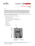
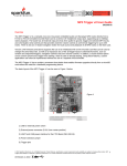
Figure 1
© 2009 SparkFun Electronics, Inc. All Rights Reserved. Product features, specifications, system requirements and availability are subject to change without notice. MP3
Trigger (WIG-09356) is a trademark of SparkFun Electronics, Inc. All other trademarks contained herein are the property of their respective owners.
1
MP3 Trigger User Guide
2009.09.17
Component Layout
The layout of the MP3 Trigger can be seen in Figure 2 below.
1) Power Select Switch
2) External Power Connector (5.5x2.1mm center positive)
3) USB Power and UART Interface for the FTDI Basic (DEV-09115)
4) USB Power Selection Jumper
5) Trigger Pins
6) 1/8" Stereo Audio Output Jack
7) Navigation Switch
8) microSD Socket
Figure 2
Supplying Power
With the Power Select Switch (1) in the EXT position, power is applied through the 2.1mm, center-positive barrel
connector (2) and is routed through the on-board regulator. 4.5V to 12V DC is the allowable input voltage range.
With the Power Select Switch in the USB position, power is applied through the USBVCC pin of the serial port
connector (3). As shipped, the USB Power selection jumper (4) routes this pin to the on-board voltage regulator so
the same voltage range as above should be observed. If the serial interface supplies 5V DC, use this position. If the
serial interface instead provides regulated 3.3V DC, then the jumper (4) may be modified so that the USBVCC pin
bypasses the on-board regulator and supplies the MP3 Trigger with 3.3V DC directly.
Refer to the MP3 Trigger schematic diagram for further details.
© 2009 SparkFun Electronics, Inc. All Rights Reserved. Product features, specifications, system requirements and availability are subject to change without notice. MP3
Trigger (WIG-09356) is a trademark of SparkFun Electronics, Inc. All other trademarks contained herein are the property of their respective owners.
2
MP3 Trigger User Guide
2009.09.17
Basic Operation
Simply transfer desired MP3 files onto a microSD flash card using a PC. The MP3 Trigger currently supports SD
media formatted with the FAT16 file structure. Most microSD cards of 2GB or less are pre-formatted with FAT16.
Cards larger than 2G, and smaller cards formatted with FAT32, will need to be reformatted to work with the MP3
Trigger.
The MP3 Trigger does not currently support hot-swapping of the microSD Card. While this will not damage anything,
the microSD media is only initialized during power up. So whenever the card is changed or updated, be sure to power
cycle the MP3 Trigger after installing the card.
When power is applied the MP3 Trigger, the on-board (green) status LED indicates the state of the installed media as
follows:
1 long blink - No FAT16 microSD media found.
1 long blink, followed by 1 short blink - microSD media found, but no MP3 files located.
Constant short blinks - Problem with MP3 Decoder hardware (diagnostic).
3 short blinks – FAT16 microSD media found, and at least one MP3 file located.
As soon as the MP3 Trigger powers up with 3 short blinks, it’s ready to go. The on-board navigation switch can be
used to play all of the tracks on the card, regardless of the filenames.
Right - Plays the next MP3 file in the directory
Left - Plays the previous MP3 file in the directory
Center - Starts/Stops the current MP3 file
Using the Trigger Inputs
The MP3 Trigger provides 7 input pins (TRIG1 – TRIG7) that can be used to trigger specific MP3 tracks on the
microSD card. Use the following file naming convention to associate a particular track with a trigger:
TRIG1: filename – TRACK001.MP3
TRIG2: filename – TRACK002.MP3
…
TRIG7: filename – TRACK007.MP3
These inputs are active low and are pulled high internally. Therefore, they can be activated either by digital outputs
from another microcontroller (such as an Arduino) or by a simple contact closure (switch) to ground. The inputs
support voltage levels of either 5V or 3.3V.
The trigger inputs are made available on the even-numbered pins of a dual row connector, and all the opposing (oddnumbered) pins are ground, making it easy to wire individual switches or contact closures directly to the MP3 Trigger
board. Refer to the MP3 Trigger schematic for details. (The ground pins are those closest to the edge of the PCB.)
Activation of a trigger immediately causes the corresponding track to play (if it exists).
© 2009 SparkFun Electronics, Inc. All Rights Reserved. Product features, specifications, system requirements and availability are subject to change without notice. MP3
Trigger (WIG-09356) is a trademark of SparkFun Electronics, Inc. All other trademarks contained herein are the property of their respective owners.
3
MP3 Trigger User Guide
2009.09.17
Installing a 14-pin dual-row header allows shunt jumpers to be installed on the trigger inputs to automatically
sequence and loop tracks on power-up as follows:
When a triggered track reaches the end, the MP3 Trigger looks to see if any trigger inputs are active, and will
automatically start another track if so. If only the same trigger is active, then that track will restart (loop). If other
triggers are active, the MP3 Trigger will always start the next higher trigger track, wrapping back to TRIG1 after
TRIG7.
This, combined with the fact that the MP3 Trigger will automatically start the lowest numbered active trigger on power
up, means that by installing shunt jumpers on the TRIG1 – TRIG7 inputs, the MP3 Trigger can be set to automatically
sequence and loop from 1 to 7 tracks on power up with no externally programming or control required.
Serial Control Protocol
The MP3 Trigger comes with a full duplex 3.3-5V serial TTL interface that allows for control of all the MP3 tracks (up
to 256) on the microSD card as well as volume. You can use our FTDI Basic (DEV-09115) or connect to any serial
interface that uses the format: 38.4Kbps, 8-bits, 1-start, 1-stop, no parity, flow control = none. Note that power can be
supplied to the MP3 Trigger by the FTDI Basic by placing the Power Select Switch in the USB Position.
All commands to the MP3 Trigger are 1 or 2 bytes in length.
1-byte commands are upper case ASCII characters.
2-byte commands start with an ASCII character. Those starting with an upper case character use
an ASCII value (‘0’ – ‘9’) as the second byte. (These commands can be typed on a keyboard.) 2byte commands starting with a lower case character require a binary value (0 – 255) as the
second byte.
Bytes sent to the MP3 Trigger are not echoed. If echoing is required, set your terminal program to echo locally.
Command Summary:
Command: Navigation – Start/Stop
Number of bytes: 1
Command byte: ‘O’
Data byte: none
Comments: This command performs the same function as pushing the on-board nav switch center position. If the
current track is playing, it stops. If the current track is stopped, it will restart from the beginning
Command: Navigation – Forward
Number of bytes: 1
Command byte: ‘F’
Data byte: none
Comments: This command performs the same function as pushing the on-board nav switch right position. The next
MP3 track in the directory will be started.
Command: Navigation – Reverse
Number of bytes: 1
Command byte: ‘R’
Data byte: none
Comments: This command performs the same function as pushing the on-board nav switch left position. The
© 2009 SparkFun Electronics, Inc. All Rights Reserved. Product features, specifications, system requirements and availability are subject to change without notice. MP3
Trigger (WIG-09356) is a trademark of SparkFun Electronics, Inc. All other trademarks contained herein are the property of their respective owners.
4
MP3 Trigger User Guide
2009.09.17
previous MP3 track in the directory will be started.
Command: Trigger (ASCII)
Number of bytes: 2
Command byte: ‘T’
Data byte: N = ASCII ‘1’ through ‘9’
Comments: If it exists, the track with the filename “TRACK00N.MP3” will be started, where N is the data byte.
Command: Trigger (binary)
Number of bytes: 2
Command byte: ‘t’
Data byte: n = 1 to 255
Comments: If it exists, the track with the filename “TRACKNNN.MP3” will be started, where NNN is the ASCII
equivalent of the data byte n.
Command: Play (binary)
Number of bytes: 2
Command byte: ‘p’
Data byte: n = 0 to 255
Comments: If it exists, the nth track in the directory will be played. The total number of available tracks in the
directory can be retrieved using Status Request command below.
Command: Set Volume (binary)
Number of bytes: 2
Command byte: ‘v’
Data byte: n = 0 to 255
Comments: The VS1053 volume will be set to the value n. Per the VS1053 datasheet, maximum volume is 0x00,
and values much above 0x40 are too low to be audible.
Command: Status Request (ASCII)
Number of bytes: 2
Command byte: ‘S’
Data byte: N = ASCII ‘0’ through ‘1’
Comments: If N = ‘0’, the MP3 Trigger will respond with a version string. If N = ‘1’, the MP3 Trigger will respond with
the total number of tracks on the installed microSD card, in ASCII. Both responses will be preceded by the ‘=’
character.
MP3 Trigger Outgoing Message Summary:
The MP3 Trigger sends the following ASCII messages:
‘X’: When the currently playing track finishes.
‘x’: When the currently playing track is cancelled by a new command.
‘E’: When a requested track doesn’t exist (error).
In response to a Status Request Command, data byte = ‘0’, the MP3 Trigger sends an 18-byte version string: e.g.
“=MP3 Trigger v1.00”
In response to a Status Request Command, data byte = ‘1’, the MP3 Trigger sends the number of MP3 tracks on the
currently installed microSD card: e.g. “=14”
© 2009 SparkFun Electronics, Inc. All Rights Reserved. Product features, specifications, system requirements and availability are subject to change without notice. MP3
Trigger (WIG-09356) is a trademark of SparkFun Electronics, Inc. All other trademarks contained herein are the property of their respective owners.
5