1
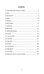
user manual
The SpeakUp is a speech recognition click™ board. You can
set it up to recognize over 200 different voice commands
and have the on-board MCU carry them out instantly.
TO OUR VALUED CUSTOMERS
I want to express my thanks to you for being interested in our products and for having
confidence in MikroElektronika.
The primary aim of our company is to design and produce high quality electronic products
and to constantly improve the performance thereof in order to better suit your needs.
Nebojsa Matic
General Manager
The STM32® and Windows® logos and product names are trademarks of ST microelectronics® and Microsoft® in the U.S.A. and other countries.
Page 2
Table of Contents
1. Introduction
4
8.2. Getting Started
14
2. Applications
5
8.3. Creating a new project 15
3. Package Contains
6
8.4. New Voice Command
16
4, How to use it?
7
8.5. Configuring Project Settings
18
5. Tech Specs
8
8.6. Assigning An Action
20
6. Schematics
9
8.7. Uploading Project
22
8.8. Exporting Constants
23
7. How It Works?
10
SpeakUp Firwmware Algorithm
11
9. Direct Configuration
24
8. Configuration Through Software
12
10. Recording Tips
25
13
11. Examples
26
8.1. Typical Workflow
Page 3
1. Introduction
The SpeakUp is a speaker dependent speech
recognition click board with standalone
capabilities. You can set it up to recognize over
200 voice commands and have the onboard
STM32F415RG MCU carry them out. It works
by matching sounds with pre-recorded
commands. Sound is received through an
onboard microphone and then processed by
a VS1053 IC with a built in stereo-audio
codec. The SpeakUp comes with
a dedicated software tool for
easy configuration. The board is
lined with 12 user programmable GPIOs
for standalone functionality. It also carries a
standard mikroBUS™ host socket.
Easy
configuration
Over 200
commands
Ultra fast
operation
Page 4
Standalone
mode
2. Applications
Wouldn't you rather issue verbal commands and have your machines comply, instead of pressing keys, pushing buttons and flipping
switches all the time? There's a wide range of applications for the SpeakUp.
Command your lights, doors and home appliances.
Create voice commanded remotes for TVs or media centers.
Reduce complexity and cost of control interfaces.
When doing something with both hands and voice command is the only option.
Page 5
3. Package Contains
Package dimensions:
L 70mm, W 60mm, H 30mm
Box
Package weight:
~40g
User manual
1x8 headers
Recycle Bin
document
SpeakUp click™ board
Page 6
4. How To Use It?
Before using your click™ board on your target platform, make sure to solder 1x8 male headers to both left and right side of the board.
Two 1x8 male headers are included with the board in the package.
1. Prepare it
2. Configure it
3. Use it
Turn the board upside down so that
the bottom side is facing you upwards.
Place shorter pins of the header into
the appropriate soldering pads. Turn the
board upward again. Make sure to align the
headers so that they are perpendicular to
the board, then solder the pins carefully.
Now you need to train your SpeakUp to
obey your commands. Plug in the board
to your PC through USB cable. Configure
it using the free software (see page 12).
Alternatively you can configure the board
directly using the on-board buttons (see
page 24).
The SpeakUp now understands your
commands. Connect relays, motors or
other electronic actuators directly to
SpeakUp’s GPIO pins. Alternatively plug
the SpeakUp into any board or shield
carrying a mikroBUS™ socket. You can now
control your devices with your voice.
Page 7
5. Tech Specs
10.30 mm
405.50 mils
Line out pads
USB connector
Microphone
Audio jack
12 GPIOs
(user programmable)
Microcontroller
(STM32415RG)
57.15 mm
2550 mils
Audio Codec
(VS1053)
Signal LEDs
mikroBUS
connector
Push-buttons
JTAG connector
25.40 mm
1000 mils
Along with its key components, the SpeakUp packs other useful bits like two buttons for recording or deleting voice commands manually, while
three signal LEDs give recognition feedback and indicate power.
Page 8
6. Schematics
C3
C4
C5
C6
100nF 100nF 100nF 100nF 100nF
2.2uF
D1
10uF
PMEG3010ER
U3
1
VCC-3.3V
IN OUT
2
C34
GND
3
EN ADJ
2.2uF
5
AP7331-ADJ
R35
C43
10uF
100K
R36
27K4
GND
3
VCC-1.8V
R33
4
5
IN OUT
4
EN ADJ
R34
287K
R37
39K
AP7331-ADJ
2.2uF
C2
U4
1
2
C35
VCC-3.3V
C1
C33
VCC-3.3V
VCC-USB
R38
OR
C7
1K
VCC-3.3V
R39
10K
LD2-PC12
LD1-PB2
LD2
R2
4K7
LD1
R1
4K7
10
C10
C11
C12
47nF
10nF
10nF
R28
10K
RST#
SPI1-CS#
SPI1-SCLK
SPI1-MISO
SPI1-MOSI
C44
100nF
PWM
INT
TX
RX
SCL
SDA
+5V
GND
MIKROBUS DEVICE CONN.
R30
10K
48
47
46
45
44
43
42
41
40
39
38
37
VCC-3.3V
IO7-PA2
IO8-PA1
IO9-PA0
IO10-PC2
IO11-PC1
IO12-PC0
PWM
INT
UART3-TX
UART3-RX
I2C1-SCL
I2C1-SDA
HD2
1
2
3
4
5
6
7
8
SW1-PB10
R23
10K
R24
C32
100nF
10uF
C9
3.3nF
R4
100K
R
G
L
R11
100K
VCC-3.3V
36
35
34
33
32
31
30
29
28
27
26
25
R16
1K
R19 27
MP3-MISO
MP3-MOSI
MP3-SCLK
C14 100pF
MICP
MICN
C16 100pF
R18
1K
C15
100PF
C41
C42
10uF
10uF
VCC-3.3V
2
5
6
3
4
1
R20
1K
CN2
SJ- 43516-SMT
R21
1K
MIC1
R22
10K
1
MICROPHONE
1M
X1
SW1
C18
18pF
VCC-3.3V
SW2-PD2
10uF
C39
VCC-USB
C20
100nF
R31
10K
C38
2
VCC-3.3V
R25
10K
VS1053
GPIO4
GND
GPIO1
GPIO0
XTEST
CVDD3
SO
SI
SCLK
TX
RX
GPIO5
GPIO
MP3-DREQ
MP3-MOSI
MP3-MISO
MP3-SCLK
MP3-CS#
XDCS/BSYNC
IOVDD1
VC0
DGND1
XTAL0
XTAL1
IOVDD2
DGND2
DGND3
DGND4
XCS
CVDD2
R17
10K
MICP/LN1
MICN
XRESET
DGND0
CVDD0
IOVDD0
CVDD1
DREQ
GPIO2
GPIO3
GPIO6
GPIO7
3.3nF
C8
MP3-CS#
IO2-PB0
IO1-PB1
LD1-PB2
SW1-PB10
R29
10K
AN
RST
CS
SCK
MISO
MOSI
+3.3V
GND
1
2
3
4
5
6
7
8
9
10
11
12
13
14
15
16
17
18
19
20
21
22
23
24
IO6-PC9
IO5-PC8
IO4-PC7
U2
MICP
MICN
MP3-RST#
MP3-DCS
TMS-SWDIO
USB-D_P
USB-D_N
USB-ID
USB-DET
LN2
AGND3
LEFT
AVDD2
RCAP
AVDD1
GBUF
AGND2
AGND1
RIGHT
AVDD0
AGND0
C13
2.2uF
48
47
46
45
44
43
42
41
40
39
38
37
36
35
34
33
C17
2.2uF
VCC-3.3V
R15
10K
R10 470
10
R7
10
R8
10
R14
10
10
R13
R9
R6 470
10
R5
R12
RIGHT
LEFT
GBUF
VCC-1.8V
GPIO
STM32F415RG
VDD
VCAP2
PA13
PA12
PA11
PA10
PA9
PA8
PC9
PC8
PC7
PC6
PB15
PB14
PB13
PB12
17
18
19
20
21
22
23
24
25
26
27
28
29
30
31
32
IO1-PB1
IO2-PB0
IO3-PA3
IO4-PC7
IO5-PC8
IO6-PC9
VDD
VSS
PB9
PB8
BOOT0
PB7
PB6
PB5
PB4
PB3
PD2
PC12
PC11
PC10
PA15
PA14
VBAT
PC13
PC14
PC15
PH0
PH1
NRST
PC0
PC1
PC2
PC3
VSSA
VDDA
PA0
PA1
PA2
IO3-PA3
1
2
3
4
5
6
7
8
IO9-PA0
IO8-PA1
IO7-PA2
1
2
3
4
5
6
7
8
9
10
11
12
13
14
15
16
PA3
VSS
VDD
PA4
PA5
PA6
PA7
PC4
PC5
PB0
PB1
PB2
PB10
PB11
VCAP1
VDD
RST#
IO12-PC0
IO11-PC1
IO10-PC2
HD1
VCC-3.3V
U1
JTAG
VCC-3.3V
RIGHT
GBUF
LEFT
VCC-3.3V
64
63
62
61
60
59
58
57
56
55
54
53
52
51
50
49
2 TMS-SWDIO
4 TCK-SWCLK
6
8
10
RST#
MP3-DREQ
SW2-PD2
LD2-PC12
UART3-RX
UART3-TX
MP3-DCS
TCK-SWCLK
I2C1-SDA
I2C1-SCL
VCC-3.3V
SPI1-CS#
SPI1-SCLK
SPI1-MOSI
SPI1-MISO
1
3
5
7
9
CN4
MP3-RST#
INT
PWM
1uF
VCC-3.3V
12.288MHz
USB-DET
USB-D_N
USB-D_P
USB-ID
C19
18pF
C21
100nF
VCC-3.3V
SW2
C40
10uF
VCC-1.8V
C22
100nF
C23
100nF
Page 9
C24
100nF
C25
100nF
C26
100nF
C27
100nF
R26 220
C28
100nF
C29
100nF
C30
100nF
C31
100nF
VCC-3.3V
R3
2K2
LD3
FP1
FERRITE
CN3
1
2
3
4
5
VBUS
DD+
ID
GND
USB MINIB
1
2
3
HD3
7. How It Works?
What gives the SpeakUp its speech recognition capabilities is the firmware we developed for the on-board MCU. It’s based on the DTW
algorithm, which makes it decisive, it turns your talk into action almost instantly.
Input:
Sound is received through an on-board microphone. There’s also a 3.5mm jack for
connecting an external microphone.
Between the mic and the MCU sits a VS1053 IC with a
built in stereo audio codec to process the raw signal.
Output:
After the processed sound has been forwarded to the STM32F415RG MCU that interprets the voice
command, there are two output options which can be utilized at the same time or separately:
STANDALONE MODE:
On-board MCU directly controls
external devices using 12 user
programmable GPIOs
CLICK™ MODE:
Sends index of the matched voice
command to a selectable interface:
USB or UART.
Page 10
SpeakUp Firmware Algorithm
The main goal of a speech recognition system is to substitute a human listener, although it is very difficult for an artificial system to achieve
the flexibility offered by human ear and human brain. The work principle of speech recognition systems is roughly based on the comparison of
input data to prerecorded patterns. These patterns can be arranged in the form of phoneme or word. By this comparison, the pattern to which
the input data is most similar is accepted as the symbolic representation of the data. It is very difficult to compare raw speech signals directly.
Because the intensity of speech signals can vary significantly, a preprocessing on the signals is necessary. This preprocessing is called Feature
Extraction.
First, short time feature vectors are obtained from the input speech data, and then these vectors are compared to the patterns classified
prior to comparison. The feature vectors extracted from speech signal are required to best represent the speech data, to be in size that can be
processed efficiently, and to have distinct characteristics.
The SpeakUp Firmware uses Dynamic Time Warping (DTW) algorithm - word-based, isolated word, speaker dependent and template matching
algorithm :
In the word based speech recognition the smallest recognition unit is a word
In the isolated word recognition, words that are uttered with short pauses are recognized,
Speaker dependent reference patterns are constructed for a single speaker,
Template matching algorithm is a form of pattern recognition. It represents speech data as sets of feature/parameter vectors called
templates. Each word or phrase in an application is stored as a separate template. The input speech is then compared with stored
templates and the stored template most closely matching the incoming speech pattern is identified as the input word or phrase.
Page 11
8. Configuration Through Software
The SpeakUp software configuration tool is a free PC
application for configuring the SpeakUp click board. With it, you
can configure the board to recognize over 200 different voice
commands and have the on-board MCU carry them out instantly.
You can download the software from the following link:
http://www.mikroe.com/downloads/get/2077/
speakup_app.zip
The software is designed with ease of use and simplicity in
mind. The UI is based on tabs and drop-down menus requiring
no programming skills to use.
Still, it has all the essential features and options that give you
full control of the set-up process.
Page 12
8.1. Typical workflow
Create a new
project or open
existing manually
Launch the app
New project created
or last one loaded
automatically
First time you launch the app a new project is
created automatically. Otherwise, the last project
you were working on will open.
Add or Edit
voice commands
Everything OK?
YES
Assign actions
Upload
Close
Page 13
NO
Adjust
Settings
8.2. Getting Started
Connect the SpeakUp click board to the computer via the USB
cable. It will be recognized as a USB Human Interface Device (HID)
in the Device Manager of the Control Panel.
Once you connect the SpeakUp to your computer you’re just a few
clicks away from configuring it. The set-up process is dead simple.
Launch the application, and it will lead you through the initial
steps of recording and assigning commands.
Page 14
Ambient Noise Detection
After the successful connection, the SpeakUp click™ board
will perform ambient noise detection and calibrate itself. The
process lasts about 10 seconds. It’s done when the red signal
LED turns off. After that the board is ready for recording voice
commands. You can set custom calibration parameters for
any subsequent usage in the Project Settings (see page 18).
8.3. Creating A New Project
To create a new project, press the Create New Project button from the main toolbar
of the SpeakUp software.
A new window will open, where you can enter your project’s name and destination
folder (if the destination folder doesn’t exist, the software will prompt you to create it).
To finish project creation after inputting the required information, press the Create
button.
Alternatively, you can choose to open the settings menu as soon as you create a
project, by checking the appropriate box.
Page 15
8.4. New Voice Command
Add a voice command
Record it
Stay within the time limit
Hear it back
To record a new voice
command, press the Add New
Voice Command button.
A New Voice Comand dialog
window will appear. Press the
Record button.
The length of the recording
is set in the Project Settings
window (see page 18).
The recorded command will be
played back automatically, so
you can make sure it’s OK.
Page 16
Name it and save it
You’re done!
Troubleshoot
If you’re satisfied with the
recording, enter a name for
your command and click the
Save & Close button.
The recorded command will
appear as a new tab. You can
play it back, edit or delete it
anytime.
If the SpeakUp fails to detect a voice command, your
surrounding might be too noisy. Try again by speaking a bit
louder. If it still doesn’t work, launch Settings and adjust the
Noise treshhold.
Page 17
8.5. Configuring Project Settings
To configure project settings, press the Open Settings Window button and the
Settings window will open.
General Settings
In the General Settings you can configure the SpeakUp’s functionality:
Acceptance threshold: This is the parameter you should adjust to define
how closely your delivery has to match your pre-recorded command. At lower
values, you’ll have to deliver the command precisely the way you recorded
it. At higher values the matching doesn’t have to be so precise, but this
increases the probability that the SpeakUp will pick up irrelevant speech and
interpret it as a command. You should be able to reach the sweet spot value
through some trial & error.
Recording timeout: Timeframe in which the SpeakUp click board expects
recording input after the record button is being pressed. User can choose
between 5, 10 and 15 seconds timeframes.
Word Length: Length of the voice command being recorded, in seconds. Can
be 1, 1.5, 2, 2.5 and 3 seconds
Page 18
Noise level: Minimal sound volume level that can trigger a
voice command recognition. Lower values require quieter
pronunciation, resulting in higher noise/hiss sensitivity.
On the contrary, higher level values require louder
pronounciation and they are less sensitive to noise/hiss.
We recommend that you keep auto detection enabled. That
way the SpeakUp Click board will measure the noise level,
and perform noise calibration automatically. Auto detection
can last a bit longer, usually around 10 seconds. Sudden
Pin Aliases And Initial Pin States
In this section, you can rename GPIO pins according
to your needs and set their starting conditions. The
new GPIO pin aliases will be applied in the main
window too. Set the corresponding initial GPIO pin
state in the Initial Pin States section. Condition can
be either low (logical 0) or high (logical 1).
Page 19
changes in sound levels will lengthen the time of calibration
and will result in improper sound level values.
Notify master: Notifies the master (MCU or PC) when the
voice command is recognized by sending a 16-bit index
number of voice command via chosen communication
interface (UART or USB).
Data rate: Sets the speed used for sending data to the
master (MCU or PC).
8.6. Assigning An Action
When a new command is recorded, it is time to assign it an action. The action will be
performed when the voice command is recognized. Also, a 16-bit index number of the
voice command will be sent via chosen communication interface (UART or USB) .
There are five types of action that can be assigned :
NONE: When this option is selected, no action will be performed on the
corresponding GPIO pin upon voice command matching.
ON: When this option is selected, a corresponding GPIO pin will be set to logical
high state upon voice command matching.
OFF: When this option is selected, a corresponding GPIO pin will be set to logical
low state upon voice command matching.
TOGGLE: When this option is selected, a corresponding GPIO pin state will be
toggled upon voice command matching.
PULSE: When this option is selected, a train of pulses will be sent to the
corresponding GPIO pin upon voice command matching.
Page 20
Pulse parameters
The pulse parameters can be set in the Pulse Parameters window (click on the Edit
pulse parameters icon Edit pulse parameters to open it) :
A period (T) is the time it takes for a signal to complete a single cycle (sum of the
high state and low state time periods).
Duty ratio (D) is the percentage of T in which a signal is active, i.e. ratio of the
high state period and a complete period.
N is the number of times the pulse is repeated.
Thus, a 60% duty cycle means the signal is ON 60% of the time period but OFF 40%
of the time period.
Page 21
8.7. Uploading Project
When you’re finished recording and configuring voice commands, it is time to upload
the project to the SpeakUp click™ board. This is done via the Upload Project button.
You can monitor the upload process in the Toolbar.
After it’s done, an appropriate message will be displayed in the Status Bar.
Page 22
8.8. Exporting Constants
Each recorded voice command is given an index number which is sent to the
host MCU. You can export voice command names and their indexes as constants.
The exported document will be in the form of a source file (in any of the three
languages), as shown below.
mikroC
mikroBasic
mikroPascal
/*
This file is generated by SpeakUp Software.
It containts voice commands constants.
Creation date: 4/3/2014 Creation time: 11:20:09 AM
Name: Turn ON Program A Index: 0 Length: 0.0 s
Description: Turns on Program A
*/
const VCMD_TURN_ON_PROGRAM_A = 0;
/*
Name: Turn ON program B Index: 1
Description: Turns on Program A
Length: 0.0 s
*/
const VCMD_TURN_ON_PROGRAM_B = 1;
Page 23
9. Direct Configuration
You can perform some basic configuration directly on the SpeakUp without using the software. Different combinations of button presses will
allow you to record, re-record or erase commands. You’ll get feedback from the on-board LEDs. However you won’t be able to assign specific
actions with this method.
On-board push-buttons
On-board LEDs
Use push-buttons to operate the board:
Two indicator LEDs provide the following signals:
1
Push-button 1 - To record your voice command,
press and hold the button while speaking. You must
stay within the time limit for each command (default
settings: 1 second). You can also record multiple
commands at once by pronouncing them one by one
while keeping the button pressed. Just make sure to
wait for the red LED to flash between pronouncing
subsequent commands. Proceed in this way for as
many commands as you need. Each command will be
assigned a unique index.
Amber LED - the board is ready for recording
or listening.
Push-button 2 - If you press it for more than 2
seconds, all recorded voice commands will be erased.
2
Red LED - the board is perfoming an operation.
When the voice command is recognized,
both LEDs are lit for a half a second.
Standalone mode default settings:
1
2
1
If both push-buttons are pressed for more
than 2 seconds, the SpeakUp click board will reset.
Page 24
2
Acceptance Threshold: 15
Recording Timeout: 5s
Word Length: 1s
Noise Level: Auto
Notify Master: USB
10. Recording Tips
Here are some general recording Tips :
For better recording results, it is necessary to provide conditions with lowest amounts of ambient noise and speaker distance from
the microphone in the range from 10 to 20cm.
If there are problems with the voice command detection, please record it several times due to the pronounciation diversity.
It is mandatory to play back the recorded voice command in order to hear if some ambient noise was recorded also.
Because of this, it is recommended that the SpeakUp click™ board is placed on a surface that doesn’t transfer mechanical vibrations.
This is a speaker dependent system. If there are more users, each person should record voice commands separately, due to the
pronounciation diversity.
Number of voice commands that can be recorded depend on their lengths, typically more than 200 for the voice command length
of 1 second.
Please keep in mind that the recording is performed by the SpeakUp click™ board, not the computer, so there is no need to connect
an external microphone to the computer.
Page 25
11. Examples
SpeakUp has a world of applications. It’s up to your imagination to come up with the coolest ideas. Here’s a hint or two:
Use SpeakUp on top of the Pi click Shield to command XBMC
Home Media Center on Raspberry Pi®. It’s a great a replacement
for a mouse and a keyboard.
Replace your lamp switch with a SpeakUp click and a relay.
Tell your light to turn ON or OFF if your hands are busy doing
something important.
Page 26
DISCLAIMER
All the products owned by MikroElektronika are protected by copyright law and international copyright treaty. Therefore, this manual is to be treated as any
other copyright material. No part of this manual, including product and software described herein, may be reproduced, stored in a retrieval system, translated or
transmitted in any form or by any means, without the prior written permission of MikroElektronika. The manual PDF edition can be printed for private or local use,
but not for distribution. Any modification of this manual is prohibited.
MikroElektronika provides this manual ‘as is’ without warranty of any kind, either expressed or implied, including, but not limited to, the implied warranties or
conditions of merchantability or fitness for a particular purpose.
MikroElektronika shall assume no responsibility or liability for any errors, omissions and inaccuracies that may appear in this manual. In no event shall MikroElektronika,
its directors, officers, employees or distributors be liable for any indirect, specific, incidental or consequential damages (including damages for loss of business
profits and business information, business interruption or any other pecuniary loss) arising out of the use of this manual or product, even if MikroElektronika has
been advised of the possibility of such damages. MikroElektronika reserves the right to change information contained in this manual at any time without prior
notice, if necessary.
HIGH RISK ACTIVITIES
The products of MikroElektronika are not fault – tolerant nor designed, manufactured or intended for use or resale as on – line control equipment in hazardous environments requiring fail – safe performance, such as in the operation of nuclear facilities, aircraft navigation or communication systems, air traffic
control, direct life support machines or weapons systems in which the failure of Software could lead directly to death, personal injury or severe physical or
environmental damage (‘High Risk Activities’). MikroElektronika and its suppliers specifically disclaim any expressed or implied warranty of fitness for High
Risk Activities.
TRADEMARKS
The MikroElektronika name and logo, the MikroElektronika logo, the click boards™ are trademarks of MikroElektronika. All other trademarks mentioned herein are
property of their respective companies.
All other product and corporate names appearing in this manual may or may not be registered trademarks or copyrights of their respective companies, and are only
used for identification or explanation and to the owners’ benefit, with no intent to infringe.
Copyright © 2014 MikroElektronika. All Rights Reserved.
Page 27
If you want to learn more about our products, please visit our website at www.mikroe.com
If you are experiencing some problems with any of our products or just need additional
information, please place your ticket at www.mikroe.com/support/
If you have any questions, comments or business proposals,
do not hesitate to contact us at [email protected]