1
InvenSense Inc.
1197 Borregas Ave., Sunnyvale, CA 94089 U.S.A.
Tel: +1 (408) 988-7339 Fax: +1 (408) 988-8104
Website: www.invensense.com
Document Number: AN-EMAPPS-0.0.6
Revision: 1.0
Release Date: 06/27/2014
Motion Driver 6.1 – User Guide
CONFIDENTIAL & PROPRIETARY
PRELIMINARY
Document Number: AN-EMAPPS-0.0.6
Motion Driver 6.0 – User Guide
Revision: 1.0
Release Date: 06/27/2014
Table of Contents
1
REVISION HISTORY ...................................................................................................................................3
2
PURPOSE ....................................................................................................................................................4
3
BEFORE YOU START ................................................................................................................................4
4
MOTION DRIVER 6.0 FEATURES ..............................................................................................................4
5
SELECTING THE MCU ...............................................................................................................................5
6
CONNECTING THE HARDWARE ..............................................................................................................5
7
MOTION DRIVER 6.0 FIRMWARE PACKAGE ..........................................................................................6
8
INTEGRATING MOTION DRIVER 6.0 ........................................................................................................6
9
INITIALIZATION APIS .................................................................................................................................9
10 THE ORIENTATION MATRIX .....................................................................................................................9
11 INTERRUPTS HANDLING ........................................................................................................................10
12 DMP - DIGITAL MOTION PROCESSOR™ ..............................................................................................10
12.1
DMP INTIALIZATION ...........................................................................................................................10
12.2
DMP FEATURES ................................................................................................................................10
12.3
DMP FIFO OUTPUT ..........................................................................................................................11
13 INVENSENSE HARDWARE SELF-TEST .................................................................................................11
14 CALIBRATION DATA AND STORAGE ....................................................................................................12
14.1
FACTORY LINE CALIBRATION...............................................................................................................12
14.2
SAVING AND LOADING CALIBRATION DATA ..........................................................................................13
15 INTEGRATING THE MPL LIBRARY.........................................................................................................13
16 LOW POWER ACCEL MODE AND MOTION INTERRUPT MODE FOR MPU6500/MPU9250 ..............14
17 COMPILER SPECIFIC SETTING ..............................................................................................................14
CONFIDENTIAL & PROPRIETARY
2 of 14
PRELIMINARY
Document Number: AN-EMAPPS-0.0.6
Motion Driver 6.0 – User Guide
Revision: 1.0
Release Date: 06/27/2014
1
Revision History
Revision Date
Revision
Description
06/27/2014
1.0
Initial Release
07/17/2014
1.1
Expanding information for the ARM MPL libaries
CONFIDENTIAL & PROPRIETARY
3 of 14
PRELIMINARY
Document Number: AN-EMAPPS-0.0.6
Motion Driver 6.0 – User Guide
Revision: 1.0
Release Date: 06/27/2014
2
Purpose
Motion Driver is an embedded software stack of the sensor driver layer that easily configures and leverages
many of the features of the InvenSense motion tracking solutions. The motion devices supported are
MPU6050/MPU6500/MPU9150/MPU9250. Many of the features of the hardware and the on board Digital
Motion Processor (DMP) are encapsulated into modular APIs which can be used and referenced.
Motion Driver is designed as a solution which can be easily ported to most MCUs. With the release of the
Motion Driver 6.0 it includes a 9-axis solution for ARM MCUs and the TI-MSP430. 6-axis only solutions
should continue to reference the Motion Driver 5.1.2 for easier understanding of the software.
This document highlights the fundamental procedure and choices you will encounter when starting to
develop an embedded project using the Motion Driver 6.0 as reference. We will go into some of the more
details topics like programming the DMP, calibration, and self test.
3
Before you start
Please read the Motion Driver 6.0 Getting Started Guide and the Motion Driver 6.0 Features Guide. It is
recommended that customers bring up the Motion Driver 6.0 on one of the ported platforms (TI-MSP430 or
IAR ARM) so they better can understand the code and features. After understanding the features it will make
it much easier to port it to your ecosystem.
4
Motion Driver 6.0 Features
This is a quick overview on the MD6 features.
DMP Features:
o
3/6 Axis Low Power Quaternions
o
Tap, Orientation, and Pedometer Gesture Detections
MPL Algorithms:
o
Run Time Gyro Calibration
o
Run Time Gyro Temperature Compensation
o
Run Time Compass Calibration
o
Run Time Magnetic Disturbance Rejection
o
3/6/9 Axis Sensor Fusion
Hardware Features:
o
Factory Calibration
o
Factory Self Test
o
Saving and Loading Sensor States
o
Low Power Accel Mode
o
Low Power Motion Interrupt Mode
o
Register Dump
CONFIDENTIAL & PROPRIETARY
4 of 14
PRELIMINARY
Document Number: AN-EMAPPS-0.0.6
Motion Driver 6.0 – User Guide
Revision: 1.0
Release Date: 06/27/2014
5
Selecting the MCU
With every embedded system, the functionality and performance is dependent on the MCU selected. Cost,
low power, speed, tool chains, and processing are all factors to consider. For the MPU device if you are
planning to use the InvenSense Motion Driver 6.0 software here are some things to consider.
Flash and RAM Size : Flash and RAM size is dependent on code optimization, compilers, what
features you want to use, and what other components are in your system. In general though, MD6.0
requires you can need reserve the following amount of Flash and RAM. Keep in mind this will only be
for the motion driver and not for other possible functionalities.
o
o
o
8-bit MCU – 256K and 64K
16-bit MCU – 128K and 32K
32-bit MCU – 68K and 16K (No Optimization, 64K and 10K with optimization)
Again since depending size is very dependent on compiler and compiler settings, customers should
spend time to determine what size flash and RAM is needed for their applications.
6
Long long math support : The MPL library requires support for long long (64-bit) math. You will
need to make sure if you are using the MPL library your tool chains can support this. Usually 8051
MCUs cannot support such mathematical calculations. If the tool chain does not support long long
math, you can still use the DMP to get 6-axis fusion.
Interrupts : The MPU device can provide an interrupt for various functions from low power gesture
recognition or data ready interrupts. While not required for the system to use the MPU interrupt, if
you are planning to use it, then you must reserve a GPIO pin which has wakeup capabilities.
Sampling Rate : Sensor fusion requires large computational power from the MCU. This plays into
how much processing is possible per sample and limits your sampling rate. For example the TI 16-bit
MSP430 with the Motion Driver should be limited to 100Hz sampling rate if the MCU is doing the full
9-axis fusion. Anything over 100Hz sampling rate the MSP430 start missing data. Higher end 32-bit
MCUs can usually achieve 200Hz sensor fusion if there are no other large computational
functionality required in the system. This sample rate can be increased if you offload the processing
onto the DMP.
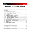
Connecting the Hardware
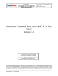
After selecting the MCU most likely you will have a MCU evaluation kit or your own PCB board. To connect
the MPU device to the MCU board for evaluation, you can obtain an InvenSense MPU evaluation board
through InvenSense.com. MPU6050, MPU6500, MPU9150, and MPU9250 are all available.
Eval Board
CONFIDENTIAL & PROPRIETARY
5 of 14
PRELIMINARY
Document Number: AN-EMAPPS-0.0.6
Motion Driver 6.0 – User Guide
Revision: 1.0
Release Date: 06/27/2014
You will need to connect the following pins from the evaluation board to the MCU board
VDD and VDD_IO (pin 23): Depending on the MPU device this would be a 3V or a 1.8V (see device
spec)
SDA and SCL (pins 20, 22): I2C pins
GND (pins 15 or 17): Connect to ground
INT (pin 7): Connect to GPIO for interrupts (optional but needed if using Invensense software)
The pin outs of the InvenSense evaluations boards are the same.
To confirm your hardware setup and also the basic I2C functionality, start by reading the MPU device’s
whoami register and confirm you are getting the correct device ID. For the MPU series the I2C address is
0x68 while the device ID is all different for the different parts so please check the specs. After hardware
confirmation, we can continue with the software integration.
7
Motion Driver 6.0 Firmware Package
The Motion Driver 6.0 release firmware contains the following folders:
8
core\driver : This folder contains the InvenSense drivers layer for the MPU devices as well as
the MCU specific drivers
simple_apps\msp430\mllite_test.c or src\main.c : The main function and main loop for the project
application. Customers can use this code as a reference to integrate the driver functions
into their project.
core\mllite : This folder contains the MPL data processing functions that store the received
sensor data and processes the data.
core\mpl : Contains the InvenSense Proprietary MPL library – a library containing advanced
algorithms for sensor fusion and run-time calibrations.
core\eMPL-hal : This folder contains the files that provide same the sensor data conversion such as
linear acceleration.
Integrating Motion Driver 6.0
Embedded MD6 consists of the following components that are required to be integrated on the target
hardware platform:
1) Driver
2) Motion Processing Libraries
3) Sample HAL
CONFIDENTIAL & PROPRIETARY
6 of 14
PRELIMINARY
Document Number: AN-EMAPPS-0.0.6
Motion Driver 6.0 – User Guide
Revision: 1.0
Release Date: 06/27/2014
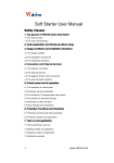
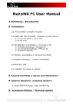
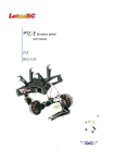
The diagram below shows the architecture of Motion Driver 6.0 and the tasks to be performed to port the
MD6 successfully to the target platform.
MAIN
Application-specific:
MPL
APIs
MPL
1. Data output (and input).
2. Client handling.
3. Power management.
Driver
APIs
No porting needed!
Driver
Layer
Platform-specific:
1.
2.
3.
4.
I2C read/write.
System clock (ms).
Hardware interrupts.
Log outputs.
1. The Invensense MD6 Driver Layer (core\driver\eMPL) consists of these files
inv_mpu.c
- the driver which can be easily ported to different embedded platforms.
inv_mpu.h
- contains the structures and prototypes for the InvenSense driver.
inv_mpu_dmp_motion_driver.c - the driver for containing the dmp image and the APIs to load
and configure the DMP.
inv_mpu_dmp_motion_driver.h – contains the prototypes and defines for the DMP features
dmpKey.h
- Contains the defines for DMP memory locations for DMP features
dmpmap.h
- Contains the defines for DMP memory locations
The user would need to provide the following APIs to support I2C read/write functionality, system clock
access, hardware interrupts callbacks and logging corresponding to the platform on which the
MD6 is to be ported.
These functions need to be defined in inv_mpu.c and inv_mpu_dmp_motion_driver.c. Below is an
example as shown for the MSP430 platform.
#define i2c_write
#define i2c_read
#define delay_ms
#define get_ms
#define log_i
#define log_e
CONFIDENTIAL & PROPRIETARY
msp430_i2c_write
msp430_i2c_read
msp430_delay_ms
msp430_get_clock_ms
MPL_LOGI
MPL_LOGE
7 of 14
PRELIMINARY
Document Number: AN-EMAPPS-0.0.6
Motion Driver 6.0 – User Guide
Revision: 1.0
Release Date: 06/27/2014
i2c_write and i2c_read : this will need to be linked to the i2c drivers. This functions will take in 4
parameters then perform the i2c transactions
unsigned char slave_addr
unsigned char reg_addr
unsigned char length
unsigned char *data
delay_ms : this function will take in one unsigned long parameter and it will act as a delay in milliseconds
for the system
get_ms : get_ms is mainly used to get the current timestamp. Timestamp are usually an unsigned long
and in milliseconds. This function will mainly be used for the compass scheduler and also
additional information for sensor fusion data.
log_i and log_e : MPL messaging system in which it can log informational or error messages. Current
implementation packets the message and sends it out through the USB or UART for the python
client to receive. The logging code is located in the file log_msp430.c or log_stm32l.c.
Customers can change the transport method and packets to their liking.
2. MPL Library is the core of the proprietary InvenSense Motion Apps algorithms and consists of Mllite and
mpl directory. There is no porting required for MPL. You may need to include system specific header
files to support the memcpy, memset, … etc., function calls in the mllite package. The MD6 package will
include pre-compiled MPL libraries, one for the TI MSP430 platform and the other for ARM core
platforms. The ARM library has a generic library which can be linked to any ARM MCU. It also have
some pre-compiled for M3 and M4 for better optimizations.
3. The eMPL-HAL directory contains the APIs to get various data from the MPL library. The data you can
obtain are from the following APIs
int inv_get_sensor_type_accel(long *data, int8_t *accuracy, inv_time_t
*timestamp);
int inv_get_sensor_type_gyro(long *data, int8_t *accuracy, inv_time_t
*timestamp);
int inv_get_sensor_type_compass(long *data, int8_t *accuracy, inv_time_t
*timestamp);
int inv_get_sensor_type_quat(long *data, int8_t *accuracy, inv_time_t
*timestamp);
int inv_get_sensor_type_euler(long *data, int8_t *accuracy, inv_time_t
*timestamp);
int inv_get_sensor_type_rot_mat(long *data, int8_t *accuracy, inv_time_t
*timestamp);
int inv_get_sensor_type_heading(long *data, int8_t *accuracy, inv_time_t
*timestamp);
int inv_get_sensor_type_linear_acceleration(float *values, int8_t *accuracy,
inv_time_t * timestamp)
4. The main.c or mllite_test.c contains a very specific application that
Handles of sensor data processing from the MPU device
Handling input requests from the client
Power management
Initializing the MPL library, DMP, and the hardware
Handle the interrupts
CONFIDENTIAL & PROPRIETARY
8 of 14
PRELIMINARY
Document Number: AN-EMAPPS-0.0.6
Motion Driver 6.0 – User Guide
Revision: 1.0
Release Date: 06/27/2014
9
Initialization APIs
At power on the MPU device will provide sensor data in it default state. The inv_mpu.c provides a
reference API on how to initialize the MPU device with some basic configurations such as powering on
the sensors and setting the scale range and sampling rate
int
int
int
int
int
int
int
int
mpu_init(struct int_param_s *int_param)
mpu_set_gyro_fsr(unsigned short fsr)
mpu_set_accel_fsr(unsigned char fsr)
mpu_set_lpf(unsigned short lpf)
mpu_set_sample_rate(unsigned short rate)
mpu_set_compass_sample_rate(unsigned short rate)
mpu_configure_fifo(unsigned char sensors)
mpu_set_sensors(unsigned char sensors)
10 The Orientation Matrix
rd
The application also needs to define the orientation matrix for the MPU device and the 3 party compass
if present on the platform. The orientation matrix will reconfigure the physical hardware sensor axis to the
to the device coordinates. A wrong configuration will get you inaccurate results from the sensors data. For
more information on how the matrix should be defined please reference the Orientation Matrix
Transformation chart.pdf.
The matrixes will be pushed into both the MPL library and DMP for fusion calculations.
struct platform_data_s {
signed char orientation[9];
};
/* The sensors can be mounted onto the board in any orientation. The mounting
* matrix seen below tells the MPL how to rotate the raw data from the
* driver(s).
*/
static struct platform_data_s gyro_pdata = {
.orientation = {-1, 0, 0,
0,-1, 0,
0, 0, 1}
};
static struct platform_data_s compass_pdata = {
#ifdef MPU9150_IS_ACTUALLY_AN_MPU6050_WITH_AK8975_ON_SECONDARY
.orientation = {-1, 0, 0,
0, 1, 0,
0, 0,-1}
#else
.orientation = { 0, 1, 0,
1, 0, 0,
0, 0,-1}
#endif
}
CONFIDENTIAL & PROPRIETARY
9 of 14
PRELIMINARY
Document Number: AN-EMAPPS-0.0.6
Motion Driver 6.0 – User Guide
Revision: 1.0
Release Date: 06/27/2014
11 Interrupts Handling
The MPU device has one interrupt output pin. The interrupt can be programmed to be generated either at
FIFO output rate
DMP generated
Usually we generate an interrupt when there is new sensor data ready available in the FIFO. The DMP can
also be programmed to generate an interrupt either when a gesture is detected.
If you are using the MD6 reference example, when a sensor data ready interrupt is generated, the interrupt
routine sets a global flag new_gyro to 1. In the main loop it will know that there is a new set of sensor data
to process.
Here is a list of APIs related to interrupts
int dmp_set_interrupt_mode(unsigned char mode)
static int set_int_enable(unsigned char enable)
12 DMP - Digital Motion Processor™
The MPU-9150, MPU-6050, MPU-9250, and MPU-6500 all features an embedded Digital Motion
Processor™ (DMP) hardware accelerator engine. The DMP, together with an embedded FIFO, offloads highfrequency motion algorithm computation from the host application processor, reducing interrupts and host
MIPS to improve overall system performance.
All related DMP APIs and firmware is found in inv_mpu_dmp_motion_driver, dmpKey.h, and dmpMap.h.
12.1 DMP Intialization
The DMP firmware code is 3kB image found in the structure
static const unsigned char dmp_memory[DMP_CODE_SIZE]
This image needs to be downloaded into the DMP memory banks. After downloading a starting address
needs to be provided then the DMP state needs to be turned on. APIs related to DMP initialization are the
following
int dmp_load_motion_driver_firmware(void)
int dmp_load_motion_driver_firmware(void)
int dmp_set_fifo_rate(unsigned short rate)
int mpu_set_dmp_state(unsigned char enable)
The MD6 example on DMP initialization can be found in the main function right before the main loop.
12.2 DMP Features
The DMP features many functions as detailed in the Features Guide. These functions can be dynamically
enabled and disabled. The main API is
int dmp_enable_feature(unsigned char mask);
This function takes the mask and indexes into the correct memory address in the DMP firmware to enabled
and disable the feature. Features are
CONFIDENTIAL & PROPRIETARY
10 of 14
PRELIMINARY
Document Number: AN-EMAPPS-0.0.6
Motion Driver 6.0 – User Guide
Revision: 1.0
Release Date: 06/27/2014
#define
#define
#define
#define
#define
#define
#define
#define
#define
DMP_FEATURE_TAP
DMP_FEATURE_ANDROID_ORIENT
DMP_FEATURE_LP_QUAT
DMP_FEATURE_PEDOMETER
DMP_FEATURE_6X_LP_QUAT
DMP_FEATURE_GYRO_CAL
DMP_FEATURE_SEND_RAW_ACCEL
DMP_FEATURE_SEND_RAW_GYRO
DMP_FEATURE_SEND_CAL_GYRO
(0x001)
(0x002)
(0x004)
(0x008)
(0x010)
(0x020)
(0x040)
(0x080)
(0x100)
For Tap and Orientation data parsing, the MD6 drivers define 2 call back functions which will handle the
parsing and log it to the python client. The callbacks will need to be defined MD6 driver. The related APIs are
int dmp_register_tap_cb(void (*func)(unsigned char, unsigned char))
int dmp_register_android_orient_cb(void (*func)(unsigned char))
static int decode_gesture(unsigned char *gesture)
static void tap_cb(unsigned char direction, unsigned char count)
static void android_orient_cb(unsigned char orientation)
There are also some configurable settings for Tap such as threshold. The APIs are available in the
inv_mpu_dmp_motion_driver.
12.3 DMP FIFO Output
DMP only writes to the FIFO when specific features are enabled such as tap or sensor data. The MD6 driver
will wait for the DMP to generate an interrupt, and then read the contents of the FIFO.
FIFO format is dependent on which DMP features are enabled.The DMP FIFO output format can be seen in
the API function.
int dmp_read_fifo(short *gyro, short *accel, long *quat,
unsigned long *timestamp, short *sensors, unsigned char *more);
13 InvenSense Hardware Self-test
The Hardware Self-Test is an optional factory line test customers can use as a go/no-go test on their
production line. The HWST algorithm will test the MEMS sensor and confirm working functionality by
internally moving and measuring the movement and comparing the output to the Invensense data saved in
its registers. For more detailed information please look in the product spec.
The MD6 code provides a sample code on how the HWST can be ran and its output. The hardware self-test
can be run without any interaction with the MPL since it's completely localized in the driver. The API which
runs the complete self test is
static inline void run_self_test(void)
The MD6 bundles the self test and factory calibration together since the sensor offsets are calculated
through the normal self test routine. However customers can separate calibration and self test if they wish.
The MPU6050/MPU9150 has a different self test algorithm compared to the MPU6500/MPU9250. The API
returns the status of the each axis of the sensor and the accel and gyro bias for calibration
CONFIDENTIAL & PROPRIETARY
11 of 14
PRELIMINARY
Document Number: AN-EMAPPS-0.0.6
Motion Driver 6.0 – User Guide
Revision: 1.0
Release Date: 06/27/2014
int mpu_run_6500_self_test(long *gyro, long *accel, unsigned char debug)
int mpu_run_self_test(long *gyro, long *accel)
Parameters for the self-test function are shown below
Parameter
type
Parameter Name
output
result
The function returns the result of the self-test as
shown in the table below.
I/O
accel
Returns the accel bias.
I/O
gyro
Returns the gyro bias.
Input
debug
Extra logs for the self test. Default is 0
Return value of ‘results’ is defined as the following with a ‘1’
Value
0x01
0x02
0x04
Sensor Status
Gyro Sensor Status
Accel Sensor Status
Compass Sensor status
If the value returned is not a 0x07 this signifies that the particular sensor failed.
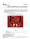
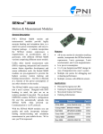
Here is an example of a passing output from the self-test initiated from the python script.
If the self-test fails, the sensor which failed shall be displayed on the python script window if the self-test
command is initiated from the python script.
14 Calibration Data and Storage
Calibration data contains information describing the inherent biases and temperature dependent behavior of
the MPU gyro, accelerometer, and compass. This data is used during MPL execution to improve the
accuracy of the results returned by the MPL. Calibration data may change slowly over time, temperature, and
environment so Invensense provides several in-use sensor calibration algorithms which will constantly
calibrate the sensors throughout its lifetime. Details are described in the Features Guide. It is recommended
that the MPU sensor accel and gyro be calibrated at the factory line and if using the MPL library to turn on
the in-use algorithms.
14.1 Factory Line calibration
The accel and gyro biases returned by the self-test function can be used for factory calibration and can be
saved by the HAL and used to calibrate the performance of the sensors. The biases can either be pushed to
the HW Offset registers or into the MPL library.
The MD6.0 by default pushed the biases into the MPL library and lets the fusion engine apply the bias data.
However customers can use the Hardware Offset Register by defining
USE_CAL_HW_REGISTERS
CONFIDENTIAL & PROPRIETARY
12 of 14
PRELIMINARY
Document Number: AN-EMAPPS-0.0.6
Motion Driver 6.0 – User Guide
Revision: 1.0
Release Date: 06/27/2014
in the main.c. The difference is that if using the HW offset registers the MEMS data will automatically be
adjusted before it is pushed into the sensor data registers. To understand the HW Offset Registers better
please see the app note ‘MPU HW Offset Registers’.
It is important that when you are doing factory line calibration, the device needs to be in a stable and
vibration free environment with the physical Accel Z+ facing up or down, this will be the face of the MPU IC
needs to be pointing up or down.
14.2 Saving and Loading Calibration Data
Calibration data is not generated, loaded, or stored automatically by the MPL. After biases are calculated
and applied, it will be lost once the device is powered off. Therefore InvenSense provides API examples on
how to save and load the calibration data from a memory location. Please look into functions
inv_error_t inv_save_mpl_states(unsigned char *data, size_t sz)
inv_error_t inv_load_mpl_states(const unsigned char *data, size_t length)
Customers can use these functions as an example of how to save into their devices memory. The calibration
should be saved after factory calibration and before power off. On power on it will need to be loaded back in.
15 Integrating the MPL Library
The MPL library is a precompiled library containing the sensor fusion engine. When porting MD6.0 the library
needs to be compatible with integrators system. The MD6.0 comes with 2 libraries.
TI MSP430 - compiled using Code Composer. Should be compatible with all MSP430 product line
ARM – compiled using the GNU non-eabi-arm 4.7.2 compiler. Generic library is compatible with all
ARM Cortex M0, M3, and M4’s. There is also a specific M3 and M4 compiled version for better
optimizations.
After the library is linked the code will need to enabled the library and it’s features. The library initialization
can be found in the main function before the main loop. The features are described in the Feature Guide.
Here are the associated APIs
inv_error_t inv_init_mpl(void)
inv_error_t inv_enable_quaternion(void) //enable 6-axis
inv_error_t inv_enable_9x_sensor_fusion(void) //enable 9-axis fusion
inv_error_t inv_enable_fast_nomot(void) //gyro in-use calibration
inv_error_t inv_enable_gyro_tc(void) //gyro temperature compensation
inv_error_t inv_enable_vector_compass_cal(void) //compass calibration
inv_error_t inv_enable_magnetic_disturbance(void) //magnetic disturbance
inv_error_t inv_enable_eMPL_outputs(void)
inv_error_t inv_start_mpl(void)
CONFIDENTIAL & PROPRIETARY
13 of 14
PRELIMINARY
Document Number: AN-EMAPPS-0.0.6
Motion Driver 6.0 – User Guide
Revision: 1.0
Release Date: 06/27/2014
16 Low Power Accel Mode and Motion Interrupt Mode for MPU6500/MPU9250
LPA mode and motion interrupt mode are similar and can be enabled with the device only needs accel data.
This feature is not supported in the MPU6050/MPU9150.
This feature requires that the DMP, FIFO, and gyro be disabled. It will then sleep cycle the accel waking it up
only at the specified rate the user requested. The different LPA rates are from 1.25Hz to 640hz. The lower
the rate the lower power it will consume. With the lowest rate the total power will be around 10uA.
Customers can also put the device into Motion Interrupt Mode. In this mode the device will be in LPA mode
and if the accel data exceeds a certain threshold it will generate an interrupt. This is particularly useful if
there is no motion and customers want to sleep the device until a movement is detected.
The associated APIs are –
int mpu_lp_accel_mode(unsigned short rate)
int mpu_lp_motion_interrupt(unsigned short thresh, unsigned char time,
unsigned short lpa_freq)
17 Compiler Specific Setting
To compile for the different parts (MPU6050, MPU9150, MPU6500, and MPU9250), you will need to set the
compiler flag
The default symbols needed are
MPL_LOG_NDEBUG=1
MPU9150 or MPU6050 or MPU6500 or MPU9250
EMPL
USE_DMP
EMPL_TARGET_MSP430 or its equivalent
Once the part is set the compiler will compile for that specific part and its features.
CONFIDENTIAL & PROPRIETARY
14 of 14
PRELIMINARY