1
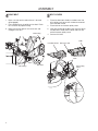
Operator and Parts Manual
Collection System
M-ZT 52 /966793002
M-ZT 61 /966793003
CONGRATULATIONS on the purchase of a new
collection system. It has been designed, engineered
and manufactured to give you the best possible
dependability and performance.
Should you experience any problem you cannot easily
remedy, please contact the nearest authorized service
center/ department. They have competent, welltrained technicians and the proper tools for service
and repairs.
Please read and retain this manual. The instructions
will enable you to assemble and maintain the
collection system properly. Always observe the
SAFETY RULES.
KNOW YOUR BLOWER SYSTEM
READ THIS OPERATION MANUAL AND SAFETY
RULES BEFORE ASSEMBLING OR OPERATING THE
BLOWER SYSTEM. Compare the illustrations with the
carton contents and become familiar with the parts
before starting the assembly. Study the operating
instructions and safety precautions thoroughly to
insure proper functioning of the Grass Catcher and to
prevent injuries. Save this manual for future reference.
CAUTION
CAUTION
BEFORE ASSEMBLING GRASS
CATCHER TO MOWER:
• Set parking brake.
• Place motion control levers in
NEUTRAL position.
• Turn ignition key OFF and remove
key.
• Make sure the blades and all moving
parts have completely stopped.
The operation of any mower can result
in foreign objects thrown into the eyes,
which can result in severe eye damage.
ALWAYS wear safety glasses or eye
shields before starting the mower and
while mowing. Standard safety glasses
are recommended or a wide vision safety
mask for over spectacles.
CAUTION
CAUTION
•
•
•
•
•
DO NOT operate mower with grass
catcher partially installed.
Disengage blades and stop engine
before leaving mower seat to empty
containers, unclogging chutes, etc.
Close cover before starting.
Disengage mower blades when
crossing driveways or gravel
surfaces and other areas where
thrown objects could be a hazard.
DO NOT attempt to vacuum cans
or other potentially hazardous
projectiles.
Do not leave grass in bagger containers.
Empty containers after each use and
before storing. Failure to do so may
result in spontaneous combustion which
could develop into a fire.
CAUTION
Grass catcher components are subject
to wear, damage and deterioration,
which could expose moving parts or
allow objects to be thrown. Frequently
check components and replace with
manufacturer’s recommended parts,
when necessary.
©2013 HTC. All Rights Reserved.
Swainsboro, GA. Printed in U.S.A.
CONTENTS
SAFETY RULES..........................................................4
ASSEMBLY.................................................................5
OPERATION.............................................................. 11
BLOWER ASSEMBLY.......................................12
CHUTES............................................................14
BAGGER...........................................................16
MOUNT, GUARD, BELT....................................18
TOOLS REQUIRED
CONTAINER CONTENTS
/16" Wrench or ratchet and socket
/16" Wrench or ratchet and socket
½" Wrench or ratchet and socket
¾" Wrench or ratchet and socket
7
/8" Socket
Torque Wrench
Phillips Head Screwdriver
Hacksaw
Pliers
Drill and 3/8" drill bit
•
•
•
7
9
NOTE: When the terms RH (right hand) or
LH (left hand) are used, it refers to when the
operator is seated on the mower.
Blower/Bagger Assembly • Drive Pulley
Belt Shield
• Belt
Mounting Brackets
• Bag of Hardware
SAFETY RULES
SAFE OPERATION PRACTICES FOR RIDE-ON MOWERS
GENERAL OPERATION
•
•
•
•
•
•
•
•
•
•
•
•
•
•
Read, understand and follow all instructions in the
manual and on the machine before starting.
Only allow responsible adults, who are familiar
with the instructions, to operate the machine.
Clear the area of objects such as rocks, stones,
toys, wire etc., which could be picked up and
thrown by the blades.
Be sure the area is clear of all people and pets
before mowing. Stop the machine if anyone enters
the area.
Never carry passengers or children even with
blades off.
Do not mow in reverse unless absolutely
necessary. Always look down and behind before
and while backing.
Do not operate the mower without either the entire
grass catcher or the guard in place.
Slow down before turning.
Stop engine before removing grass catcher or
unclogging chute.
Mow only in daylight or good artificial light.
Do not operate the machine while under the
influence of alcohol or drugs.
If the collection system has front weights
included, DO NOT operate mower with the grass
catcher unless the front weights are installed.
Keep machine free of grass, leaves or other
debris buildup which can touch hot exhaust/
engine parts and burn. Do not allow the mower
deck to plow leaves or other debris which can
cause buildup to occur.
Allow machine to cool before storage.
SLOPE OPERATION
Slopes are a major factor related to loss-of-control and
tip-over accidents, which can result in severe injury or
death. All slopes require extra caution. If you cannot
back up the slope or if you feel uneasy on it, do not
mow it.
DO
• Use extra care with grass catchers or other
attachments. These can change the stability of
the machine.
• Mow up and down slopes (10° Max.), not across.
• Remove obstacles such as rocks, tree limbs, etc.
4
•
Watch for holes, ruts, or bumps. Uneven terrain
could overturn the machine. Tall grass can hide
obstacles.
• Use slow speed. Choose a low speed so that you
will not have to stop while on the slope.
• Keep all movement on the slopes slow and
gradual. Do not make sudden changes in speed
or direction.
• Avoid starting or stopping on a slope. If tires
lose traction, disengage the blades and proceed
slowly straight down the slope.
DO NOT
• Do not turn on slopes unless necessary, and then,
turn slowly and gradually downhill, if possible.
• Do not mow near drop-off, ditches, or
embankments. The mower could suddenly turn
over if a wheel is over the edge of a cliff or ditch,
or if an edge caves in.
• Do not mow on wet grass. Reduced traction
could cause sliding.
• Do not try to stabilize the machine by putting your
foot on the ground.
SERVICE
•
•
•
•
The operation of any mower can result in foreign
objects thrown into the eyes, which can result in
severe eye damage. Always wear safety glasses
or eye shields while operating the mower or
performing any adjustments or repairs. Wide
vision safety mask over spectacles or standard
safety glasses are recommended.
Keep nuts and bolts, especially blade attachment
bolts, tight and keep equipment in good
condition.
Never tamper with safety devices. Check there
proper operation regularly.
Grass catcher components are subject to wear,
damage, and deterioration, which could expose
moving parts or allow objects to be thrown.
Frequently check components and replace
with manufacturer’s recommended parts, when
necessary.
ASSEMBLY
1
2
DRIVE PULLEY
1. Remove the discharge chute from the deck
by removing the side hardware from the chute
bracket. Retain the hardware for reuse if the
collection system is removed.
2. Lower deck to the lowest cutting position.
3. Remove the right hand (discharge side) belt cover
from the deck.
TRIMMING BLOWER
1. Place blower assembly on secure table or stable
surface.
2. Remove the bolts securing the rear mount
bracket.
3. Using the hacksaw, trim the blower housing along
the recessed grooves.
4. Reinstall the rear mount bracket with previously
removed bolts.
Belt Cover
Discharge
Chute
Hardware
4. Relieve the tension from the deck belt and remove
the belt from the center deck pulley.
(See Operator Manual if necessary)
5. Remove the nut securing the right hand deck
pulley to the spindle.
6. Install drive pulley included in collection system
kit on top of the current deck pulley.
7. Reinstall the nut on the spindle and torque to 5575 ft/lbs.
8. Reinstall the deck belt.
Mount Bracket
Rear
Trim Line
3
MOUNTING BLOWER ASSEMBLY
1. Position blower over the discharge tabs on the
deck and set blower onto the deck.
2. Install the front mount bracket to the deck with the
pin and hairpin cotter supplied with the kit.
Drive Pulley
Outer Pulley Cover
Pin
5
ASSEMBLY
4
5
DRIVE BELT
1. Make sure the tension release lever is forward
(disengaged).
2. Place the belt over the pulley on the deck. Refer
to illustration for proper routing.
3. Move the tension release arm to the rear and
engage in the latch.
Outer Pulley
BELT COVERS
1. Place the deck belt shield on the deck over the
drive pulley and secure with hardware removed
from steel belt shield.
2. Place retainer on the outer pulley cover.
3. Align the tab end of the belt cover into the slot on
the deck belt shield and the other end over the
end of the outer pulley cover.
4. Secure with knob.
Deck Belt Shield
Belt Cover Tab
Knob
Middle Chute
Latch
Idler Pulleys
Belt Twist
Outer Pulley
Cover
Retainer
6
ASSEMBLY
6
BAGGER MOUNT
1. Using 1¾" round head shoulder bolts and nuts,
attach the mount hitch to the mount tube as
illustrated. Make sure the elbowed arm of the tube
is on the right side, with the mount hitch installed
to the front.
2. Attach the support bracket to the tube assembly
with two 1¾" round head shoulder bolts and nuts.
3. With a 1" hex bolt and nut, secure the lower mount
hitch to the frame.
FRONT
Spacer Plate
4. Install the mount straps (bends are to the inside)
on the outside of the mount tube using 2" hex
bolts and nuts. The front side of the mount straps
are secured to the fuel tank brackets with 1" round
head shoulder bolts and nuts.
5. To prevent contact of the left hand strap with
the EFM (Electronic Fuel Management) box on
the engine, place the foam strip on the inside of
the strap, next to the box. (Illustration location is
approximate.)
6. It may necessary to drill holes into the rear
guard to accept the hardware for the support
bracket and spacer plate. Using the bracket as a
template, drill 5/16" holes.
7. Slip the spacer plate between the support bracket
and the rear guard and attach both to the rear
guard with ¾" hex bolts and nuts as illustrated.
8. Tighten all hardware.
Foam Strip
Mount Straps
Support Bracket
Mount Tube
Lower Mount Hitch
Support Bracket and
Spacer Plate
7
ASSEMBLY
7
8
CHUTE SUPPORT
1. Position upper chute support against bagger inlet,
flush at outer edges. See Illustration.
2. Using support as a template, drill two 3/8 holes into
bagger hood.
COVER ASSEMBLY
NOTE: For ease of assembly, you may wish
assistance from another person for mounting
the cover assembly to mower.
1. Position cover assembly on ground behind
mower.
2. Lift and rotate cover to align the cover brackets
with support assembly tubes.
3. Slide the cover down over the support tubes until
secure.
Upper Chute Support
Cover Assembly
3. Secure upper chute support to hood with hex
bolts, washers and nyloc nuts.
Flex Trim
9
MIDDLE CHUTE
1. Place middle chute over the top end of the blower
assembly, lining up the blower latch and the
acorn nut on the middle chute.
2. Stretch bungee latch up onto acorn nut to secure.
Middle Chute
Chute Latch
8
ASSEMBLY
10
11
1. Slide upper chute onto middle chute, lining up the
middle chute latch and the acorn nut on the upper
chute.
2. Stretch bungee latch up onto acorn nut to secure.
Push upper chute through the gasketed opening in
the cover assembly.
UPPER CHUTE ASSEMBLY
CHUTE / HOOD INSTALLATION
Cover Inlet
Upper Chute
9
ASSEMBLY
12
WEIGHT ASSEMBLY
1. Remove the foot plate knob and foot plate. Set
aside for later reuse.
2. Remove and reserve the three rubber grommets
from the foot rest.
3. Remove the foot rest for replacement. Retain
hardware for reuse.
6. Fasten the three weight plates to the weight
brackets.
Foot Plate
Foot Rest
4. Install the three rubber grommets to the new foot
rest and fasten the assembly to the frame with the
hardware from the old foot rest.
5. Reinstall the foot plate and secure with the knob.
7. Secure the weight plate assembly to the front
frame of the mower between the caster wheels.
Replacement Foot Rest
Weight Plate
Assembly
10
OPERATION
TIPS FOR IMPROVED BAGGING
•
•
•
•
•
Follow the mower operation instructions in you
mower operator manual.
When operating the grass catcher on a lawn
where grass and leaf bagging equipment has
not been used, thatch and debris that has
accumulated for long periods of time is picked
up. The amount collected and the total time of
operation may be greater than experienced with
regular use of the grass catcher.
Always run throttle at full speed when bagging.
Select a speed low enough to give good mower
cutting performance, good quality cut and good
bagging performance.
NOTE: It may be necessary to overlap width of
cut to suit conditions.
If grass is extremely tall, it should be mowed
twice. The first time relatively high, the second
time to desired height.
• Use left hand side of mower for trimming.
• Plastic trash bags (3.0 mil, 30 gallon) can be
inserted inside grass catcher containers for ease
of debris disposal. To remove the plastic trash
bags when full:
a. Disengage blades, shift into neutral, engage
the parking brake and stop the engine.
b. Unlatch and raise cover.
c. Remove one container at a time by grasping
container handles and pulling toward the rear,
off of the tube rails.
d. With the container resting on the ground, close
and secure the top of the plastic lawn bag.
e. Tip the container on its side and slide the filled
bag from the container.
f. Install a new plastic lawn bag with the edges
of the bag draped over upper lip of the
Container.
g. Repeat for other containers.
h. Reinstall containers making sure center
containers overlap at center supports.
i. Close cover and secure latches over center
support tubes.
• Avoid cutting wet grass or in the morning while the
dew is still heavy. Grass clippings collected under
these conditions tend to be sticky and adhere to
the walls of the flow path causing clogging.
•
If the grass catcher fails to pick up cut grass
or leaves, it is an indication that clogging has
occurred in the system or that the grass catcher
containers are full.
a.Disengage blades, place motion control levers
in neutral position.
- Unlatch and raise cover.
- Slide out containers and dispose of
clippings.
- Replace containers, close cover, and latch.
b.Unlatch chutes and check for clogging.
- Remove all debris in chute.
- Reassemble and latch chutes.
GENERAL RECOMMENDATIONS
Always observe safety rules when performing any
maintenance. Before each use check for loose
fasteners. Clean unit thoroughly after each use.
BLADE CARE
For best results mower blades must be kept sharp.
Replace bent or damaged blades.
See BLADE CARE instructions in the mower operator
manual.
STORAGE
When grass catcher is to be stored for a period of
time, clean it thoroughly, remove all dirt, grass, leaves,
etc. Store in a clean, dry place.
11
REPAIR PARTS
BLOWER ASSEMBLY
46
24
65
34
18
51
16
12
19
53
53 32
25
63 27
13 43
26
4
13
8
58
50
48
37
14
23
63
40
52
45
41
21
40
63
6
50
10
32
50
66
58
57
5
38
33
7
2
22
58
17
60
49
15
48
31
59
42
65
20
35
29
64
47
12
59
60
1
9
11
3
54
56 55
44
30
64
58
61
62
56
28
REPAIR PARTS
ITEM PART NO.
QTY.
DESCRIPTION
ITEM PART NO.
QTY.
QTY.
DESCRIPTION
1.. 539 130344���� 1���� HOUSING w/DECALS
33.. 539 130296���� 2���� BEARING
2.. 539 130293���� 1���� COVER, BELT
34.. 522 909602���� 1���� BRACKET, MOUNT
3.. 574 411501���� 1���� COVER, BELT
35.. 522 909502���� 1���� BRACKET, RETENTION
4.. 539 130292���� 1���� IMPELLER
36.. 525 618302���� 1���� SAND LINER, TOP
5.. 539 130295���� 1���� HUB
37.. 522 909702���� 1���� SAND LINER, BOTTOM
6.. 539 113683���� 1���� PULLEY, V-IDLER
38.. 539 990645���� 1���� RHSNB 3/8-16 x 1
7.. 539 130324���� 1���� PULLEY
39.. 539 990316���� 6���� RHSNB 5/16-18 x ¾
8.. 579 150802���� 1���� PULLEY, IDLER
40.. 539 990208���� 6���� RHSNB 5/16-18 x 1
9.. 579 137402���� 1���� MOUNT, UPPER BLK
41.. 539 976949���� 1���� HCS 3/8-16 x 1¾
10.. 579 137502���� 1���� MOUNT, LOWER BLK
42.. 539 101721���� 4���� HCS 5/16-18 x 2¾
11.. 579 137302���� 1���� ARM, IDLER
43.. 539 990643���� 1���� HCS ¼-20 x 7/8
12.. 539 130338���� 1���� ARM, TENSION
44.. 539 990209���� 1���� HCS 5/16-18 x 1
13.. 539 130301���� 2���� BUSHING
45.. 539 990655���� 1���� HCS 3/8-16 x 1½
14.. 539 132124���� 1���� PLATE, BACKING
46.. 539 130315���� 6���� HCS 5/16-18 x ½
15.. 539 130341���� 1���� PLATE, OUTER
47.. 539 108461���� 3���� BOLT ¼-20 x ½ HWST
16.. 539 104411���� 1���� KNOB w/ STUD
48.. 539 110321���� 2���� BOLT 3/8-24 x 1¼ HEX GR 8
17.. 539 130323���� 1���� SPACER
49.. 539 990302���� 8���� SCREW ¼-20 x 3/8 THD FRM
18.. 522 909801���� 1���� PIN, RETENTION
50.. 539 976952���� 1���� SCREW #10-24 x 5/8 MACH
19.. 539 108088���� 1���� LATCH, HOOD
51.. 539 130313���� 6���� NUT 5/16-18 TEE
20.. 539 115667���� 1���� KEY 3/16 x ½
52.. 539 130314���� 9���� NUT ¼-20 TEE
21.. 539 125229���� 1���� KEY 1½
53.. 539 108089���� 1���� WELDNUT, PLATED
22.. 539 104763���� 1���� RETAINER, U TYPE
54.. 539 108120���� 1���� NUT ¼-20 HEX THIN NYLOC
23.. 539 130316���� 1���� SHAFT, IMPELLER
55.. 539 108735���� 1���� NUT ¼-20 HEX FLANGE LK
24.. 539 976988���� 1���� HAIRPIN COTTER
56.. 539 200282���� 3���� NUT 3/8-16 HEX JAM NYLOC
25.. 539 130349���� 1���� DECAL, BELT ROUTING
57.. 539 112899�� 10���� NUT 5/16-18 HEX FLG NYLOC
26.. 539 105785���� 1���� DECAL, WARNING
58.. 539 990717���� 9���� NUT 5/16-18 HEX NYLOC
27.. 539 106741���� 1���� DECAL, SEVERING
59.. 539 990118���� 2���� WASHER 3/8 SLW
28.. 539 101977���� 1���� SPRING, TRACTION
60.. 532 140296���� 2���� WASHER, HARDENED
29.. 522 909402���� 1���� TUBE, RUB
61.. 539 108084���� 1���� WASHER 3/16 x ¾ x 16 GA
30.. 579 137602���� 1���� KEEPER, BELT REAR BLK
62.. 539 109552���� 1���� WASHER 3/16 SLW
31.. 539 131085���� 1���� KEEPER, BELT OUTER BLK
63.. 539 990122���� 3���� WASHER 3/8 SAE FLT
32.. 579 137702���� 1���� KEEPER
64.. 539 990055���� 4���� WASHER ¼ FLAT SAE
65.. 539 990188�� 10���� WASHER 5/16 SAE FLAT
NOTE: ALL FASTENERS ARE GRADE 5 UNLESS OTHERWISE SPECIFIED.
13
REPAIR PARTS
CHUTES
3
7
2
1
12
10
11
4
9
11
5
5
9
11
6
8
14
8
REPAIR PARTS
ITEM PART NO.
QTY.
DESCRIPTION
ITEM PART NO.
QTY.
DESCRIPTION
1.. 539 108141���� 1���� CHUTE, UPPER
7.. 539 976952���� 1���� SCREW #10-24 x 5/8
2.. 539 130294���� 1���� CHUTE, MIDDLE
8.. 539 108083���� 2���� SCREW #10-24 x 11/8
3.. 539 130933���� 1���� INDICATOR, BAG DUMP
9.. 539 108086���� 2���� NUT #10-24 ACORN
4.. 539 108088���� 1���� LATCH, HOOD
10.. 539 108089���� 1���� WELDNUT, PLATED
5.. 539 108085���� 2���� SPACER, SPLIT
11.. 539 108084���� 3���� WASHER 3/16 x ¾ x 16 GA
6.. 539 108081���� 1���� SCREW #10-14 x ½
12.. 539 109552���� 2���� WASHER 3/16 LOCK
NOTE: ALL FASTENERS ARE GRADE 5 UNLESS OTHERWISE SPECIFIED.
15
REPAIR PARTS
BAGGER
1
16
3
8
9
14
16
5
11
15
13
17
10
7
6
4
12
2
16
15
REPAIR PARTS
ITEM PART NO.
QTY.
DESCRIPTION
ITEM PART NO.
QTY.
DESCRIPTION
1.. 532 195373���� 1���� COVER
10.. 539 110281���� 1���� SUPPORT, CHUTE
2.. 532 400226���� 3���� CONTAINER, SOFT BAG
11.. 539 112294���� 1���� FLEX TRIM
3.. 532 130895���� 2���� HANDLE, BAGGER COVER
12.. 539 108096���� 2���� HAIR PIN
4.. 532 176990���� 1���� FRAME, BAGGER
13.. 539 990627���� 2���� HCS 5/16-18 x 1¼
5.. 532 192709���� 1���� SCREEN, COVER
14.. 539 976952���� 6���� SCREW #10-24 x 5/8
6.. 532 174083���� 2���� PLUG, SPACER
15.. 539 112899���� 2���� NUT 5/16-18 HEX FLG NYLOC
7.. 532 192786���� 2���� PIN, HINGE
16.. 539 976977���� 6���� NUT #10-24 CROWNLOCK
8.. 532 192550���� 1���� SEAL, COVER
17.. 539 990188���� 4���� WASHER 5/16 SAE
9.. 532 192603���� 1���� GASKET, COVER
NOTE: ALL FASTENERS ARE GRADE 5 UNLESS OTHERWISE SPECIFIED.
17
REPAIR PARTS
MOUNT, GUARD, BELT
10
2
1
23
4
18
27
22
9
3
12
14
21
22
25
19
25
13
8
11
7
24
17
6
16
15
25
20
5
26
17
18
28
REPAIR PARTS
ITEM PART NO.
QTY.
DESCRIPTION
1.. 539 130307���� 1���� SHIELD, BELT, 52"
539 130308���1���� SHIELD, BELT, 61"
2.. 539 130320���� 1���� PULLEY, 52"
539 130321���1���� PULLEY, 61"
3.. 539 130347���� 1���� BELT 52"
ITEM PART NO.
QTY.
DESCRIPTION
15.. 576 221502���� 1���� SPACER
16.. 539 990645���� 2���� RHSNB 3/8-16 x 1
17.. 539 990861���� 4���� RHSNB 5/16-18 x 1¾
18.. 539 101341���� 4���� HCS 3/8-16 x 3
19.. 539 102334���� 4���� HCS 3/8-16 x 4½
539 130348���1���� BELT 61"
20.. 539 990646���� 1���� HCS ½-13 x 1
4.. 584 812002���� 1���� FOOT REST
21.. 539 976937 ��� 2 ��� HCS 5/16-18 x 2
5.. 539 132192���� 1���� MOUNT, HITCH
22.. 539 990122 ��� 8 ��� WASHER 3/8 SAE FLT
6.. 576 221402���� 1���� BRACKET, SUPPORT
23.. 539 990118 ��� 4 ��� WASHER 3/8 LK
7.. 539 132198 ��� 1 ��� STRAP, RT BLK
24.. 525 464701 ��� 3 ��� HHFS 5/16-18 x ¾
8.. 575 953302���� 1 ��� STRAP, LT BLK
25.. 539 112899���� 9���� NUT 5/16-18 HEX FLG NYLOC
9.. 539 113232���� 6���� PLATE, WEIGHT
26.. 539 101331���� 1���� NUT ½-13 HEX NYLOC
10.. 522 989002���� 2���� BRACKET, WEIGHT
27.. 521 966501���� 8���� NUT 3/8-16 HEX FLG NYLOC
11.. 539 131091 ��� 1 ��� TUBE, MOUNT
28.. 539 976979��� 2���� NUT 3/8-16 HEX NYLOC
12.. 539 105743���� 1���� DECAL, NO STEP
NOT SHOWN
539 110290���1���� BLOCK, FOAM
13.. 532 428676���� 1���� DECAL, CROWN
14.. 539 121322���� 2���� ABRASIVE PAD
NOTE: ALL FASTENERS ARE GRADE 5 UNLESS OTHERWISE SPECIFIED.
19
115 584027 Rev A
2013-02-15