1
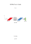
SENtral M&M
Motion & Measurement Modules
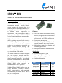
General Description
PNI’s SENtral M&M motion and
measurement modules provide highly
accurate heading and orientation data, in a
small, low-power-consumption, and easy-tointegrate package. A module incorporates
the SENtral motion coprocessor, a
magnetometer, an accelerometer, and a
gyroscope, with different SENtral M&M
versions comprising different sensor models.
Unlike other inertial measurement units
(IMUs) requiring unexpected and extensive
sensor fusion algorithm development and
sensor calibration work, the Sentral M&M
modules are pre-engineered to provide the
highest accuracy motion tracking and
heading measurement. And this is obtained
at a fraction of the power consumption of
any other solution on the market.
The SENtral M&M comes ready to integrate
into a user’s system. Designed with SMT
bonding in mind, the pins are on an
industry-standard 3 mm pitch. The on-board
EEPROM contains SENtral’s configuration
file and this automatically uploads into
SENtral RAM when powered up.
Communication is via I2C protocol.
With the SENtral M&M modules you can
quickly and easily incorporate industryleading motion-tracking and orientation
measurement in your mobile device. We’re
sure you’ll be impressed.
Features
All-in-one motion & orientation tracking
module, incorporates the SENtral motion
coprocessor, 3-axis gyroscope, 3-axis
accelerometer, and 3-axis magnetometer.
Low power consumption.
11x11 mm footprint and SMT design for
ease of integration into a user’s system
Multiple test points for debugging and
evaluating performance.
Multiple versions with different sensors.
Applications
Personal Navigation & LBS
Gaming & Augmented Reality
Movement Science & Fitness
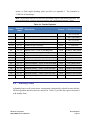
Ordering Information
Item
Sensors
Part #
White M&M
none (Sentral only)
13734
Orange M&M
BMI055+AK8963
13771
Red M&M
MPU6500+AK8963
13763
Green M&M
LSM330+AK8963
13736
Yellow M&M
LSM9SD0
13738
Blue M&M
LSM330+RM3100
13759
Table of Contents
1
PRODUCT OVERVIEW ............................................................................................... 3
1.1
SENTRAL FEATURES AND BENEFITS ........................................................ 3
1.2
SENTRAL M&M SYSTEM OVERVIEW .......................................................... 4
1
2
SENTRAL SPECIFICATIONS .................................................................................... 6
2.1
PERFORMANCE CHARACTERISTICS ......................................................... 6
2.2
ELECTRICAL CHARACTERISTICS ............................................................... 6
3
INTERFACE ................................................................................................................. 8
2
3.1
I C TIMING ...................................................................................................... 9
2
3.2
I C HOST INTERFACE (HOST BUS) ........................................................... 10
2
3.2.1 I C Transfer formats ......................................................................... 11
2
3.3
I C SENSOR INTERFACE (SENSOR BUS) ................................................. 11
3.4
HOST INTERRUPT/GPIO LINES ................................................................. 12
4
OPERATION .............................................................................................................. 13
4.1
POWER-UP ................................................................................................... 14
4.2
INITIAL REGISTER SET-UP ......................................................................... 14
4.3
RUNNING IN NORMAL OPERATION .......................................................... 16
4.3.1 Error .................................................................................................. 18
4.3.2 Read Results .................................................................................... 18
4.4
STANDBY STATE ......................................................................................... 19
4.5
PASS-THROUGH STATE ............................................................................. 20
4.6
TROUBLESHOOTING .................................................................................. 22
4.6.1 Hardware-Related Error Conditions ................................................. 22
4.6.2 Software-Related Error Conditions ................................................... 23
5
PACKAGE INFORMATION ....................................................................................... 24
6
ASSEMBLY GUIDELINES ......................................................................................... 26
APPENDIX I – CONVERTING QUATERNIONS .................................................................... 28
APPENDIX II – MEASURING CURRENT CONSUMPTION .................................................. 30
PNI Sensor Corporation
SENtral M&M Technical Datasheet
Doc #1020129 rD
Page 1
List of Figures
Figure 1-1:
Figure 3-1:
Figure 3-2:
Figure 3-3:
Figure 3-4:
Figure 4-1:
Figure 4-2:
Figure 4-3:
Figure 5-1:
Figure 5-2:
Figure 5-3:
Figure 6-1:
Figure 6-2:
Figure 6-3:
Figure A-1:
SENtral M&M Module Reference Schematic ......................................................... 4
2
I C Timing Diagram ................................................................................................ 9
2
I C Slave Write Example ...................................................................................... 11
2
I C Slave Read Example, with Repeated START................................................ 11
2
I C Slave read register from current address ....................................................... 11
SENtral Initialization Sequence ............................................................................ 13
SENtral Operational States .................................................................................. 13
SENtral Normal Operation Flow ........................................................................... 18
SENtral Orange, Red, Green, & Yellow M&M Mechanical Drawing .................... 24
SENtral White M&M Mechanical Drawing............................................................ 24
SENtral Blue M&M Mechanical Drawing.............................................................. 25
SENtral Orange, Red, Green, & Yellow M&M Solder Pad Layout ....................... 26
SENtral White M&M Solder Pad Layout .............................................................. 26
SENtral Blue M&M Solder Pad Layout ................................................................ 27
SENtral Blue M&M Zero-Ohm Resistor Location ................................................ 30
List of Tables
Table 2-1:
Table 2-2:
Table 2-3:
Table 3-1:
Table 3-2:
Table 4-1:
Table 4-2:
Table 4-3:
Table 4-4:
Table 4-5:
Table 4-6:
Table 4-7:
Table 4-8:
Table 4-9:
Performance Characteristics ................................................................................... 6
Absolute Maximum Ratings .................................................................................... 6
Operating Conditions............................................................................................... 7
SENtral M&M Module Pin Assignments .................................................................. 8
2
I C Timing Parameters .......................................................................................... 10
Configuration File Upload from EEPROM Registers ............................................ 14
Registers for Initial Set-up ..................................................................................... 15
Normal Operation Registers .................................................................................. 17
Results Registers .................................................................................................. 19
Standby Registers ................................................................................................. 20
Pass-Through Registers........................................................................................ 21
Hardware-Related Error Indications ...................................................................... 22
Software-Related Error Indications ....................................................................... 23
ErrorRegister Indications ....................................................................................... 23
PNI Sensor Corporation
SENtral M&M Technical Datasheet
Doc #1020129 rD
Page 2
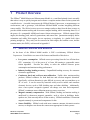
1
Product Overview
The SENtral M&M Motion and Measurement Module is a castellated printed-circuit assembly
that makes it easy to quickly integrate and evaluate a complete motion sensor fusion system into
a mobile device. A module incorporates the SENtral Motion Coprocessor, a magnetometer, an
accelerometer, and a gyroscope, with different SENtral M&M versions integrating different
sensor models. The SENtral motion coprocessor manages and uses data from the three sensors to
provide reliable motion tracking and an accurate compass heading, while consuming about 1% of
the power of a comparable ARM-based sensor fusion microprocessor. SENtral outputs Euler
angles (aka heading, pitch, and roll), quaternions, and sensor data. Quaternions uniquely define
orientation and, unlike Euler angles, do not experience a singularity (i.e. gimbal lock) when
pointing straight up. They easily can be converted to Euler angles, the rotation vector, and the
rotation matrix (aka DCM), as discussed in Appendix I.
1.1 SENtral Features and Benefits
At the heart of the SENtral M&M module is PNI’s revolutionary SENtral Motion
Coprocessor. Listed below are some of the features and benefits of this device.
Low power consumption. Offloads sensor processing from the less efficient host
CPU, consuming <1% of the power of a Cortex M0 running a comparable sensor
fusion algorithm. Provides the ability to tailor the tradeoff between power
consumption and motion-tracking performance.
Industry-leading heading accuracy. Unparalleled heading accuracy for consumer
electronics applications.
Continuous hard and soft-iron auto-calibration. Unlike other motion-tracking
products, SENtral calibrates for both hard-iron and soft-iron magnetic distortion.
Specifically, soft-iron distortion is quite difficult to correct, and can contribute up to
90° of error. It can be caused by materials widely used in mobile and consumer
electronic devices, such as EMI shielding tape and other shielding. Additionally,
since a host system’s magnetic signature can change over time and temperature,
SENtral’s continuous auto-calibration ensures accuracy over time.
Magnetic anomaly compensation. With SENtral, heading and motion tracking is
unaffected by short-term magnetic anomalies, such as rebar in buildings, desks,
speakers etc., that can easily throw off the accuracy. SENtral establishes if a transient
magnetic anomaly is present and compensates for this.
Sensor flexibility. SENtral works with most common consumer electronics motion
sensors, so designers can choose the sensors most appropriate for their systems.
PNI Sensor Corporation
SENtral M&M Technical Datasheet
Doc #1020129 rD
Page 3
Small form-factor. 1.6x1.6x0.5 mm chip-scale package on 0.4 mm pitch. Uses little
PCB real estate, allowing for painless integration.
I2C interface. Uses industry-standard I2C protocol in a low-power implementation to
interface to the sensors and the host, so system integration is straightforward.
Standard, Fast, Fast Plus, and High Speed are supported on the host bus.
Outputs. SENtral natively outputs Euler angles (heading, pitch, and roll),
quaternions, rotational velocity, linear acceleration, and magnetic field.
Pass-Through allows for direct communication with devices on the I2C sensor bus.
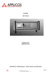
1.2 SENtral M&M System Overview
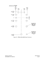
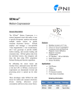
Figure 1-1 provides a reference schematic for SENtral M&M modules. While this diagram
applies for most versions so the SENtral M&M, the White and Blue M&M modules are
significantly different. Specific schematics for each module are available from PNI. How to
interface with the SENtral M&M is covered in more detail in Section 3.
Figure 1-1: SENtral M&M Module Reference Schematic
A few points on diagram:
The layout shows a discrete magnetometer, accelerometer, and gyroscope. SENtral
M&M modules generally incorporate a combo sensor that combines the gyroscope
and accelerometer into a single device or all three sensors into a single device.
PNI Sensor Corporation
SENtral M&M Technical Datasheet
Doc #1020129 rD
Page 4
SENtral acts as a slave on a host system I2C bus. This does not need to be a dedicated
bus, although it is shown this way in the schematic.
The SCLM and SDAM lines can be used to monitor SENtral’s I2C sensor bus, but
this is not necessary. These lines are optional and may be left unconnected.
If the host will poll SENtral, rather than running in an interrupt-driven manner, it is
not necessary to connect GPIO[6], the host interrupt line, to the host system.
GPIO[4] is intended for future use and currently serves no purpose. This can be left
unconnected.
PNI Sensor Corporation
SENtral M&M Technical Datasheet
Doc #1020129 rD
Page 5
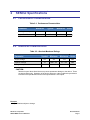
2
SENtral Specifications1
2.1 Performance Characteristics
Table 2-1: Performance Characteristics
Parameter
Minimum
Typical
Heading Accuracy
2
Output Data Rate
200
Maximum
Units
° rms
400
Hz
2.2 Electrical Characteristics
Table 2-2: Absolute Maximum Ratings
Parameter
Symbol
Minimum
Maximum
Units
Supply Voltage
VDD
-0.3
+3.6
VDC
Input Pin Voltage
VIN
GND – 0.3
VDD + 0.3
VDC
-50°
+150°
C
Storage Temperature
CAUTION:
Stresses beyond those listed above may cause permanent damage to the device. These
are stress ratings only. Operation of the device at these or other conditions beyond those
indicated in the operational sections of the specifications is not implied.
Footnote
1. Specifications subject to change.
PNI Sensor Corporation
SENtral M&M Technical Datasheet
Doc #1020129 rD
Page 6
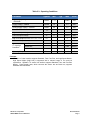
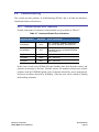
Table 2-3: Operating Conditions
Parameter
Symbol
Min
Digital Supply Voltage – Sensors &
EEPROM
DVDD
Supply Voltage – SENtral
Analog Supply Voltage – Sensors
Power-On Reset Threshold
Max
Units
1.71
AVDD
VDC
DVDD2
1.6
3.3
VDC
AVDD
2.4
3.6
VDC
VPOR
Typ
1.0
VDC
High Level Input Voltage
VIH
0.7*VDD
VDD
VDC
Low Level Input Voltage
VIL
0
0.3*VDD
VDC
High Level Output Current, VOH = VDD – 0.3V
IOH
-1
mA
Low Level Output Current, VOL = 0.3V
IOL
1
mA
Host Bus
3400
kbits/sec
Sensor Bus
1000
kbits/sec
Pass-Through
400
kbits/sec
+85
C
2
I C Interface
1
Data Rate
Operating Temperature
TOP
-40
+25
Footnote:
2
1. SENtral’s I C Host Interface supports Standard, Fast, Fast Plus, and High Speed Modes.
High Speed Mode (3400 kHz) is supported with a reduced range of V DD and bus
2
capacitance. SENtral’s I C sensor bus interface supports Standard, Fast, and Fast Plus
Modes. Pass-Through state, which connects the sensor bus and host bus, supports
Standard and Fast Modes.
PNI Sensor Corporation
SENtral M&M Technical Datasheet
Doc #1020129 rD
Page 7
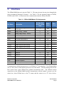
3
Interface
The SENtral M&M pin-out is given in Table 3-1. The same pin-outs also are given alongside the
device mechanical drawings in Section 5. See Table 2-3 for the operating ranges of DVDD,
DVDD2, and AVDD. A discussion of the communication interface follows the table.
Table 3-1: SENtral M&M Module Pin Assignments
Orange, Red,
Green, Yellow
Pin#
White
Pin #
Blue
Pin #
Pin Name
Description
DVDD
Digital Supply Voltage – Sensors &
EEPROM
1
NA
2
DVDD2
Supply Voltage – SENtral
2
D1
2
AVDD
Analog Supply Voltage – Sensors
7
NA
7
GND
Ground
8
D2
8
SCLS
I C host bus SCL clock line
2
3
B1
3
2
5
A1
5
2
9
A4
9
2
SDAS
I C host bus SDA data line
SDAM
I C sensor bus SDA data line
SCLM
I C sensor bus SCL clock line
10
B4
10
GPIO[0]
SENtral Accelerometer Interrupt
--
D4
--
GPIO[1]
SENtral Magnetometer Interrupt
--
C4
--
GPIO[2]
SENtral Gyroscope Interrupt
--
A3
--
GPIO[3]
Reserved
--
B3
--
GPIO[4]
Reserved
6
A2
6
GPIO[5]
Reserved
--
B2
--
GPIO[6]
Host Event Interrupt
4
C1
4
SA0
Slave Address Pin 0
--
C3
--
VCAP
Regulator Capacitor
--
D3
--
Reserved
Reserved (not connected)
--
C2
1, 12, 13
Communication with the host processor is via SENtral’s I2C host interface. The SENtral M&M
acts as a slave device while the host processor acts as the master. The host interrupt line lets the
host system know when SENtral has updated measurement data. The SENtral motion
coprocessor on the SENtral M&M module communicates with the module’s sensors over the
sensor bus, where SENtral acts as the I2C master and the sensors act as I2C slave devices.
PNI Sensor Corporation
SENtral M&M Technical Datasheet
Doc #1020129 rD
Page 8
Understanding how the sensor bus operates is not necessary when using the SENtral M&M
module, but it may be useful if operating in Pass-Through state.
SENtral’s I2C interfaces comply with NXP’s UM10204 specification and user manual, rev 04.
Standard, Fast, Fast Plus, and High Speed modes of the I2C protocol are supported by SENtral’s
I2C host interface. Below is a link to this document.
http://www.nxp.com/documents/user_manual/UM10204.pdf
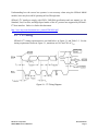
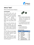
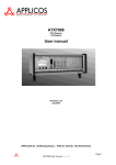
3.1 I2C Timing
SENtral’s I2C timing requirements are set forth below, in Figure 3-1 and Table 3-2. For the
timing requirements shown in Figure 3-1, transitions are 30% and 70% of VDD.
Figure 3-1: I2C Timing Diagram
PNI Sensor Corporation
SENtral M&M Technical Datasheet
Doc #1020129 rD
Page 9
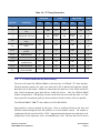
Table 3-2: I2C Timing Parameters
Standard
Fast
Fast Plus
Units
Symbol
Parameter
Min
Max
Min
Max
Min
Max
fSCL
SCL Clock
0
100
0
400
0
1000
kHz
tr
SDA & SCL Rise
Time
-
1000
20
300
120
ns
tf
SDA & SCL Fall Time
-
300
20*(VDD/
5.5V)
300
20*(VDD/
5.5V)
120
ns
tLOW
LOW period of SCL
Clock
4.7
-
1.3
-
0.5
-
s
tHIGH
HIGH period of SCL
Clock
4.0
-
0.6
-
0.26
-
s
tHD;STA
Hold time (repeated)
START
4.0
-
0.6
-
0.26
-
s
tHD;DAT
Data hold time
0
-
0
-
0
-
s
tSU:DAT
Data set-up time
250
-
100
-
50
-
ns
tSU;STA
Set-Up time for
repeated Start
4.7
-
0.6
-
0.26
-
s
tSU;STO
Stop set-up time
4.0
-
0.6
-
0.26
-
s
tBUF
Bus free time between
STOP & START
4.7
-
1.3
-
0.5
-
s
3.2 I2C Host Interface (Host Bus)
The host will control the SENtral M&M on the host bus via SENtral’s I2C host interface.
The host interface consists of 2 wires: the serial clock, SCLS, and the serial data line, SDAS.
Both lines are bi-directional. SENtral is connected to the host bus via the SDAS and SCLS
pins, which incorporate open drain drivers within the device. Note the SENtral M&M
module incorporates 4.7 kΩ pull-up resistors on the host bus clock and data lines, so if the
host system also incorporates pull-up resistors on these line the resistors will act in parallel.
The SENtral M&M’s 7-bit I2C slave address is 0x28 (0b0101000).
Data transfer is always initiated by the host. Data is transferred between the host and
SENtral serially through the data line (SDAS) in an 8-bit transfer format. The transfer is
synchronized by the serial clock line, SCLS. Supported transfer formats are single-byte read,
multiple-byte read, single-byte write, and multiple-byte write. The data line can be driven
PNI Sensor Corporation
SENtral M&M Technical Datasheet
Doc #1020129 rD
Page 10
either by the host or SENtral. Normally the serial clock line will be driven by the host,
although exceptions can exist when clock-stretching is implemented in Pass-Through State.
I2C Transfer formats
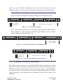
3.2.1
Figure 3-2 illustrates writing data to registers in single-byte or multiple-byte mode.
START
SLAVE ADDRESS
S
A6 A5 A4 A3 A2 A1 A0
RW ACK
0
0
REGISTER ADDRESS (N)
ACK
DATA TO REGISTER (N)
A7 A6 A5 A4 A3 A2 A1 A0
0
A7 A6 A5 A4 A3 A2 A1 A0
ACK DATA TO REGISTER (N+1) ACK STOP
0
A7 A6 A5 A4 A3 A2 A1 A0
0
P
From Host to SENtral
------------ Data Transferred (n bytes + acknowledge) -----------From SENtral to Host
Figure 3-2: I2C Slave Write Example
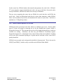
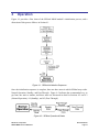
The I2C host interface supports both a read sequence using repeated START conditions,
shown in Figure 3-3, and a sequence in which the register address is sent in a separate
sequence than the data, shown in Figure 3-4.
START
SLAVE ADDRESS
RW ACK
S
A6 A5 A4 A3 A2 A1 A0
0
0
REGISTER ADDRESS (N)
ACK START
A7 A6 A5 A4 A3 A2 A1 A0
0
SR
SLAVE ADDRESS
RW ACK
A6 A5 A4 A3 A2 A1 A0 1
0
DATA FROM REGISTER (N)
A7 A6 A5 A4 A3 A2 A1 A0
Data Transferred
(n bytes + acknowledge)
Figure 3-3: I2C Slave Read Example, with Repeated START
START
S
SLAVE ADDRESS
RW ACK
A6 A5 A4 A3 A2 A1 A0 1
0
DATA FROM REG. (N)
ACK
DATA FROM REG. (N+1)
A7 A6 A5 A4 A3 A2 A1 A0
0
A7 A6 A5 A4 A3 A2 A1 A0
NACK STOP
1
P
From Host to SENtral
-------------- Data Transferred (n bytes + acknowledge) -------------From SENtral to Host
Figure 3-4: I2C Slave read register from current address
3.3 I2C Sensor Interface (Sensor Bus)
The SENtral motion coprocessor on the SENtral M&M module communicates with the
module’s accelerometer, gyroscope, and magnetometer over the module’s sensor bus, where
SENtral acts as the I2C master and the sensors act as I2C slave devices. Understanding how
the sensor bus operates is not necessary when using the SENtral M&M module, but it may be
useful if operating in Pass-Through state to communicate directly with a sensor or the
EEPROM.
PNI Sensor Corporation
SENtral M&M Technical Datasheet
Doc #1020129 rD
Page 11
NACK STOP
1
P
On the sensor bus, SENtral initiates data transfer and generates the serial clock. SENtral’s
I2C sensor interface supports Standard mode with a rate up to 100 kbit/s, Fast mode with a
rate up to 400 kbit/s, and Fast Plus mode with a rate up to 1000 kbit/s.
The two wires comprising the sensor bus are SDAM, the serial data line, and SCLM, the
serial clock. Both are bidirectional and driven by open drain transistors within SENtral.
These can be monitored by the host, but should not be written to by the host. Each line is
attached to a 4.7 kΩ pull-up resistor.
3.4 Host Interrupt/GPIO Lines
GPIO[6] provides an interrupt to the host whenever a defined event occurs. Exactly which
types of events will trigger an interrupt are set by the EnableEvents register, which is
discussed in Section 4.2 This interrupt line can be used to signal the host that new results are
available for reading. Alternately, the host may poll SENtral’s EventStatus register,
discussed in Section 4.3, to determine if any events of interest have been updated. If polling
will be used, PNI recommends polling on a regular interval such that an error event will be
quickly identified.
GPIO[4] is not currently used, and generally should be left unconnected. This is also true for
GPIO[3] and GPIO[5], which are only accessible on the SENtral White M&M.
PNI Sensor Corporation
SENtral M&M Technical Datasheet
Doc #1020129 rD
Page 12
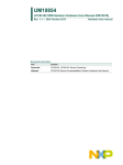
4
Operation
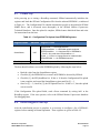
Figure 4-1 provides a flow chart of the SENtral M&M module’s initialization process, and a
discussion of this process follows in Section 4.1
Figure 4-1: SENtral Initialization Sequence
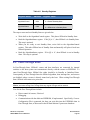
Once the initialization sequence is complete, there are three states in which SENtral may reside:
Normal Operation, Standby, and Pass-Through. Figure 4-2 indicates the recommended way to
get from one state to another, and these states are discussed in detail in Sections 4.2 and 4.3
(Normal Operation), 4.4 (Standby), and 4.5 (Pass-Through).
Figure 4-2: SENtral Operational States
PNI Sensor Corporation
SENtral M&M Technical Datasheet
Doc #1020129 rD
Page 13
4.1 Power-Up
After powering up or issuing a ResetReq command, SENtral automatically initializes the
registers and loads the SENtral Configuration File from the onboard EEPROM., as indicated
in Figure 4-1. The Configuration File contains information specific to the particular SENtral
M&M flavor, and is discussed more thoroughly in the SENtral Motion Coprocessor
Technical Datasheet. Once the upload is complete, SENtral enters Initialized State and waits
for instructions from the host.
Table 4-1: Configuration File Upload from EEPROM Registers
Register Name
Address
Register Value
SentralStatus
0x37
[0] EEPROM. 1 = EEPROM detected
[1] EEUploadDone. 1 = EEPROM upload completed
[2] EEUploadError. 1 = Calculated CRC of EEPROM is
correct. Only valid when EEUploadDone = 1.
[3] Idle. 1 = Device in Unprogrammed or Initialized state.
[4] NoEEPROM. 1 = No EEPROM detected.
ResetReq
0x9B
[0] ResetRequest. 1 = Emulate a hard power down/power up.
The host should confirm a successful EEPROM upload by following the steps below:
Read the value from the SentralStatus register.
Check bit [0], the EEPROM bit, to ensure an EEPROM is detected by SENtral.
Check bit [1], the EEUploadDone bit. If this is ‘0’ then the Configuration File upload
is not complete, and reread the SentralStatus register until bit [1] = 1.
Once bit [1] = 1, check bit [2], the EEUpload Error bit. If this is ‘0’, then the upload
was successful.
If the Configuration File upload failed, send a Reset command by writing 0x01 to the
ResetReq register. If the issue persists, refer to the SENtral Motion Coprocessor datasheet
for debugging hints.
4.2 Initial Register Set-Up
After the initialization process is complete, it is necessary to configure a few of SENtral’s
registers before running in Normal Operation. These registers are given in Table 4-2.
PNI Sensor Corporation
SENtral M&M Technical Datasheet
Doc #1020129 rD
Page 14
Table 4-2: Registers for Initial Set-up
Register Name
Address
Register Value
MagRate
0x55
Requested magnetometer output data rate
AccelRate
0x56
Requested accelerometer output data rate divided by 10
GyroRate
0x57
Requested gyroscope output data rate divided by 10
QRateDivisor
0x32
Along with GyroRate, establishes output data rate for
quaternion data.
0x54
[0] 1 = StandbyEnable
0 = Disable Standby State
[1] RawDataEnable. 1 = Raw data provided in MX, MY,
MZ, AX, AY, AZ, GX, GY, & GZ.
0 = Scaled sensor data.
[2] HPRoutput. 1 = Heading, pitch, and roll output in QX,
QY, & QZ. QW = 0.0.
0 = Quaternion outputs.
0x33
‘1’ indicates an interrupt to the host will be generated for
the event.
[0] CPUReset. Non-maskable
[1] Error
[2] QuaternionResult
[3] MagResult
[4] AccelResult
[5] GyroResult
AlgorithmControl
EnableEvents
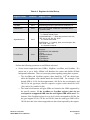
Perform the following operations to run SENtral as desired.
Set the sensor output data rates (ODRs): MagRate, AccelRate, and GyroRate. If a
sensor rate is set to 0x00, SENtral will shutdown the sensor and disable SENtral
background calibration. There are two major points regarding setting these registers:
o The AccelRate and GyroRate register values should be 1/10th the desired rate,
while the MagRate value should match the desired ODR. For example, if the
desired ODR is 30 Hz for the magnetometer, 100 Hz for the accelerometer, and
200 Hz for the gyroscope, then the respective register values should be 0x1E
(30d), 0x0A (10d), and 0x14 (20d).
o The actual accelerometer and gyro ODRs are limited to the ODRs supported by
the specific sensors. If the AccelRate or GyroRate register values do not
correspond to a supported ODR, then the next highest ODR will be used. For
instance, if the GyroRate register is set to 0x14, which corresponds to 200 Hz, but
the gyro supports 95 Hz, 190 Hz, and 380 Hz, then the actual gyro ODR will be
380 Hz since this is the closest supported rate above that requested by the register.
PNI Sensor Corporation
SENtral M&M Technical Datasheet
Doc #1020129 rD
Page 15
Establish the quaternion output data rate, where the quaternion output data rate equals
GyroRate divided by QRateDivisor. The default for QRateDivisor is 0x00, which is
interpreted as ‘1’ and results in the quaternion output data rate equaling GyroRate.
Establish how SENtral’s orientation and sensor data is to be output. The
AlgorithmControl register allows the user to select either quaternion or Euler angles
(heading, pitch, and roll) for orientation outputs, and either scaled or raw sensor data
outputs. The defaults are quaternions and scaled sensor data.
Establish which events will trigger an interrupt to the host by configuring the
EnableEvent register. PNI specifically recommends enabling bit [1], the Error
interrupt bit, in addition to whichever other interrupts the user wants.
Example steps to do this are below:
Write 0x640A0F to the MagRate register. Since SENtral automatically increments to
the next register, this also populates the AccelRate and GyroRate registers. This sets
MagRate to 100 Hz, AccelRate to 100 Hz, and GyroRate to 150 Hz.
Write 0x01 to the QRateDivisor Register. This sets the quaternion output data rate to
equal the GyroRate. This step is optional, since the default register value of 0x00
also sets the quaternion output data rate equal to GyroRate.
Write 0x06 to the AlgorithmControl register. This enables heading, pitch, and roll
orientation outputs and raw sensor data outputs. This step is optional, as the default
register value of 0x00 results in outputs of quaternions and scaled sensor data.
Write 0x07 to the EnableEvents register. This sets the host to receive interrupts from
SENtral whenever the quaternion results registers (QX, QY, QZ, and QW) are
updated, an error has been detected, or SENtral has been Reset but the Configuration
File has not been uploaded. If the host will regularly poll SENtral, rather than run in
an interrupt-driven manner, it is not necessary to set the EnableEvents register.
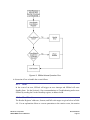
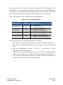
4.3 Running in Normal Operation
After performing the steps listed above, SENtral is ready to start generating orientation data.
The registers used to run in Normal Operation are given in Table 4-2, the steps to follow
comes after this, and a flow diagram is given in Figure 4-3.
PNI Sensor Corporation
SENtral M&M Technical Datasheet
Doc #1020129 rD
Page 16
Table 4-3: Normal Operation Registers
Register Name
Address
HostControl
EventStatus
Register Value
0x34
[0] 1 = RunEnable
0 = Enable Initialized State
0x35
‘1’ indicates a new event has been generated.
[0] CPUReset
[1] Error
[2] QuaternionResult
[3] MagResult
[4] AccelResult
[5] GyroResult
Below are the steps to follow when operating in Normal Operation state.
a) Write 0x01 to the HostControl register. This sets the RunEnable bit to ‘1’ and
enables the sensors and the SENtral algorithm.
b) If operating in an interrupt-driven mode, then the host waits until it receives an
interrupt signal from SENtral. Alternatively the host may operate on a polling basis,
rather than an interrupt-driven basis, in which case the interrupt line may not be used.
c) Once an interrupt is received by the host or the host otherwise decides to read new
data, read the EventStatus register.
d) Interpret and act on the EventStatus register in the priority shown in Figure 4-3. If bit
[1], the Error bit, is ‘1’, see Section 4.3.1. If bits [2], [3], [4], or [5], the Results bits,
are ‘1’, see Section 4.3.2. Bit [0], the CPUReset bit, should never be ‘1’, since this
bit only can be ‘1’ after a Reset or powering up and prior to loading the Configuration
File, and on the SENtral M&M module loading of the Configuration File is
automatically performed after powering up.
e) Repeat steps c and d until new orientation data is not needed and/or the host decides
to enter a different state.
Reading the EventStatus register clears it. It is possible for more than one bit position to
be ‘1’ in the EventStatus register, especially if the host does not always read the EventStatus
register after receiving an interrupt. Similarly, if multiple bits are set to ‘1’ in the
EventStatus register, once the register is read all the bits will be set to ‘0’. For this reason the
EventStatus register should be processed in the priority shown in Figure 4-3, as information
will be cleared for events that are not handled.
PNI Sensor Corporation
SENtral M&M Technical Datasheet
Doc #1020129 rD
Page 17
Figure 4-3: SENtral Normal Operation Flow
A discussion of how to handle the events follows.
4.3.1
Error
In the event of an error, SENtral will trigger an error interrupt and SENtral will enter
Standby State. See the Section 4.6 for recommendations on Troubleshooting and/or reset
SENtral by sending 0x01 to the ResetReq register, at address 0x9B.
4.3.2
Read Results
The Results Registers’ addresses, formats, and full-scale ranges are given below in Table
4-4. For an explanation of how to convert quaternions to the rotation vector, the rotation
PNI Sensor Corporation
SENtral M&M Technical Datasheet
Doc #1020129 rD
Page 18
matrix, or Euler angles (heading, pitch, and roll), see Appendix I. The resolution is
32 kHz for all timestamps.
Note: All multi-byte elements are stored and transmitted using the Little Endian convention: the
2
least significant byte is stored at the lowest address and transmitted first over the I C bus.
Table 4-4: Results Registers
Name
Address
(Hex)
Description
Format
Full-Scale Range
QX
00 – 03
Normalized Quaternion – X, or Heading
Float32
0.0 – 1.0, or ±
QY
04 – 07
Normalized Quaternion – Y, or Pitch
Float32
0.0 – 1.0, or ±/2
QZ
08 – 0B
Normalized Quaternion – Z, or Roll
Float32
0.0 – 1.0, or ±
QW
0C – 0F
Normalized Quaternion – W, or 0.0
Float32
0.0 – 1.0
QTime
10 – 11
Quaternion Data Timestamp
UInt16
0 – 2048 msec
MX
12 – 13
Magnetic Field – X Axis, or Raw Mag Data
Int16
±1000 µT when scaled
MY
14 – 15
Magnetic Field – Y Axis, or Raw Mag Data
Int16
±1000 µT when scaled
MZ
16 – 17
Magnetic Field – Z Axis, or Raw Mag Data
Int16
±1000 µT when scaled
MTime
18 – 19
Magnetometer Interrupt Timestamp
UInt16
0 – 2048 msec
AX
1A – 1B
Linear Acceleration – X Axis, or Raw Accel Data
Int16
±16 g when scaled
AY
1C – 1D
Linear Acceleration – Y Axis, or Raw Accel Data
Int16
±16 g when scaled
AZ
1E – 1F
Linear Acceleration – Z Axis, or Raw Accel Data
Int16
±16 g when scaled
ATime
20 – 21
Accelerometer Interrupt Timestamp
UInt16
0 – 2048 msec
GX
22 – 23
Rotational Velocity – X Axis, or Raw Gyro Data
Int16
±5000°/s when scaled
GY
24 – 25
Rotational Velocity – Y Axis, or Raw Gyro Data
Int16
±5000°/s when scaled
GZ
26 – 27
Rotational Velocity – Z Axis, or Raw Gyro Data
Int16
±5000°/s when scaled
GTime
28 – 29
Gyroscope Interrupt Timestamp
UInt16
0.0 – 2.048 sec
4.4 Standby State
In Standby State overall system power consumption is dramatically reduced because both the
SENtral algorithm and the sensors are shut down. Table 4-5 provides the registers associated
with Standby State.
PNI Sensor Corporation
SENtral M&M Technical Datasheet
Doc #1020129 rD
Page 19
Table 4-5: Standby Registers
Register Name
Address
Register Value
AlgorithmControl
0x54
[0] 1 = StandbyEnable
0 = Disable Standby State
AlgorithmStatus
0x38
[0] 1 = SENtral in Standby State
0 = SENtral not in Standby State
The steps to enter and exit Standby State are given below:
Write 0x01 to the AlgorithmControl register. This places SENtral in Standby State.
Read the AlgorithmStatus register. If bit [0] is ‘1’, then SENtral is in Standby State.
This step is optional.
When you are ready to exit Standby State, write 0x00 to the AlgorithmControl
register. This takes SENtral out of Standby State and normally will place it back into
Normal Operation.
Read the AlgorithmStatus register. If bit [0] is ‘0’, then SENtral is not in Standby
State. This step is optional.
4.5 Pass-Through State
In Pass-Through State, SENtral’s sensor and host interfaces are connected by internal
switches so the host system can communicate directly with the sensors or EEPROM. To
enter Pass-Through State, SENtral first either should be in Standby or Initialized State.
Consequently, in Pass-Through State the SENtral algorithm, host interrupt line, and sensors
are disabled, unless a sensor is directly turned on by the host. When exiting Pass-Through
State, SENtral will return to its prior state.
Note: When entering Pass-Through State the sensor’s registers retain the values established by
SENtral, and when exiting Pass-Through State any register changes will be retained.
Uses for the Pass-Through State include:
Direct control of sensors, if desired.
Debugging.
Communication with the dedicated EEPROM, if implemented. Specifically, if a new
Configuration File is generated, the host can write this into the EEPROM when in
Pass-Through State, as discussed in the SENtral Motion Coprocessor datasheet.
PNI Sensor Corporation
SENtral M&M Technical Datasheet
Doc #1020129 rD
Page 20
Since operating in Pass-Through State requires stopping the SENtral algorithm, PassThrough State is not recommended for accessing sensor data unless reliable heading data is
not required. If sensor data and reliable heading data are both desired, they can both be
accessed during Normal Operation from the Results Registers, as given in Table 4-4.
Table 4-6 provides the registers associated with Pass-Through State.
Table 4-6: Pass-Through Registers
Register Name
Address
Register Value
AlgorithmControl
0x54
[0] 1 = StandbyEnable
0 = Disable Standby State
AlgorithmStatus
0x38
[0] 1 = SENtral in Standby State
0 = SENtral not in Standby State
PassThroughControl
0xA0
[0] 1 = Enable Pass-Through State
0 = Disable Pass-Through State
PassThroughStatus
0x9E
[0] 1 = SENtral in Pass-Through State.
0 = SENtral not in Pass-Through State.
The steps to go in and out of Pass-Through State are given below.
Write 0x01 to the AlgorithmControl register. This places SENtral in Standby State.
Write 0x01 to the PassThroughControl register. This places SENtral in Pass-Through
State.
Read the PassThroughStatus register. If bit [0] is ‘1’, then SENtral is in PassThrough State. This step is optional.
When you are done in Pass-Through State, write 0x00 to the PassThroughControl
register. This terminates Pass-Through mode and returns SENtral to Standby State.
Write 0x00 to the AlgorithmControl register. This takes SENtral out of Standby State
and normally will place it back into Normal Operation.
PNI Sensor Corporation
SENtral M&M Technical Datasheet
Doc #1020129 rD
Page 21
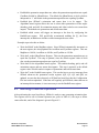
4.6 Troubleshooting
This section provides guidance in troubleshooting SENtral, and is divided into hardwarerelated and software-related errors.
4.6.1
Hardware-Related Error Conditions
Possible indications of a hardware-related problem are given below in Table 4-7.
Table 4-7: Hardware-Related Error Indications
Register Name
Address
Error Indication
EventStatus
0x35
[0] 1 = CPURest. SENtral Configuration
File needs uploading. See Section 4.1.
SentralStatus
0x37
[2] 1 = EEUploadError. Issue with
uploading from the dedicated EEPROM.
See Section 4.1.
MagRate
0x55
0x00 – Value lost
AccelRate
0x56
0x00 – Value lost
GyroRate
0x57
0x00 – Value lost
In the event of such errors, SENtral will enter Standby State, shut down the sensors, and
generate an interrupt to the host. Possible reasons for hardware-related errors include
problems with the EEPROM upload, power transients detected by power management,
and errors in software detected by Watchdog. Often the error can be cleared by sending
the ResetReq command.
PNI Sensor Corporation
SENtral M&M Technical Datasheet
Doc #1020129 rD
Page 22
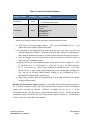
4.6.2
Software-Related Error Conditions
Possible indications of software-related errors are given below in Table 4-8:
Table 4-8: Software-Related Error Indications
Register Name
Address
EventStatus
0x35
SensorStatus
0x36
Error Indication
[1] 1 = Error.
[0] MagNACK. 1 = NACK from magnetometer
[1] AccelNACK. 1 = NACK from accelerometer
[2] GyroNACK. 1 = NACK from gyroscope
[4] MagDeviceIDErr. 1 = Unexpected DeviceID from
magnetometer
[5] AccelDeviceIDErr. 1 = Unexpected DeviceID from
accelerometer
[6] GyroDeviceIDErr. 1 = Unexpected DeviceID from
gyroscope.
SentralStatus
0x37
[3] 1 = Idle. SENtral in Initialized State.
ErrorRegister
0x50
Non-zero value indicated an error. See Table 4-9.
If the ErrorRegister indicates a non-zero value, then the value provides additional
information on the sensor that is causing a problem, as given in Table 4-9.
Table 4-9: ErrorRegister Indications
Value
Error Condition
Response
0x00
No error
0x80
Invalid sample rate selected
Check sensor rate settings.
0x30
Mathematical Error
Check for software updates
0x21
Magnetometer initialization failed
0x22
Accelerometer initialization failed
0x24
Gyroscope initialization failed
This error can be caused by a wrong
driver, physically bad sensor
2
connection, or incorrect I C device
address in the driver
0x11
Magnetometer rate failure
0x12
Accelerometer rate failure
0x14
Gyroscope rate failure
PNI Sensor Corporation
SENtral M&M Technical Datasheet
This error indicates the given sensor
is unreliable and has stopped
producing data.
Doc #1020129 rD
Page 23
5
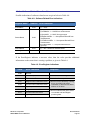
Package Information
Figure 5-1: SENtral Orange, Red, Green, & Yellow M&M Mechanical Drawing
Figure 5-2: SENtral White M&M Mechanical Drawing
PNI Sensor Corporation
SENtral M&M Technical Datasheet
Doc #1020129 rD
Page 24
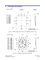
Figure 5-3: SENtral Blue M&M Mechanical Drawing
PNI Sensor Corporation
SENtral M&M Technical Datasheet
Doc #1020129 rD
Page 25
6
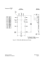
Assembly Guidelines
Figure 6-1: SENtral Orange, Red, Green, & Yellow M&M Solder Pad Layout
Figure 6-2: SENtral White M&M Solder Pad Layout
PNI Sensor Corporation
SENtral M&M Technical Datasheet
Doc #1020129 rD
Page 26
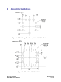
Figure 6-3: SENtral Blue M&M Solder Pad Layout
PNI Sensor Corporation
SENtral M&M Technical Datasheet
Doc #1020129 rD
Page 27
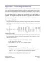
Appendix I – Converting Quaternions
SENtral outputs orientation data in quaternions, using a North-East-Down (NED) convention.
This is done to avoid the singularities inherent in using Euler angles (heading, pitch, and roll),
and because the fusion algorithms are easier to implement with quaternions. However, normally
quaternions are not the desired final output format. Most end users will want heading, pitch, and
roll, while Android looks for a rotation vector and generally uses a rotation matrix for
orientation. Plus, Android and Win8 both expect data to be presented in the East-North-Up
(ENU) convention. This appendix discusses how to convert SENtral’s output quaternions into
these other output formats.
Converting from NED to ENU
While the North-East-Down (NED) convention is common in many industries, both Android
and Windows 8 use the East-North-Up convention. Below is the equation to convert from
NED to ENU.
Heading, Pitch, and Roll
Most end users will want orientation data reported as heading, pitch, and roll. Below are the
Excel transformation equations. Note that for other programs, such as Matlab, the ATAN2
arguments may be reversed.
Heading = atan2[(Qx2 – Qy2 – Qz2 + Qw2), 2*(QxQy + QzQw)]
Pitch = asin[-2*(QxQz – QyQw)]
Roll = atan2[(–Qx2 – Qy2 + Qz2 + Qw2), 2*(QxQw + QyQz)]
Where:
Results are in radians.
The quaternions are the outputs from SENtral in NED convention.
Heading increases as the device rotates clockwise around a positive Z axis, and the
range is 0° – 360°. (i.e. it matches what you would expect on a compass.)
Pitch increases when pitching upward and the range is ±180°.
Roll increases when rolling clockwise and the range is ±90°.
PNI Sensor Corporation
SENtral M&M Technical Datasheet
Doc #1020129 rD
Page 28
Rotation Vector
The rotation vector is the first three elements of the quaternion output, Qx, Qy, and Qz. The
fourth element, Qw, is not included in the rotation vector. The rotation vector in ENU
convention will be the first three elements of QENU, discussed above.
Rotation Matrix, or Direction Cosine Matrix (DCM)
The rotation matrix, also known as the direction cosine matrix (DCM), can be established
from the quaternion output using the following conversion. QENU values can be substituted
to give the rotation matrix with an ENU convention.
2
2
2
2
Qw + Qx – Qy – Qz
R=
2*(Qx*Qz – Qw*Qy)
2*(Qx*Qy + Qw*Qz)
2
2
2
2
2*(Qx*Qy – Qw*Qz)
Qw – Qx + Qy – Qz
2*(Qy*Qz + Qw*Qy)
2*(Qx*Qz + Qw*Qy)
2*(Qy*Qz – Qw*Qy)
Qw – Qx – Qy + Qz
PNI Sensor Corporation
SENtral M&M Technical Datasheet
2
2
2
2
Doc #1020129 rD
Page 29
Appendix II – Measuring Current Consumption
All SENtral M&M modules, except the White and Blue versions, have two distinct electrical
supply lines. One line is for both the EEPROM and the sensors, and one is for just SENtral. The
pins for these voltages are labeled DVDD and DVDD2, respectively. To measure the current on
these lines, PNI recommends placing a 1 Ω resistor in series with the DVDD pin to measure
combined current consumption for the EEPROM and sensors, and a 100 Ω resistor in series with
the DVDD2 pin to measure current consumption by SENtral.
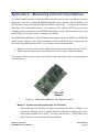
The SENtral Blue M&M has a single DVDD pin that supplies current for SENtral, the EEPROM
and the sensors. However, the current consumption of only the SENtral motion coprocessor can
be measured by modifying the module, as given in the two options listed below.
1. Replace a zero-ohm resistor with a 100Ω resistor and measure voltage across the resistor.
2. Remove the zero-ohm resistor, then solder wires in series with a connected ammeter.
The location of the zero-ohm resistor is given below, and a discussion of the two implementation
methods follows.
Figure A-1: SENtral Blue M&M Zero-Ohm Resistor Location
Method 1: Replace zero-ohm resistor with 100 Ω resistor.
This method provides flexibility in terms of measuring with either a voltmeter or an
oscilloscope, although it may be slightly difficult to implement as holding the probes
in the proper position can be tricky. As long as the resistor is ≤100 Ω, there is no
need to remove it, as it should not affect performance.
PNI Sensor Corporation
SENtral M&M Technical Datasheet
Doc #1020129 rD
Page 30
To measure average current consumption, simply touch either side of the 100 Ω
resistor with the voltmeter’s probe tips and measure the voltage drop. Convert to
current consumption using: A = 10*mV, assuming a 100 Ω resistor.
It is possible to observe the current consumption waveform using an oscilloscope. In
this case, place a 100 F capacitor in parallel with the 100 Ω resistor. This reduces
the measurement bandwidth so the waveform can be better observed.
Note that SENtral’s bypass capacitors are electrically connected nearest the device
after the sense resistor or the voltage meter’s resistor. This will bandlimit the
measurement to ~1.5 kHz for a 100 Ω resistor. The onboard bypass capacitance
totals 1.1 F.
Method 2: Remove zero-ohm resistor and place ammeter in series.
This method is relatively straight forward to implement, as the probes are physically
soldered to the PCB. To help prevent damage to the PCB surface pads, PNI strongly
recommends implementing a strain relief for the wires.
Note that the burden voltage of a typical digital multimeter (ammeter) is ~100V/A,
or 100 Ω. PNI has tested such an ammeter in the Method 2 scenario and seen that it
does not affect operation. Also note that negative voltages produced by transient
currents are smoothed by the local bypass capacitors.
Also, it may be difficult to measure DC current using ammeters with very fast
measurement times due to the periodic wake/sleep cycles of SENtral. Consequently,
handheld DMMs with relatively long measurement integration times work well for
making average current measurement. Precision benchtop meters with an averaging
or smoothing filter also can work well.
PNI Sensor Corporation
SENtral M&M Technical Datasheet
Doc #1020129 rD
Page 31
©2013 PNI Sensor Corporation. All Rights Reserved.
Reproduction, adaptation, or translation without prior written permission is prohibited, except as allowed under copyright laws.
Revised January 2014: for the most recent version visit our website at www.pnicorp.com
PNI Sensor Corporation
2331 Circadian Way
Santa Rosa, CA 95407, USA
Tel: (707) 566-2260
Fax: (707) 566-2261
Warranty and Limitation of Liability. PNI Sensor Corporation ("PNI") manufactures its Products from parts and components that
are new or equivalent to new in performance. PNI warrants that each Product to be delivered hereunder, if properly used, will, for
ninety (90) days following the date of shipment unless a different warranty time period for such Product is specified: (i) in PNI’s Price
List in effect at time of order acceptance; or (ii) on PNI’s web site (www.pnicorp.com) at time of order acceptance, be free from
defects in material and workmanship and will operate in accordance with PNI’s published specifications and documentation for the
Product in effect at time of order. PNI will make no changes to the specifications or manufacturing processes that affect form, fit, or
function of the Product without written notice to the Customer, however, PNI may at any time, without such notice, make minor
changes to specifications or manufacturing processes that do not affect the form, fit, or function of the Product. This warranty will be
void if the Products’ serial number, or other identification marks have been defaced, damaged, or removed. This warranty does not
cover wear and tear due to normal use, or damage to the Product as the result of improper usage, neglect of care, alteration,
accident, or unauthorized repair.
THE ABOVE WARRANTY IS IN LIEU OF ANY OTHER WARRANTY, WHETHER EXPRESS, IMPLIED, OR STATUTORY,
INCLUDING, BUT NOT LIMITED TO, ANY WARRANTY OF MERCHANTABILITY, FITNESS FOR ANY PARTICULAR PURPOSE,
OR ANY WARRANTY OTHERWISE ARISING OUT OF ANY PROPOSAL, SPECIFICATION, OR SAMPLE. PNI NEITHER
ASSUMES NOR AUTHORIZES ANY PERSON TO ASSUME FOR IT ANY OTHER LIABILITY.
If any Product furnished hereunder fails to conform to the above warranty, Customer’s sole and exclusive remedy and PNI’s sole
and exclusive liability will be, at PNI’s option, to repair, replace, or credit Customer’s account with an amount equal to the price paid
for any such Product which fails during the applicable warranty period provided that (i) Customer promptly notifies PNI in writing that
such Product is defective and furnishes an explanation of the deficiency; (ii) such Product is returned to PNI’s service facility at
Customer’s risk and expense; and (iii) PNI is satisfied that claimed deficiencies exist and were not caused by accident, misuse,
neglect, alteration, repair, improper installation, or improper testing. If a Product is defective, transportation charges for the return of
the Product to Customer within the United States and Canada will be paid by PNI. For all other locations, the warranty excludes all
costs of shipping, customs clearance, and other related charges. PNI will have a reasonable time to make repairs or to replace the
Product or to credit Customer’s account. PNI warrants any such repaired or replacement Product to be free from defects in material
and workmanship on the same terms as the Product originally purchased.
Except for the breach of warranty remedies set forth herein, or for personal injury, PNI shall have no liability for any indirect or
speculative damages (including, but not limited to, consequential, incidental, punitive and special damages) relating to the use of or
inability to use this Product, whether arising out of contract, negligence, tort, or under any warranty theory, or for infringement of any
other party’s intellectual property rights, irrespective of whether PNI had advance notice of the possibility of any such damages,
including, but not limited to, loss of use, revenue or profit. In no event shall PNI’s total liability for all claims regarding a Product
exceed the price paid for the Product. PNI neither assumes nor authorizes any person to assume for it any other liabilities.
Some states and provinces do not allow limitations on how long an implied warranty lasts or the exclusion or limitation of incidental
or consequential damages, so the above limitations or exclusions may not apply to you. This warranty gives you specific legal rights
and you may have other rights that vary by state or province.
PNI Sensor Corporation
SENtral M&M Technical Datasheet
Doc #1020129 rD
Page 32