1
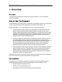
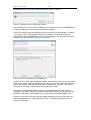
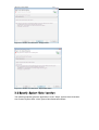
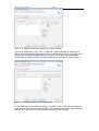
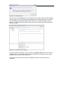
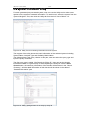
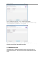
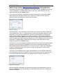
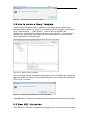
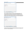
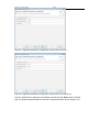
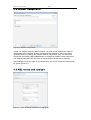
Alborz 1.0 User Guide
October 10, 2007
Feng Xiao
[email protected]
Alborz 1.0 User Guide
1/37
Document Revision History
Rev. Level
Important
Date
2007/10/10
Description
Initial Version
Reference Documents
Document #
#01
Description
Alborz 1.0 Installation Guide
Alborz 1.0 User Guide
2/37
Contents
Contents ....................................................................................................................2
1
Overview .................................................................................................................4
Purpose ......................................................................................................................4
How to Use This Document........................................................................................4
Assumptions ...............................................................................................................4
2
3
4
System Data Generation Wizard ............................................................................5
2.1
Select Extractor................................................................................................5
2.2
Specify System Data Location .........................................................................7
2.3
Define Mapping between Nodes......................................................................9
2.4
Define Mapping between Edges ....................................................................11
2.5
Select Data Mining Algorithm.........................................................................13
2.6
Set Data Mining Algorithm parameters..........................................................13
2.7
Perform Data Mining ......................................................................................14
2.8
System Information Utility ..............................................................................17
Query Template Generation Wizard.....................................................................19
3.1
Set query parameters.....................................................................................19
3.2
Edit Components............................................................................................20
3.3
How to delete a Query Template ...................................................................24
3.4
View AQL information ....................................................................................24
System Analyzing Wizard .....................................................................................26
4.1
Search algorithm selection.............................................................................26
4.2
Algorithm parameters configuration ...............................................................26
4.3
Reorder components......................................................................................29
4.4
AQL review and analysis................................................................................29
4.5
Main seeds suggestion ..................................................................................31
4.6
Nodes distribution ..........................................................................................33
4.7
Completing page and ShriMP Tool ................................................................34
Alborz 1.0 User Guide
4.8
3/37
Others.............................................................................................................35
Alborz 1.0 User Guide
4/37
1 Overview
Purpose
This document provides the operational manual for Alborz 1.0 on all supported
operating systems.
How to Use This Document
The information in this user guide, as outlined in the Table of Contents, is divided into
sections corresponding to the organization of functions within Alborz 1.0.
When using Alborz 1.0, 3 major phases need to be completed in order:
1. The first phase is called ‘System Data Generation’. In this phase, the user
defines a pre-processed system (target system) including: system name,
location of the target system, level of analysis (i.e., file-level or function-level),
mapping the information obtained from the target system to the format used
by Alborz, and data mining algorithm. All these information can be set by
using the System Data Generation Wizard.
2. The second phase is called ‘Query Template Generation’. Based on the preprocessed target system generated in the first phase, the user defines a
query template that will be used and customized during the analysis phase. In
the query template, the user defines the query name, number and detail
information about all components that will in the AQL query. The query
template is defined using the Query Template Generation Wizard.
3. The last phase is called ‘System Analysis’. Based on the template information
which is defined in Query Template Wizard, we can analyze the system by
defining Analysis Type and Algorithm, setting algorithm parameters and
adjusting the order and content of components. All these can be completed
through the System Analyzing Wizard.
Additional information concerning common tasks, how certain parts of the application
work, and resources and tools is provided in the appendices.
Assumptions
In addition to the instructions outlined in this manual, it is assumed that anyone
installing Alborz should have working knowledge of and/or experience with:
•
Using Eclipse as development tool
•
Installing and using Eclipse plug-ins
•
Knowledge about Reverse Engineering and Data Mining
Alborz 1.0 User Guide
5/37
2 System Data Generation Wizard
The main frame of Alborz 1.0 is shown in Figure 2.1 below:
Figure 2.1. Main Frame of Alborz 1.0
To generate a new Pre-processed system, the user should run the System Data
Generation Wizard first by clicking the icon
in the System Navigator view, or by
clicking the link: click here to generate system data in the Info view of Alborz. After the
wizard is startup, the first step is to select the Fact Extractor and define the name for the
new pre-processed system.
2.1 Select Fact Extractor
Figure 2.2. Step 1, Select Fact Extractor
Alborz 1.0 User Guide
6/37
In this wizard, the user can select Cancel button at anytime to cancel the wizard. After
the Cancel button is selected, a dialog box will be shown as follow:
Figure 2.3. Dialog box when canceling the wizard
In this dialog box, user can click the Yes button to exit the wizard, or click the No button
to close the dialog box and continue working on the wizard.
In the Fact Extractor selection dropdown list two extractors can be selected. For Alborz
1.0, currently only the Refine Data Extractor is completed. If user selects the GXL
Extractor and clicks the Next button, then an error message: ’The Fact Extractor is not
available yet.’ will be shown on the top of the wizard.
Figure 2.4. GXL Fact Extractor is not available yet.
In step 1 of the System Data Generation Wizard, both the Fact Extractor and the system
name must be given before proceeding to the next step. If the user leave the text box for
system name empty, and click the Next button, then the error message: ”The system
name can not be empty.” will be shown on the top of the wizard.
If the system name already exists in the pre-processed systems list, then the error
message: “The system name [new system name] already exists!” will be shown on the
top of the wizard when user attempts to go to next step by clicking the Next button.
If both the Fact Extractor and the System Name are defined correctly, then after user
clicks the Next button the wizard will reach to step 2: System Data Generation from
Present System Data.
Alborz 1.0 User Guide
7/37
Figure 2.5. Select Fact Extractor: Empty Name
Figure 2.6. Select Fact Extractor: Duplicated Name
2.2 Specify System Data Location
The following snapshot gives the appearance of the “Step2: System Data Generation
from Present System Data” of the System Data Generation Wizard.
Alborz 1.0 User Guide
8/37
Figure 2.7. Select location
In this step, the user is required to provide the location of the present system data which
will be analyzed in the future. User can directly input the location string to the text box, or
use the browse button to select the position.
When user click the Next button, error messages will be shown on the top the wizard if
the user leaves the text box empty, or the location that user provided doesn’t exist, or the
location doesn’t contain correct system data files which are required by Alborz to analyze.
Figure 2.8. Select location with wrong path value
When the location is defined correctly, after user clicks the Next button, the wizard will
reach to step 3: Mapping between Types of graph nodes.
Alborz 1.0 User Guide
9/37
2.3 Define Mapping between Nodes
The following snapshot gives the appearance of the “step 3: Mapping between Types of
graph nodes” of the System Data Generation Wizard.
Figure 2.9. Mapping Nodes between Alborz and target system.
In this page, user needs to set the level of analyses (Node Granularity) and define the
mapping relation between node-types used in Alborz (Alborz Type) and node-types in the
target system (Input Type).
For the Node Granularity, the user can select Function or File level from the dropdown
list. The Similarity Matrix name is generated by Alborz automatically and can not be
changed. If the Node Granularity is Function, the Similarity Matrix name will be set to
‘SimMatrixFF’, otherwise the Similarity Matrix name will be “SimMatrixLL” representing
File Granularity level.
In Alborz 1.0, there are 4 types of entities: L (File), F (Function), T (Type with user defined
structure) and V (Global variable). The items in the dropdown list for the types of target
system data (Input Type) maybe different from those of Alborz because of different fact
extractor tools used for them.
After one mapping relation is chosen, user can click the Add button to add this mapping
relation to the mapping table. More than one mapping relations can be added to the
mapping table but duplicated type is not permitted. To delete one mapping relation from
the mapping table, user can select that row from the mapping table, and then click the
Delete button. In this page, at least one mapping relation should be defined in the
mapping table.
Alborz 1.0 User Guide
10/37
Figure 2.10. Mapping nodes with different types; Add and Delete
If the Node Granularity is set to “File”, L (File) and F (File) must exist for Node Type in
Alborz in the mapping table. Otherwise an error message will be shown on the top of the
wizard when user clicks the Next button of this page. At File level, Alborz generates
components consisting of Files that communicate (import and export) using Functions.
Figure: 2.11. Mapping Nodes; wrong mapping value
On the other hand, if the Node Granularity is “Function”, then L (File) can not appear as
Node Type for “Alborz” in the mapping table. This is because File level is higher than the
Function level and conflicts with the Node Granularity that user defined.
Alborz 1.0 User Guide
11/37
Figure 2.12. Mapping Nodes; wrong mapping value
After the node mapping relations are defined correctly and the Next button is selected,
the System Data Generation Wizard will reach to Step 4: Mapping between Types of
graph edges.
2.4 Define Mapping between Edges
In this page, user needs to set the mapping relation of edges between Alborz (Alborz
Type) and the target system data (Input Type).
In this page, the Node Granularity (Analyze level) is read-only and the value is defined in
the previous page.
For the edge types of Alborz, we can select from five values: Use-V (User Variable), UseF (Use Function), Use-T (Use Type), Use-R (Use Resource) and Contain-R (Contain
Resource). For the Input Type, the edges in the dropdown list maybe different from the
edges in Alborz since the system which will be analyzed may have different definitions for
the edge-types. Contain-R and Use-R are only available for File level analysis. Contain-R
means a file contains some resource such as (Variable, Type and Function). Use-R
means that Variable (global), Type (structure) or Function of other files have been used
by this file.
After one mapping relation is chosen, user can click the Add button to add this mapping
relation to the mapping table. More than one mapping relations can be added to the
mapping table but duplicated type is not permitted. To delete one mapping relation from
the mapping table, user can select that row from the mapping table, and then click the
Delete button. In this page, at least one mapping relation should be defined in the
mapping table.
Alborz 1.0 User Guide
12/37
Figure 2.13. Mapping edges
In the mapping table of this page, the values of edge types in Alborz should match with
the Nodes types in Alborz in the previous page. For example, if user has defined F, V or T
for Node types of Alborz in the previous page, then the mapping relation table must
contain Use-F, Use-T or Use-V in the Edge types of Alborz. If this condition is not
satisfied, then an error message will be shown on the top of the wizard when user clicks
the Next button.
Figure 2.14. Mapping Edges: Wrong mapping value
After the mapping relations are defined correctly, the user can click Next button to reach
to the next page of System Data Generation Wizard: Step 5: Select Data Mining
Algorithm.
Alborz 1.0 User Guide
13/37
2.5 Select Data Mining Algorithm
In the Select Data Mining Algorithm page, user needs to select the Data Ming algorithm.
In Alborz 1.0, only one algorithm called Apriori is provided.
Figure 2.15. Select Data Ming Algorithm
After the data mining algorithm is select from the dropdown list, click the Next button to
go to the next step: Step 6: Data Mining Parameters.
2.6 Set Data Mining Algorithm parameters
In the Data mining parameters page, the user needs to set parameter-values for Apriori
algorithm. Apriori algorithm uses min-support and itemset size to control the number of
relations and running time to generate the similarity matrix. A high Min-support value
reduces the number of relations, and a low Max Itemset value stops data mining
algorithm before completion. An exception is that if Max Itemset is set to 0, then the
algorithm will not be constrained by the size of itemset and the Apriori algorithm will be
completed.
After one pair of parameters is input, user can click the Add button to add this pair to the
parameters table. More than one pair of parameters can be added to the parameter table.
To delete one pair of parameters from the parameter table, the user can select that row
from the table, and then click the Delete button. In this page, at least one pair of
parameters should be defined in the parameter table.
In the parameter table, each pair of parameters (each row) is called one Pass. For each
pass, the Apriori algorithm will run once based on the parameter-values of this pass. So if
there are more than one Passes in the parameter table, the Apriori algorithm will run
multiple times automatically, and each time the algorithm will use one pair of parameters’
values from the parameter table orderly. This is intended to generate more association
relations, as follows. For example, the first pair of parameters has high min-support then
many association relations are cancelled, however the Apriori algorithm will complete in a
reasonable time. The second (or third) pair then generates many association relations
(having low min-support) but the algorithm terminates before completion to prevent
extensive time requirements.
Alborz 1.0 User Guide
14/37
Figure 2.16. Setting parameters for data mining algorithm.
After the parameters of data mining algorithm are set, then user can click Finish button
to start the data mining process.
2.7 Perform Data Mining
Figure: 2.17 Perform Data Mining
After the Finish button is clicked, the Data Mining process will be started. The data
mining algorithm may take a long time depends on the size of system and the values of
parameters.
After the data mining process is finished, a message box will be shown.
Alborz 1.0 User Guide
15/37
Figure 2.18. Wizard finished
After the user click the OK button, the message box the System Data Generation Wizard
will be closed, and a user defined pre-processed system will be generated successfully.
The generated pre-processed system will be shown in the System Navigator view of
Alborz 1.0. User can click the system name to extract the tree and get more information
about the system.
Figure 2.19. Overview of new system
To get the system information, user can click the System Info item which is under the
[System Name] ->System Data. After the item is clicked, the information of the system
will be shown in the Info View of Alborz 1.0.
By clicking each item in the Info view, the detailed information will be extracted or
collapsed.
Alborz 1.0 User Guide
16/37
Figure: 2.20 System Information
To view the static and result information of the data mining algorithm, user can click the
item Statistics which is under the [System Name] ->System Data.
Figure 2.21. Static information of the target system
To delete a pre-processed system from Alborz 1.0, user can select the system name from
the System Navigator view, and then click the delete button
which locates on the top
of the view. The following dialog box will be shown:
Figure 2.22. Dialog box for deleting a system
If the OK button is clicked, the selected system will be deleted from Alborz 1.0.
Alborz 1.0 User Guide
17/37
2.8 System Information Utility
For each generated pre-processed system, user can use the Utility tool to make some
queries on the system’s extracted information. To use this tool, select the system from the
System Navigator Tree, then click the Utility tab from the Info view of Alborz 1.0.
Figure 2.23. Utility Tool for extracting information from the system
The top part of the utility shows the basic information of the selected system including
System Name, Analysis Type and Similarity Matrix Name.
The following part is the query criteria. In this part, user can select the query type and
input the query constrains.
The first query type is called “Get Domain by Entity ID”. User can get the domain
information based on a given Entity ID. After inputting the Entity ID click the Start
Search button, the summary information of the domain will be shown in the “Result
Summary”, and the detail information of this domain will be shown in the table of
“Detailed Information” part.
Figure 2.24. Utility; getting domain of an entity by entity ID
Alborz 1.0 User Guide
18/37
The second query type is called “Check Similarity of 2 Entities”. User can get the
similarity value of 2 entities from the similarity matrix. After click the Start Search button,
the similarity value will be shown in the Result Summary part.
Figure 2.25. Utility: Check Similarity of 2 Entities
The last query type is called “Get all connected entities”. By using this query, for a given
Entity ID, user can get all connected entities from the Source Graph. The query result will
be shown in the “Result Summary” and “Detailed Information” parts after the Start
Search button is clicked.
Figure 2.26. Utility: Get all connected entities
Alborz 1.0 User Guide
19/37
3 Query Template Generation Wizard
Based on the pre-processed system which was generated in the first step, user
needs to define a query template for the future query activities. In the query template,
user needs to define the query name, number and detail information about all
components which will be used in the AQL query. For any pre-processed system,
more than one Query Template can be generated, and all generated Query
Templates will be listed under the Analysis Result node of the System Navigator tree.
3.1 Setting query parameters
To generate a query template, first select the system from the System Navigator Tree.
Then click the “ ” icon which is located on the top of the System Navigator View. The
“Query Template Generation Wizard” will be shown.
Figure 3.1. Setting query parameters
To cancel this wizard, user needs to click the Cancel button. After the Cancel button
is clicked, a dialog box will be shown as below:
Figure 3.2. Dialog box when cancel wizard
If the user selects Yes, then the Query Template Generation Wizard will be closed.
In the first page of the wizard, both the Analysis Name and Number of Components
must be provided, otherwise an error message will be shown on the top of the wizard
when the Next button is clicked.
Alborz 1.0 User Guide
20/37
Figure 3.3. Setting query parameter; an error message for empty field(s)
If the Analysis Name already exists, then an error message will be shown to notify
user that duplicated Analysis Name is not acceptable.
Figure 3.4. Set query parameter: error message for duplicated analysis name
After all necessary information is provided correctly and the Next button is selected,
the wizard will reach to the Step 2: Edit Components.
3.2 Edit Components
In this page, user can edit all components of the query template. By using the
Components dropdown list, the current component that needs to be edited will be
shown.
Alborz 1.0 User Guide
21/37
Figure 3.5. Edit components
For this wizard, the names of components are given by default based on the analysis
type of the pre-processed system (For Function level analysis, the default name is
M[n], and for File level analysis, the default is S[n]). To change the name of current
component, user needs to input the new name in the “Name” text box.
To define the Main Seeds of the current component, click the Edit button which is
besides the Main Seeds text box. Then the “Main seeds of [Component]” dialog box
will be shown.
Figure 3.6. Select main seeds
The list on the left shows all possible Main Seeds of the current component, whereas
the window on the right shows the list of selected main seeds for the current
component. To add more main seeds to this component, select the seeds from the
left window and click the “>” button. To delete main seed(s) from the current
component, select the seed(s) from the right window and click the “<” button. The text
box at upper left corner is used to filter the list of the possible main seeds.
Alborz 1.0 User Guide
22/37
After the main seeds are defined, click the OK button to return the wizard. All main
seeds which are defined by user will be shown in the “Main Seeds” text box. Also, the
content of “Contains” will be updated automatically to show the Main Seeds
information
Seeds are entities that are selected by the user to remain in the component from the
beginning and the search algorithm does not remove them from the component.
Defining seeds are optional and in most cases the user does not define seeds for the
current component. To define the Seeds of the current component, click the Edit
button which is besides the Seeds text box. Then the “Seeds of [Component]” dialog
box will be shown.
The list on the left side shows all possible Seeds of the current component based on
its Main Seeds information. The window on the right shows the seeds of the current
component. To add seeds to this component, select the seeds from the left side list
and click the “>” button. To delete seed(s) from the current component, select the
seed(s) from the right window and click the “<” button. The text box on the upper left
corner is used to filter the list of the possible seeds.
After the seeds are defined, click the OK button to return the wizard. All seeds which
are defined by the user will be shown in the “Seeds” text box. Also, the content of
“Contains” will be updated automatically to show the Seeds information.
Figure 3.7. Select seeds
User can set the “Imports” constrains for current component by clicking the “New”
button which is at the top of the Import List in Figure 3.5, and the Import dialog box
will be shown as below
Figure 3.8. Import
In this dialog box, user can set the imported nodes’ type (currently only functions)
from the Type dropdown list. The “From” dropdown list is used to indicate the
component from which the functions will be imported. User can set the Maximum
Dynamic number (MxDyn) and Maximum Static number (MxStc) by indicating
numbers in the text boxes. Please note that In Alborz 1.0 we only consider static
Alborz 1.0 User Guide
23/37
analysis (i.e., MxStc is used). The implementation of combined dynamic and static
analysis through “MxDyn (Sartipi & Dezhkam, WCRE 2007)” will be postponed to
Alborz 2.0. After selecting “OK” button, the Import message will be shown in the
Import list of the wizard page. More than one “Import” link can be added to the list for
current component. To delete Import links from the list, select that item from the
Import list and click the “Delete” button.
User can set the “Exports” constrains for current component by clicking the “New”
button which is at the top the Export List in Figure 3.5. After the “New” button is
selected, the Export dialog box will be shown as below:
Figure 3.9. Export
In this dialog box, user can set the export nodes’ type (currently functions) from the
Type dropdown list. The “To” dropdown list is used to set the export target of current
component. User can set the Maximum Dynamic number (MxDyn) and Maximum
Static number (MxStc) through the text boxes (in Alborz 1.0 only static analysis is
available). After clicking “OK” button, the Export message will be shown in the Export
list of the wizard page. More than one “Export” link can be added to the list for current
component. To delete Export information from the list, select that item from the
Export list and click the “Delete” button.
In Figure 3.5, user can change the number and type of the component’s placeholders
(currently only function type is available) in the current component by clicking the
“Edit” button which is located beside the Contains text area. A dialog box will appear
(Figure 3.10 below) to let the user select the type and the maximum size of the
component’s placeholders.
The items in the dropdown list for types of placeholders may be different than each
pre-processed system which depends on the analysis type of system. However this
issue has already been resolved in the “data generation wizard” in Figure 2.9.
Figure 3.10. Contains
After all necessary information are provided correctly for all components, user can
click the “Finish” button of wizard page to create the Query Template. A dialog will
be shown as below:
Alborz 1.0 User Guide
24/37
Figure 3.11. Message box when finish wizard
3.3 How to delete a Query Template
The new Query Template which is created by user will be shown in the System
Navigator view of Alborz 1.0 (Figure 3.12). Under the Query Template, there are four
items: “New Analysis…”, “View Solution”, “View Solution in SHriMP” and
“Distribution”. In the beginning these three items (“View Solution”, “View Solution in
SHriMP” and “Distribution”) are empty and will be filled after the system analysis
activity described in Section 4 below.
Figure 3.12. Delete a query template
User can delete a Query Template by selecting the Query Template and clicking the
button which is on the top of the System Navigator View. A dialog box will appear
as in Figure 3.13 below:
Figure: 3.13 Confirming the deletion of a query template
If the OK button is selected, the selected query template will be deleted from system.
3.4 View AQL information
After the Query Template is generated successfully, user can view both the summary
Alborz 1.0 User Guide
25/37
and detailed information about the template by clicking the “View AQL” tab of Alborz
1.0 (Figure 3.14). All information in this tab is only for viewing and can not be
changed by user.
Figure: 3.14 View AQL information
Alborz 1.0 User Guide
26/37
4 System Analyzing Wizard
After the Query Template is created, user can analyze the pre-processed system based
on the Query Template. The analysis can be completed by the means of the System
Analyzing Wizard.
4.1 Search algorithm selection
To open the System Analyzing Wizard, user needs to select the Query Template name
which is under the Analysis Result item of pre-processed system in the System Navigator
Tree view, and then click the “ New Analysis…” item. The System Analyzing Wizard will
be shown as Figure 4.1 below.:
Figure 4.1. Search algorithm selection
In step 1 of the System Analyzing Wizard, user will choose the Analyzing Algorithm and
Analyzing Type. In Alborz 1.0, for the Analyzing Algorithm, there is only one algorithm
called A* Algorithm can be selected. For Analyzing Type, user can choose Pattern
Matching or Clustering.
After selecting Analyzing Algorithm and Analyzing Type, user can click “Next” to go to
step 2 of System Analyzing Wizard shown in Figure 4.2.
4.2 Algorithm parameters configuration
In step 2 of System Analyzing Wizard, user can set the parameters of the algorithm which
is selected above.
Alborz 1.0 User Guide
27/37
Figure 4.2. Algorithm parameters configuration
For the A* algorithm, user needs to set values for three parameters (Figure 4.3-4.5):
Queue Lower Bound (default value 100), Queue Upper Bound (default 200), and
CostUest W (default 0.8: this weight causes that either an underestimate-cost or an
overestimate-cost be selected for the A* algorithm). For more information about these
parameters refer to (Sartipi & Kontogiannis, ICSM 2003). These three text boxes can not
be empty, otherwise an error message will be shown when user clicked the Next button.
Figure 4.3. Algorithm parameters configuration: Empty field(s)
The values for Queue Lower Bound and Queue Upper Bound must be integer, and value
of CostUest W must be a float between zero and one. Otherwise error message will be
shown when user clicked the Next button.
Alborz 1.0 User Guide
28/37
Figure 4.4. Algorithm parameters configuration: Wrong value for bound
Figure 4.5. Algorithm parameters configuration: Wrong value of "CostUest W"
After the parameters of algorithm are defined correctly and the Next button is clicked,
step 3 of System Analyzing Wizard: Reorder components will be shown (Figure 4.6).
Alborz 1.0 User Guide
29/37
4.3 Reorder components
Figure 4.6. Reorder components
In step 3 of System Analyzing Wizard (Figure 4.6), user can re-organize the order of
components to be analyzed. All there components are defined by user in the Query
Template Wizard. To change the analysis order of components, user can select one
component and click the Up or Down button to change the position of that component.
The analysis order will follow the order of components in the Recovery Order list.
After setting the recovery order of the components, step 4 AQL review and analysis will
be shown (Figure 4.7).
4.4 AQL review and analysis
Figure 4.7. View & change components in AQL query.
Alborz 1.0 User Guide
30/37
In step 4 (Figure 4.7), user can edit the value of the first component (The method to edit a
component is similar to the corresponding part of Query Template Wizard). Only the
current component that is being analyzed can be edited. User can only view (not change)
the values of other components by using Component dropdown list; therefore, for those
components all buttons which are used for changing the values will disappear (Figure 4.8
below).
Figure 4.8. Component which can not be edited
User can change the incremental steps (the component to be analyzed next) during
analysis. To change the incremental step, select the component from the Incremental
Steps dropdown list. (Note: The first component to be analyzed must be the first
component defined in the Recovery Order of Step 3 (Figure 4.6), and user is not
permitted to change the Incremental steps for that component).
After the Next button is clicked, the System Analysis Wizard starts to analyze the
component (Figure 4.9).
Alborz 1.0 User Guide
31/37
Figure 4.9. Start analyzing
After the analysis process for the current component is finished, the Main Seeds
Suggestion page will be shown (steps 5 and 6 in Figure 4.10).
4.5 Main seeds suggestion
Figure: 4.10 Main Seeds Suggestion
At the top of the Main seeds suggestion page, user can view the information about any
Alborz 1.0 User Guide
32/37
solution for previous component is found. If a solution was found, user can set the main
seed value for next component. If no solution was found, next component will be the
same component as in step 4 (Figure 4.9). To set the main seed for the current
component to be analyzed, user needs to select items from the Main Seed Suggestion
list and click the “>” button. If no main seed(s) is selected and moved to Main Seed list,
the main seed value for the next component to be analyzed, will be the main seed(s)
which have already been defined in the Query Template Wizard for that component.
After recovering each component, the user can click the “View Current Solution” button
(Figure 4.10) to check the information of the recovered component, as shown in Figure
4.11 below. User can click the “Close” button to close this page.
Figure 4.11. View current solution
After each component was analyzed, user can click the “Finish” button of System
Analyzing Wizard to finish the Analysis process. After the “Finish” button is clicked, the
follow dialog box will be shown. User can click the “Yes” button to close this wizard and
terminate the analyzing process. When the analyzing process is finished, current
analyzing solution will overwrite previous solution of that system.
Figure 4.12. Exiting the analysis process
During the analysis process, user can cancel the whole analysis process by selecting the
“Cancel” button of the wizard and confirming the cancellation via dialog box in Figure
4.13:
Alborz 1.0 User Guide
33/37
Figure 4.13. Cancel analyzing process
After selecting “Yes” button, the whole analyzing process will be canceled, the wizard will
be closed and the current analysis result swill be lost (i.e., analysis result will rollback to
the previous solution).
4.6 Entity distribution
After all components are analyzed, Alborz 1.0 leaves the analysis phase and enters the
“Distribution” phase which is shown as step 6 in Figure 4.14 below.
Figure 4.14. Entity distribution into the recovered components.
In this page, the user can distribute groups of selected entities that had not been
assigned to the components previously by the A* search algorithm. In this phase, each
time the user can select a group of entities (functions) and then let the system assign
them to the recovered components such that the import / export link constraints that are
defined by the AQL query are not violated.
To select entities which are needed to be distributed, the user selects those nodes from
the left list, then clicks “>” to move them to the right list, and then clicks the “Next” button.
After the selected entities are distributed successfully, the “Complete Successfully” page
will be shown, and the user can select another group of entities to distributes. The entities
in the left list are sorted according to their closeness to the existing components.
Alborz 1.0 User Guide
34/37
4.7 Completing page and ShriMP Tool
Figure 4.15. Completion page of wizard
In Figure 4.15, the static information of the analysis process will be listed.
User can click the “View Current Solution” button to view the current solution of the
recovery analysis.
User can check the final solution in SHriMP tool by clicking the “Go to ShriMP view”
button. Consequently, the ShriMP tool will start and import current solution automatically.
By using ShriMP tool, user can view solution information with graphic user interface. (For
more information on how to use the ShriMP tool, please refer to the user’s manual of
ShriMP at the University of Victoria, BC).
Figure 4.16. View solution in SHriMP tool
Alborz 1.0 User Guide
35/37
After the “Finish” button of System Analyzing Wizard is selected, a message box will be
opened as in Figure 4.17, below:
Figure 4.17. Message box when wizard is completed successfully
Clicking the “OK” button will close the System Analysis Wizard, and then the Recovery
Solution tab of Alborz 1.0 will be selected automatically with the finial solution information.
4.8 Others
In the Recovery Solution tab, user can click the link of each item to see its detail
information about that link. For Function type items, if the link of any function item is
clicked, the source code of that function will be shown in the Source Code view of Alborz
1.0 (Figure 4.18).
Figure 4.18. View solution detail
After the analysis process is finished successfully, for each analysis result item in the
System Navigator Tree of Alborz 1.0, the user can click the “ View Solution” to see the
solution information. User can see the solution in ShriMP tool by clicking the “ View
Solution in ShriMP…” item,
User can distribute the rest of system functions based on current solution by clicking the
“ Distribute…” item from the System Navigator View. Then the “Distribute the rest of the
system” window will appear as shown in Figure 4.19, below:
Alborz 1.0 User Guide
36/37
Figure 4.19. Distributing the rest of system functions.
User can click the Next button to distribute those selected nodes which are shown in the
right hand side of Figure 4.19.
--------- THE End ---------