Transcript
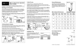
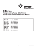
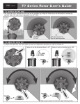
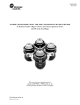
Mini 8, Gear Driven Sprinkler
User’s Guide
The Mini 8 rotor is designed for residential and light commercial
installations. It comes in three sizes, 4" pop up, 6" pop up and 12" pop up.
Nozzling Up The System
To Set The Arc
Screen Maintenance
The Mini 8 rotor arc is pre-set at the factory.
The screen can be accessed through the
bottom of the riser. Remove the cap of the
Mini 8 and lift the riser assembly out of the
housing cannister. If plugged, the screen can
be removed, cleaned, and re-inserted into
the riser.
The Mini 8 rotor has a fixed LEFT stop. To find the left stop position,
rotate the nozzle turret clockwise (to the right) until it stops, then rotate the
nozzle turret all the way back to the left.
To increase the arc, insert the key into the arc adjuster shown in Figure 6.
Hold the turret in place while turning the tool clockwise. Keep turning until
the arc indicator arrow points to the desired arc angle.
The 1.5 GPM nozzle comes pre-installed from the factory. A nozzle tree
consisting of four additional nozzles is provided with each rotor (Figure 1).
Please see the nozzle performance chart for flow rates. By using various
combinations of nozzle flow rates, you can balance the sprinklers to
achieve approximately the same precipitation rates.
As an example indicated in Figure 7, the arc is set to 270˚. The sprinkler
will then water from the left stop and rotate clockwise (see Figure 8) until
270˚, the adjusted right stop, is reached. The sprinkler will then return back
to the left stop and repeat the cycle.
Every case of Mini 8 product contains two Mini 8 rotor keys. The Mini 8 key
is used to pull up the riser, to remove the nozzle, to reduce the radius and
to adjust the arc (Figure 2).
To decrease the arc, insert the key into the arc adjuster. Hold the turret in
place while turning the tool counter clockwise. Keep turning until the arrow
points to the desired arc.
Figure 1
Figure 2
2.0
2.0 GPM
.75
3.0
3.0
PM
G
G
PM
5
.7
Pull-Up
Keyhole
Radius Adjustment/
Nozzle Retention
Screw
1.0
1.5
Arc Adjuster
1.5
G
PM
PM
G
1.0
Nozzle Tree
Arc Angle
Indicator
Mini 8
Rotor Key
To adjust the arc while the rotor is running, turn the turret gently in the
direction that it is spraying. Once the left stop has been located, follow the
directions above to increase or decrease the arc.
To line up the left stop with landscape features which define the left side of
the irrigated arc, simply turn the housing cannister and point the left stop
towards the desired direction. You may also pull the riser up with the key
and rotate the LOWER portion of the riser until the left stop is at the
desired position. DO NOT rotate the TOP portion of the riser.
Figure 6
To Extract/Insert A Nozzle
Increase
Use the winged portion of the key to pull the riser up in order to access the
nozzle orifice. Insert the key into the pull-up hole (Figure 3), turn it 90˚, and
pull up. Hold the riser in the pulled up position.
Decrease
Figure 7
Figure 8
Left Stop Position
Angle Indicator
Points To 270˚
Left Stop
Position
Adjustable
Right Stop
Position
(270˚)
Using the end of the key, turn the radius adjustment screw
counterclockwise until it clears the top of the nozzle. See Figure 4A.
Insert the key into the nozzle right side slot with the pointed end of the key
facing upwards. Use the point to extract the nozzle out. See Figure 4B.
To install a nozzle, press the nozzle into the nozzle socket (Figure 5A).
Turn the radius adjustment screw clockwise to its desired location ensuring
that it is in a position to hold the nozzle in place even if radius reduction is
not required (Figure 5B).
Figure 3
Figure 4
A
Figure 5
B
A
B
Screen
Mini 8 Nozzle Performance
Nozzle Pressure
(Gallons)
(PSI)
Flow
(GPM)
Radius
(Feet)
Pressure
(kPa)
Flow
(L/M)
Flow
(M3/H)
Radius
(Meters)
0.75
30
40
50
0.8
0.9
1.2
19
20
21
207
276
345
3.03
3.41
4.54
0.2
0.2
0.3
5.8
6.1
6.4
1.0
30
40
50
1.1
1.3
1.5
22
23
24
207
276
345
4.16
4.92
5.68
0.2
0.3
0.3
6.7
7.0
7.3
1.5
30
40
50
1.2
1.4
1.6
26
28
30
207
276
345
4.54
5.30
6.06
0.3
0.3
0.4
7.9
8.5
9.1
2.0
30
40
50
1.4
1.7
2.0
30
31
32
207
276
345
5.30
6.43
7.57
0.3
0.4
0.5
9.1
9.4
9.8
3.0
30
40
50
2.3
2.6
3.0
33
34
35
207
276
345
8.71
9.84
11.36
0.5
0.6
0.7
10.1
10.4
10.7
For Product Inquiries:
Installation Tips
CAUTION: The Mini 8 rotor is designed for use in clean-water irrigation
systems only. Sprinkler component damage or malfunction can occur
if operated with any other water source.
The Mini 8 rotor should be installed with
the cap at the finished grade. It is not
designed to be installed below grade.
See Figure 9.
Figure 9
The Toro Company
5825 Jasmine Street
Riverside, CA 92502-0489
Tel: (909) 688-9221
(800) 664-4740
12" Pop Up
6" Pop Up
Figure 9
4" Pop Up
The radius adjustment screw can be used
to reduce the radius throw by up to 25%.
You should note that this does not reduce
the flow of the nozzle.
© 2003 The Toro Company
Form Number 373-0274 Rev. A