1
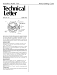
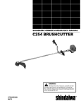
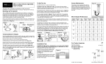
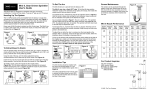
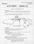
Service
Manual for
Stepping Motor
Quartz (S.M.Q.)
Series 242
Table of Contents
Page
Introduction to the Basic Electronic Function
of Bulova Accutron Quartz Series 242
BASIC ELECTRONIC FUNCTION OF
ACCUTRON QUARTZ SERIES 242
Refer to Fig_ 1
2
Technical Data
3
Tools and Equipment.
3
Crown Positions
4
Power Cell
4
Checking the Frequency (Rate)
4
Setting Instructions and Synchronizing Electronic
ACCUSET® Circuit.
4
Using the ACCUSET Corrector
5
Servicing
'
5
Cleaning and Lubrication
5
Lubricants
5
Mechanical Check Points
5
Electrical Check Points
5
ACCUSET Contact Check
5
Second Hand
5
Basic Test Procedure for S.M.Q. Series 242
6-7
Checking the Components
8
Removing the Components
8
Electronic Circuit
8
Resonator (Quartz) Cannister with Nest
8
Stepping Motor
8
Model 2426.10
8
Setting Instructions
8
Parts Assembly Sequence for Series 242. . . . . . .. 8-9
Parts List for Model 2421.10
9
Parts List for Model 2422.10
10
Parts List for Model 2423.10
10
Parts List for Model 2426.10
10
Illustrated Parts List
11
Notes
10-11
The Accutron Quartz Series 242 is powered by a 1.55
volt "Bulova 242" battery. Voltage from the battery is
introduced into the electronic circuit, which then
transmits current to the Quartz Crystal circuit causing
it to vibrate at 32,768 Hz (cycles per second). The
accuracy of the watch is dependent on the frequency of
the Quartz Crystal. If the Quartz frequency is incorrect,
the TRIMMER capacitor regulator, within the movement,
can be turned to make adjustments of up to 8 seconds
per day.
This Quartz frequency (rate) must then be converted
to one-second impulses before it can be used to
mechanically drive the hands of the watch. This is
accomplished
by means of an electronic divider circuit.
The divider circuit, which contains 15 stages, receives
the signal generated by the Quartz Crystal and divides
this signal by two in each of the 15 stages.
The 15th stage emits one pulse per second. The
divider circuit divides the 32,768 Hz to 1 Hz
(215 32,768), which drives the stepping motor in the
timekeeping mode. The motor in turn drives the gear
train which is connected to the 'dial train causing the
hands to turn.
=
ACCUSET® Operation
In addition to the 15 stage divider, and other
circuits, there are also two independent counter
ACCUSET control logic circuits. These logic circuits
V
perform the resetting function for the ACCUSET
feature. Both are set to zero when the crown is out
(see Fig. 5, Pg. 4, Position 3) and the ACCUSET button
is pushed and released. When the stem is pushed in
(Position 1 or 2) both circuits start to count continuously, one count per second up to 60, and then start
over again.
At a later date, if the sweep hand indicates a timekeeping error, within 30 seconds, pushing the ACCUSET
button wi II correct the error. It wi II cause the motor (and
therefore the hands) to stop
or double pulse in relation to
the error. This is the means
by which a timekeeping error
can be corrected. More
detailed instructions
are
found on Pages 4 and 5.
QUARTZ
CRYSTAL
This illustration
is a simplified
version of the complicated circuit
within the Accutron Quartz Series
242, It is not intended to be used as
a means of conveying any other
thought but a practical way of
demonstrating
basic theory.
TRIMMER
(REGULATOR)
2
Fig. 1
8
ACCUSET
CROWN
1
-I
Technical Data
Tools and Equipment
Bulova Accutron Meter No. 700
Bulova Accutron Quartz Series 242-Electronic
f"'\ovement with quartz resonator, stepping motor
Id ACCUSET
Bulova S.M.a. Meter Accessory No. 9920/6603
<,
"---NO.
BULOVA
700METER
Fig. 2
Diameter
26 mm.-111f2 ligne
Thickness
4.55 mm-Caliber
2421.10
5.50 mm-Calibers
2422.10, 2423.10, 2426.10
Quartz Frequency
32,768 Hz (Cycles per second)
Electronic Circuit
C-MOS Integrated Circuit-one
second signal
increments
Stepping Motor
Bipolar, 12 steps per revolution
.Jwer Cell
One Silver Oxide Battery, 1.55 V., "Bulova 242"
Fig. 3
Note: photographs of units
are not to actual size.
Power Consumption
Max. 7.5 Microamperes (Normal Running)
Max. 3.0 Microamperes (Disconnect Position 3)
Disconnect System
When the stem is pulled out as far as it will go (Position
3), the motor and hands stop, but the Resonator
(Quartz) continues to vibrate, without affecting the
synchronization of the electronic ACCUSET circuit.
ACCUSET
A device that corrects the second hand by merely
depressing a push button. The second hand is reset
automatically to the time standard.
Displays
Model 2421.10-Hour, Minute and Sweep Second
Model 2422.10-Hour, Minute, Sweep Second and Date
Model 2423.10-Hour, Minute, Sweep Second, Date
and Day
Model 2426.10-Hour, Minute, Sweep Second, Date
and Time Zone Feature
Day Indicator
In two languages: English and Spanish, or English and
0rench
BLACK
Driving Wheel Removing Tool: PRESTO#3 for 5 Spoke Wheel
Fig. 4
NOTE: THE CALIBER NUMBER IS ENGRAVED INSIDE
THE BATTERY WELL.
Frequency Counter
With 32,768 Hz capacity
3
Crown Positions
Checking the Frequency (Rate)
Position 1
Quartz Frequency is 32,768 Hz. Rate should be within
± 0.17 seconds per day.
• Normal Running
Position 2
• Instant Calendar Setting
• Hour Hand Adjustment for Time Zone Feature (Model
2426.10)
Position 3
• Stops Second Hand
• Synchronizing ACCUSET circuit
• Minute and Hour Hand Setting
• Disconnect Position: Conserves life of power cell
when watch is not in use
Adjusting the Frequency (Rate)
Use a screwdriver to turn the trimmer in the appropriate direction (+ or -) (See Fig. 1, Pg. 2). The
maximum rate change is approximately 8 seconds
per day.
Setting Instructions and Synchronizing
Electronic ACCUSET Circuit
Important: It is necessary to re-synchronize
ACCUSET circuit after:
A. Installing a Power Cell.
B. Servicing the Movement.
C. Interruption of Current (e.g. loose contact screw).
Setting Instructions
Step 1. When sweep second hand of the watch
reaches the 60th second mark (12 o'clock marker),
pull crown out to Position 3 (See Fig. 5,).(Allhands
will now stop.)
Step 2. Press and release ACCUSET button.
(ACCUSET circuit is now synchronized with position
of second hand.)
Step 3. Turn hands forward until date changes. (This
establishes midnight.) .
Fig. 5
Power Cell
Insert Power Cell with printed (+) side up.
Recommended Power Cell: "Bulova 242" (1.55 volt)
Step 4. If A.M., advance hands 5 minutes ahead of a
time standard being used. Then gently turn the
minute hand back to correct time.
If P.M., advance the hands past 12 o'clock (noon)
to 5 minutes ahead of time standard and then gently
turn the minute hand back to correct time.
Step 5. When time standard being used reaches the
60th second mark (12 o'clock marker), push crown to
the "intermediate" position (Position 2). All hands
will start instantly.
Step 6. First set the date, then the day. Crown must
remain in Po'sition 2. Slowly turn crown forward to
correct date; backward to correct day. Push crown
"in" (Position 1).
Note: Day Indicator is printed in English and
Spanish, or English and French. Set accordingly.
Calendar cannot be set manually between 9:00
P.M. and 1:00 A.M. However, the mechanism will not
be damaged if crown is accidentally turned during
this period of time.
Note: The caliber number
is engraved inside the battery well.
Fig. 6
4
Additional Setting Information
Once the ACCUSET circuit has been set (Refer to
Step 1 and Step 2), there is no need to reset it,
unless the power cell has been removed, or there
has been an interruption of current.
Using the ACCUSET Corrector
After a period of time, if the watch is no longer
accurate to the exact second, press and release the
ACCUSET button the instant the time stenderd used
naches
the 60th second (12 o'clock) marker. (Maxium correction
is + or - 30 seconds.) The sweep
second hand of the watch will temporarily
stop if it is
fast, or accelerate if it is slow until it is in synchronization with the time standard.
Important: When the crown is "all the way out"
(Position 3), motor and all hands stop. The ACCUSET
circuit continues to operate and the quartz crystal
continues to vibrate, using extremely little current.
Store watches with crown in "out" (Position 3) to
prolong battery life.
, MOTOR
LEADS
\~
PEEP-HOLE FOR
INSPECTING THE
Setting and Calendar Mechanisms-use
thick oil
such as "Moebius 9024".
Calendar Jumper Springs contacting
plastic-use
light grease such as "KT 22".
Check the Following
Mechanical
Points:
• Hand adjustment:
hands level, not touching dial
markers, etc.
• Driving wheel correctly fitted on the third wheel
pivot
• Functioning
of the calendar mechanism
• Functioning
of the hand setting mechanism
• Stop lever should not touch the intermediate
train wheel when setting stem is in the "intermediate" (Position 2) or pushed "in" (Position 1).
• Freedom
of the train wheels:
To check train freedom, remove power cell,
electronic
circuit, driving wheel and motor. Reinstall
driving wheel.
CELL STRAP
DISCONNECT/
SYSTEM
ACCUSET
CONTACT
Lubricants:
With the stem in the "in" position, direct a stream
of air from a watchmaker's
hand blower horizontally
against the driving wheel. The train wheels will turn if
they are free. If not free, recheck for train blockage,
excessive tension of center second spring, calendar
mechanism
blockage, etc.
CELL CONTACT
SPRING INSULATOR
Fig. 7
Servicing
Note: For disassembly
and reassembly sequence,
see pages 8 and 9. Circled numbers refer to the
assembly sequence of various parts.
The following components
should not be dipped in
solvent:
• Dial Support (#10.106)
• Electronic Circuit (#10.513)
• Calendar Mechanism
Maintaining
Plate (#13.101)
• Stepping Motor (#20.510)
• Resonator (Quartz Cannister with Nest) (#40.510)
• Date Indicator (#91.440)
• Day Indicator (#91.441)
• Casing Ring (#93.010)
Note: Electronic Unit Support Bridge (#10.580) and
the Battery Support (#20.701) may be left in the
movement.
Check the FOllowing Electrical
Points:
• Screws of electronic
circuit are tight
• Contact spring screw is fitted with its insulator
(Part #20.652)
• Printed circuits are clean (use leather buff, no
abrasives)
• Contact of the disconnect
system as follows:
Sight through view-hole (Fig. 7, Pg. 5). Make sure
contact spring presses on setting lever contact stud
when the hand setting crown is pulled "out" as far
as it will go (Position 3).
Check ACCUSET Contact As Follows:
• Contact spring should touch the main plate when
ACCUSET button is pressed with movement in the
case.
• Contact spring should not touch the main plate,
and should clear the plate by at least 0.10 mm. when
the ACCUSET button is released.
Second Hand
Cleaning and Lubrication
~~fter
removing the components
listed above, clean
movement using "One-Step",
"Miracle Plastic" or
equivalent solution. Never oil train wheels with con-,
ventional watch oil. If cleaned in conventional
manner, do not oil train wheels but lubricate the dial
train, setting and calendar mechanism as shown on
pages 8 and 9, using the lubricants
listed.
The second hand is counterpoised.
If replacement
is necessary, use only genuine replacements.
When redialing, wait until motor has indexed a few
times,then
pull crown to the "out" position (Position
3). While holding in position, align the sweep hand
with the 12 o'clock marker, and press into place.
(Servicing information
continued on page 8.)
5
Basic Test Procedure for S.M.Q. Series 242
Step 1
1.50 to 1.58 Volts: O.K. to Use.
Proceed to Step'
Check Power Cell
/'
Less than 1.50 Volts: Replace.
Step 2
u
Rate O.K. or regulate if
necessary. Proceed to Step 3...
Check Frequency (Rate)
,
No Rate or Very Erratic ...
Replace Electron!
,
Step 3
Connect Meter to
Service Accessory
--r"
Remove Power Cell from
Movement and place in Meter
Cell Well. Set Meter Selector
at "LOW AMPLITUDE". Set
watch to 11:45 P.M. to engage
calendar mechanism. Push
crown "in" (Position 1).
First, Connect Bit
loop on Service Pmarked "Blue"; Y
Clip to loop mark
Then, Connect
ment Clip to Cell
Connect "Black"
Clip to Cell Conte
(Lower). Disregan
meter reading. (S
If Motor turns-d
tension. Proceed
Step 4
Carefully lift Center Second
Tension Spring.
Motor Check
If Motor still does
hesitates- remoi
'+--
Step 5
Current Check
6
With Meter still at "LOW
AMPLITUDE", remove Black Clip
from Lower Contact Spring and
touch it to the bare area of one
of the Motor leads (close to the
screw). See Fig. 7 Pg. 5. Motor
gear should index one tooth.
If removed in Step 4, return
Black Clip to Lower Contact
Spring. Set Meter Selector to
"READ MICROAMPERES."
Pointer will fluctuate. This is
normal.
NOTE: CHECK ACCUSET FUNCTION AS DESCRIBED ON PAGES 4 AND 5.
Lift the clip from
allow 2 seconds
to "recover," ant
other Motor lead.
should again ind
Continue alterna
from one Motor I
at 2 second inter
If maximum read"
microampe
, ci
If maximum read
microamperes ...
Note: It is imperative that the basic :'st~p.by:step"
procedure be strictly adhered to begmnmg with
Step 1 and continuing through Step 5.
Rate O.K. or regulate if necessary.~
,.
Proceed to Step 3.
IC
Circuit
Board.
ue Meter Clip to
.ttachrnent
ellow Meter
ed "Yellow."
Red AttachStrap (Upper).
Attachment
rct Spring
j fluctuating
ee Page 3).
If Rate is still not correct,
L
r-_~I
'-
replace Quartz Crystal. (Return
original circuit board to your
stock).
V
1I
Motor turns without
'------'
~-...
II
hesitation.
Motor still does not turn, or it
hesitates...
Circuit and Motor O.K.
Proceed to Step 5...
I-_ •..•
••
~
Continue to Step 4...
'"-..
''-------'
~
_
-
J
)
~
~~-----------------------------------------I
\
ecrease spring
to Step 5 ...
not turn, or it
,e Driving Wheel. .~ __ ~
If Motor turns ...
Remove blockage from train or
calendar mechanism.
If Motor does not turn, or it
hesitates ...
Continue
as follows ...
If Motor indexes 12 times
(1 complete rotation) Motor is
O.K. and Circuit is faulty.
Replace Circuit.
Motor lead,
for accessory
I place it on the
, Motor gear
ex one tooth.
ting Black Clip
ead to the other
vals.
Proceed to Step 5 ...
If Motor does not index, or it
hesitates, Motor is faulty.
Replace Motor.
ing is below 7.5
ircr/"\s O.K.
r
:i"9 is above 7.5)
••
Replace Electronic
Circuit.
~
If circuit does not correct-return
it to stock and replace Motor .
7
r--------------------------------------------------------------~--------------------------------~
(Servicing
information
continued
from page 5.)
Model 2423.10
Checking the Components
Note: The following
components
can be tested and
replaced, if necessary, without removing the movement from the case (See Pages 6 and 7 for basic test
procedures):
1.
2.
3.
first)
Power Cell (#20.570)
Electronic Circuit (#10.513)
Stepping Motor (#20.510) (remove driving
(#30.051)
4. Resonator
(Quartz Crystal)
Circled figures refer to the assembly sequence of
the various parts.
Fig. 8
DIAL UP
wheel
(#40.510)
Removing the Components
Electronic Circuit
Grip circuit board near the trimmer.
or scratch the printed circuit.
Do not touch
Resonator (Quartz) Cannister with Nest
33.102-----=..-L--'
k------------
53.201
13.101
@
When disassembling,
remove the Cannister and its
nest as a single unit. Do not pry up by the printed
circuit leads.
Note: Some movements do not require a Quartz
Cannister Nest.
------91.440
@
Stepping Motor
When removing, use the flange of the motor
housing to apply presure. Avoid pulling or pushing
on the motor gear. Care should be taken that the
printed circuit leads are not damaged.
@
31.046
----c;:
>-------51.090.01
~---51.090
36.051-~
@
@
33.014
MODEL 2426.10
This model is similar to Model 2422.10 with the
additional
feature that the position of the hour hand
can be changed from one time zone to another without affecting the other hands.
';,------31.102
~~.
(j)
@
,. ~36.052
-.....;..,'~®
31.083
®
~
\
Instructions
for setting this model are basically the
same as the Setting Instructions
shown on Page 4,
except for the setting of the time zone feature.
51.052
®
~.L~®
1. To Change to Another Time Zone: Pull crown out
to "intermediate"
(Position 2). Each slight turn
forward or backward will change the hour in one hour
increments without disturbing the minutes, seconds or
date.
8
®
~WJO
Setting Instructions
2. To Set the Date: Pull crown out to "intermediate"
(Position 2). The date can be advanced or moved
back by turning the crown rapidly. (Be sure that
the time is set in the correct 12 hour period so
that the date will change at midnight and not at
noon.)
«:'::--31.100
~~r-------~
'~31.124
CD
31.041
®
Lubricants
Moebius
c-- KT22
9024
Parts List for Model 2421.10
PART
NUMBER
10.020
10.048
10.048.01
10.106
r>;
DIAL DOWN
10.106-1
10.106-2
10.106-3
10.513
10.513.01
10.513.02
10.048.01
10.580
10.580.01
20.510
20.510.01
20.570
20.652
20.701
20.701.01
40.700
®
60.131
®
~20.652
~
20.701.01
(j
"'" 10.048.01
10.048
")
~
f
0
®
30.025
30.081
®
30.012
20.510
CD
®
20.761
20.761.02
20.701.02
20.761
20.763
30.012
30.025.08
30.051
30.081
31.041
31.046
31.083
31.100
31.102
31.124
40.510
40.700
51.020
51.052
51.080
51.090
51.090.01
56.070
60.131
61.101
61.101.01
61.241
90.000.01
93.010
20.570
@
93.010-1
93.010-2
93.010-3
PART NAME
Main Plate
Train Wheel Bridge
Train Wheel Bridge Screw
Dial Supports
Diameter
Height
.40
26.85
.40
28.35
.40
30.35
Electronic Circuit
Electronic Circuit Screw
Electronic Circuit Ground Screw
(Use 10.048.01)
Electronic Unit Support Bridge
Electronic Unit Support Bridge Screw
Stepping Motor
Stepping Motor Screw
Power Cell
Insulator for Contact Spring
Battery Support
Battery Support and Contact
Spring Screw (Use 10.513.01)
Battery Support and Cell Strap Screw
Power Cell-Strap
Contact Spring
Intermediate
Double Wheel
Third Pinion
Drive Wheel over 3rd Pinion
Sweep Second Pinion Height 5.80
Minute Wheel
Hour Wheel Heights 1.71 or 1.42
Cannon Pinion with Driver
Heights 2.35 or 2.60
Set Wheel
Motion Work Set Wheel
Hand Set Pinion
Resonator (Quartz)*
Resonator Cannister Retaining Clamp
Hand Set Stem
Rocking Bar
Set Lever with Axle
Set Lever Bridge (Jumper)
Set Lever Bridge Screws
Stop Lever
Second Pinion Friction Spring
Rocking Bar Spring
Rocking Bar Spring Screw
Hour Wheel Friction Spring
Use Dial Washer 7 AK #86-3
Dial Screws
Casing Ring
Diameter
Height
26.90
2.50
28.40
2.95
30.40
2.95
63/64 Minute & Hour Hands
65C Sweep Second Hand
*Note: Some Resonators
BASIC
MODEL
2421.10
2423.10
2423.10
2421.10
2421.10
2421.10
2423.10
2423.10
2423.10
2423.10
2423.10
2423.10
242
2423.10
2423.10
2423.10
2423.10
2423.10
2423.10
2423.10
2423.10
2423.10
2421.10
2423.10
2421.10
2423.10
2423.10
2423.10
2423.10
2423.10
2423.10
2421.10
2423.10
2423.10
2423.10
2423.10
2423.10
2423.10
2423.10
2423.10
2423.10
2423.10
2423.10
2423.10
2423.10
do not require a nest.
9
Parts List for Model 2422.10
Varying From or Addition To Model 2421.10
PART
NUMBER
10.020
10.106
10.106-1
10.106-2
10.106-3
13.<101
13.101.01
30.081
31.046
31.083
33.014
33.028
51.052
91.440
PART NAME
Main Plate
Dial Supports
Diameter
Height
26.85
1.35
28.35
1.35
30.25
1.35
Calendar Mechanism
Maintaining
Plate
Calendar Mechanism
Maintaining
Plate Screw
Sweep Second Pinion Height 6.75
Hour Wheel Heights 2.12 or 2.37
Cannon Pinion with Driver
Heights 3.30 or 3.55
Intermediate
Calendar Wheel
Calendar Driving Wheel
Rocking Bar
Date Indicator
BASIC
PART
MODEL
NUMBER
2422.10
10.020
10.106
2423.10
2423.10
2423.10
2423.10
2423.10
10.106-1
10.106-2
10.106-3
13.101
13.101.01
2423.10
2423.10
30.081
31.046
31.048
2423.10
2423.10
2423.10
2423.10
2423.10
Parts List for Model 2423.10
Varying From or Addition To Model 2421.10
PART
NUMBER
10.020
10.106
10.106-1
10.106-2
10.106-3
13.101
13.101.01
30.081
31.046
31.083
33.014
33.028
33.102
36.051
36.052
51.052
53.201
91.440
91.441
PART NAME
Main Plate
Dial Support
Height
Diameter
26.85
1.35
28.35
1.35
30.25
1.35
Calendar Mechanism
Maintaining
Plate
Calendar Mechanism
Maintaining
Plate
Screw
Sweep Second Pinion Height 6.75
Hour Wheel Heights 2.12 or 2.37
Cannon Pinion with Driver
Heights 3.30 or 3.55
Intermediate
Calendar Wheel
Calendar Driving Wheel
Pinion of Day Corrector
Corrector Setting Wheel (Day)
Corrector Intermediate
Setting Wheel
(Day)
Rocking Bar
Day Corrector
Date Indicator
Day Indicator
Parts List for Model 2426.10
Varying From or Addition To Model 2421.10
31.083
33.014
33.028
36.030
36.051
36.052
36.100
91.440
PART NAME
Main Plate
Dial Support
Diameter
Height
26.85
1.35
28.35
1.35
30.25
1.35
Calendar Mechanism
Maintaining
Plate
Calendar Mechanism
Maintaining
Plate
Screw
Sweep Second Pinion Height 6.75
Hour Wheel with Spring
Hour Wheel with Star
Heights 1.70 or 1.95
Cannon Pinion with Driver
Heights 3.30 or 3.55
Intermediate
Calendar Wheel
Calendar Driving Wheel
Corrector Wheel (Hour)
Corrector Setting Wheel (Zone)
Corrector Intermediate
Setting Wheel
(Zone)
Corrector Driver (Hour)
Date Indicator
BASIC
MODEL
2426."
2423.10
2423.10
2423.10
2426.10
~423.10
2423.10
2426.10
2426.10
2423.10
2426.10
2426.10
2426.10
2423.10
2423.10
2426.10
2423.10
BASIC
MODEL
2423.10
Note: Parts for 2426.10 listed above are not
illustrated.
2423.10
2423.10
2423.10
2423.10
2423.10
2423.10
2423.10
2423.10
2423.10
2423.10
2423.10
2423.10
2423.10
2423.10
2423.10
2423.10
2423.10
Notes
Calendar Mechanism: Turn hands clockwise until
DATE changes (disregard Day Indicator). Push Crown
"in" (Position 1). Assemble Minute and Hour Hands at
the 12 o'clock position.
Second Hand: When
indexed a few times,
position (Position 3).
the sweep hand with
into place.
redialing, wait until motor has
then pull crown to the "out"
While holding in position, align
the 12 o'clock marker, and press
Caution: Do not remove the "C" shaped clamp (Date
Corrector) from the Rocking Bar Assembly (#51.052).
/
10
10.020
10.048
10.106
10.513
20.652
20.701
b
@
§
31.041
31.046
31.083
I)
40.510
T
10.048.01
10.513.02
20.763
20.761
31.100
'\)
~
31.102
31.124
13.101
+
IP
0
20.570
10.580
30.012
30.025
33.014
33.028
T
10.513.01
20.701.01
51.020
51.052
I
10.580.01
51.080
51.090
53.201
i
30.051
33.102
~
40.700
20.510
56.070
60.131
30.081
(>
o
36.051
36.052
~
61.101
T
T
l
T
T
13.101.01
20.510.01
51.090.01
61.101.01
90.000.D1
I
20.701.02
Fig. 9
11
BULOVA WATCH COMPANY, INC.
TECHNICAL INFORMATION SERVICES
75·20 Astoria Blvd.
Jackson Heights, New York 11370
(212) DE 5·6000
PATENT NOTICE
The ACCUTRONII Quartz Series 242 timepiece is manufactured by
Bulova Watch Company, Inc., under issued patents as well as pending
applications.
"Accutron", "Bulova", "Accuset", and "'!.l" are registered trademarks
of the Bulova Watch Company, Inc.
All Information contained in this booklet is based on the latest
product information available at the time of printing. The right is
reserved to make changes any time without notice.
1978 Bulova Watch Company, Inc. All Rights Reserved.
[[)
7178
PRINTED IN U.S.A.