1
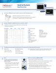
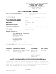
G
E
C
B
F
A
H
D
Please Read Carefully
Prior to Installation
• Use caution and always wear eye protection.
• Avoid skin contact with fuels and oils.
• If you don’t feel confident installing this product, please seek professional assistance.
Legal Notice!
Installation of this kit is intended for closed circuit competition puposes only. Modifying any portion of a motor vehicles
emmissions system can be in direct violation of state, local or federal laws. Please consult your local authorities for
more detailed information regarding specific vehicle modification and equipment laws in your area. The purchaser of
this performance kit acknowleges that it is not intended for street use.
What’s Included in your kit
A)
B)
C)
D)
2 x PowerCell Blockoff plates
1 x SAS Shunt Plug
1 x Evap Solinoid Shunt
1 x Manifold Vacuum Plug
E)
F)
G)
H)
1 x Large Airbox Housing Cap
1 x Small Airbox Housing Cap
4 x Small Zip-Ties
4 x Stainless Allen Screws
PowerCell Performance • 10347 Los Alamitos Blvd • Los Alamitos Ca 90720 • 800.321.1927 www.powercellperformance.com
Installation Instructions
Remove Gas Tank -
Follow the directions provided in the factory service manual to
properly remove the gas tank, exposing the airbox and the frame.
You will also need to remove the 2 air intake ducts so that
removing and installing the lower airbox housing will be much
easier.
Remove the Air Box Cover -
Unplug the Air Temperature Sensor and remove the 2 Torx
screws securing the Crank Case Vent tube on top of the
airbox. Now remove the 8 Torx head screws around the
perimeter of the box securing the lid in place. Remove the
cover exposing the factory Velocity Stacks, and set it aside
for later re-installation.
Remove the Airbox -
Using an 8mm socket, remove the factory Velocity
Stacks along with the mounting screws and spacer
sleeves.
Remove the lower Airbox by carefully liftng if off the
throttle bodies, exposing the SAS control valve and
it’s plumbing attached underneath. You will need to
remove the SAS control valve from it’s bracket underneath the airbox. You can do so by simply pulling
down on it’s rubber mount, separating it from the factory braket, and disconnecting the larger hose connected to the underside of the airbox. At this time we
recommend removing the SAS valve bracket as well,
making it easier to service your bike in the future.
PowerCell Performance • 10347 Los Alamitos Blvd • Los Alamitos Ca 90720 • 800.321.1927 www.powercellperformance.com
Installation Instructions
Thoughts on Water Control -
If you’re running an air-filter in the stock filter
location, we recommend removing the small
drain hose from underneath the airbox and
replacing it with the provided small rubber cap.
Secure the cap with the small Zip-Tie and set the
drain hose aside, we will not be using it again.
If you’re running a PowerCell Pod Filter System,
we recommend removing the drain hose from the
airbox, but leaving the small nipple underneath
the airbox open so any water that enters the
airbox can quickly drain.
In either case, install the large nipple cover over
the open SAS port underneith the airbox and
secure it with a provided Zip-Tie.
Removing the SAS System -
You can now remove the 4 bolts holding the SAS
system to each cylinder head with an 8mm socket.
After you’ve done so, disconnect the SAS control
solinoid from the wiring harness by lifting the small
tab on the harness side. At this point, the entire SAS
system should be free to be removed from the bike
as a complete unit. Set it aside in a safe place should
you ever need to re-install it.
Install the Cylinder Head Block-Off Plates -
Using the provided 4 stainless steel Allen screws,
install the cyclinder head block-off plates. There is
no need to use any form of sealant, the factory reed
valves that we left intack in the cylinder heads will
seal against the new block-off plates.
PowerCell Performance • 10347 Los Alamitos Blvd • Los Alamitos Ca 90720 • 800.321.1927 www.powercellperformance.com
Installation Instructions
Install the SAS Control Solinoid Shunt -
Locate the yellowish colored shunt provided in your kit
and install in into the vacant connector that originally
connected to the SAS control solinoid. Use one of the
provided Zip-Ties to secure the shunted connector to the
wiring harness as shown.
Remove the Evaporation Recovery Canister -
The Evaporation Recovery System serves to capture any
fuel vapors that may escape from the fuel tank while not in
use. These vapors are stored in the small canister, and
re-entered into the intake system once the engine is
running and warm.
Locate the Evap Cannister under the seat in the tail
section of the bike. Snap the cannister out of its cradel and
remove the 2 attached hoses. Now remove and set aside
the cradle itself, re-attaching the 2 mounting screws.
Removing the Evap Control Solinoid -
Looking at the 2 hoses you just disconnected from the
cannister, follow the smallerhose forward along the frame
rails until it ends, connected to the Evap System
control Solinoid. Using an 8mm socket, remove the solinoid
retaining clamp from the frame. Now disconnect the
solinoid from the wiring harness by separating the 2 tabs on
the harness side and pulling the connector off. Pull the
hose leading to the tail section of the bike through the frame
rails so that the whole system can be removed.
Now follow the other hose on the solinoid down between the
two throttle bodies. You need to cut this hose and plug it
with the provided aluminum plug, tucking it out of the way
when done (see picture).
PowerCell Performance • 10347 Los Alamitos Blvd • Los Alamitos Ca 90720 • 800.321.1927 www.powercellperformance.com
Installation Instructions
Install the EVAC Control Solinoid Shunt -
Locate the black colored shunt provided in your kit and
install in into the vacant connector that originally
connected to the EVAC control solinoid. Use one of the
provided Zip-Ties to secure the shunted connector to the
wiring harness as shown.
Securing the Shunted Connectors -
Before you begin reassembly, ensure that the SAS and
EVAC harness connectors are securely tucked away and
secured to the main wiring harness (as shown to the right).
Snip the excess Zip-Tie for a clean installation.
Re-Routing the Fuel Tank Breather -
The remaing small hose that was attached to the
canister runs directly back up to the fuel tank, and
connects to the fitting on the throttle side of the
filler neck. You can now pull this hose back
through the bike and re-route it so it runs down
the left side of the engine along with the radiator
over-flow hose. Once re-routed, cut the excess
hose off so it will drain just in fornt of the stator
cover.
PowerCell Performance • 10347 Los Alamitos Blvd • Los Alamitos Ca 90720 • 800.321.1927 www.powercellperformance.com
Installation Instructions
Re-Installing the Airbox -
Re-install the Airbox base and cover reversing the steps
used during disassembly. Use caution not to lose the small
o-ring that sits on top of the cover and seals the Crankcase
Vent. Connect the Air Temperature Sensor connector and
position the cable into it’s retainer.
Install the Fuel Tank -
Install the Fuel Tank as noted on page
65 of the factory service manual.
Enjoy Your New PowerCell Performance SAS Removal Kit!
PowerCell Performance • 10347 Los Alamitos Blvd • Los Alamitos Ca 90720 • 800.321.1927 www.powercellperformance.com