1
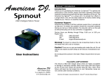
KTD-405/405A Keypad
User Guide
Introduction
Welcome to the KTD-405/405A User Guide. This guide helps operators use the
KTD-405/405A controller keypads to control cameras, digital recorders, matrixes,
and multiplexers.
• Keypad operation is affected by the type of system installation. See pages 2 - 3
for information about Digiplex and Zone installations.
• Commonly used device commands are described on pages 4 - 9.
TIP
You’ll find special items such as Tips and
Cautions in the page margins. These
items make setup and basic operation
easier.
• For basic keypad descriptions and operations, see pages 10 - 12.
• For basic I/O box cable connections, see pages 13 - 14.
• Use page 15 to record your system device/zone numbers and descriptions.
You can find more detailed information about the keypads and other system
devices in their related user manuals.
TIP
If you have a problem configuring or
operating your keypad, try these solutions
in this order:
1) Re-read the User Guide
2) Read the corresponding section of the
appropriate user manual
3) Call Technical Support
KTD-405
From 6 A.M. to 5 P.M. (Pacific time)
If calling from outside the United States:
011-1-541-754-9134
If calling from within the United States:
800-469-1676
From 5 P.M. to 6 A.M. (Pacific time)
541-740-3589
KTD-405A
1
|
Introduction
Information in this document is subject to
change without notice.
© 2003 GE Interlogix. All rights reserved.
Basic Zone Installation / Zone Keypad Mode
If your system uses one or more DVMRe digital video recorders or GE multiplexers as the main
switching devices, then the system is a basic zone installation. A zone installation can have as
many as 32 zones, each zone having one DVMRe or multiplexer that serves from 1 to 32 cameras.
The outputs from the zone’s switching device connect directly to dedicated monitors.
If you have a zone installation, your keypad
defaults to zone mode. If your keypad is in
zone mode, the LCD panel shows zone,
camera, and monitor fields.
LCD display of keypad in zone mode
TIP
LCD display: Compare the LCD display for
zone mode to the LCD display for Digiplex
or hybrid zone mode on page 3.
TIP
System Information: Use page 15 of this
document to record the numbers and
descriptions of the DVMRes and multiplexers in your system.
NOTE
DVMRe: See page 6 to call up a DVMRe
when the keypad is in zone mode.
2
|
Basic Zone Installation / Zone Keypad Mode
Basic Digiplex Installation / Digiplex and Hybrid Zone Keypad Modes
If your system uses one or more GE matrix switchers as the main switching devices, then the
system is a basic Digiplex installation. A Digiplex system can have 512 cameras, one or more
matrix switchers with 64 monitor outputs, up to 32 multiplexers, and up to 32 recorders. In
addition, optional recording devices (DVMRe, DSR, or VCR) can connect to the matrix switcher.
Digiplex systems do not require that the DVMRes have dedicated monitors.
If you have a Digiplex installation, your keypad
defaults to Digiplex mode. If your keypad is in
Digiplex mode, it shows the active camera and
monitor numbers.
LCD display of keypad in Digiplex mode
You can use the keypad to control a DVMRe in
a Digiplex installation (see page 6). In this
case, the keypad is in “hybrid” zone mode. If
your keypad is in hybrid zone mode it shows
zone, camera, and monitor numbers, and the
DVMRe type.
LCD display of keypad in hybrid zone mode
TIP
LCD display: Compare the LCD display for
Digiplex and hybrid modes to the LCD
display for zone mode on page 2.
NOTE
DVMRe: See page 6 to call up a DVMRe
when the keypad starts in Digiplex mode.
3
|
Basic Digiplex Installation / Digiplex and Hybrid Zone Keypad Modes
Programming and Controlling a
CyberDome
Selecting a Monitor
There are two methods for
monitor selection. For
example, to select monitor 1
perform one of the following.
Selecting a camera
•
There are two methods for
camera selection. For example,
to select camera 1 perform
one of the following.
If you have fewer than ten cameras, press 1;
if you have tens of cameras, press 0,1; if you
have hundreds of cameras, press 0,0,1.
• Press 1,
•
•
If you have fewer than ten monitors, press
1; if you have tens of monitors, press 0, 1; if
you have 100 – 128 monitors, press 0, 0, 1.
Press mon, 1,
.
.
Programming presets
Move the camera to the desired position.
• Standard presets: Press store, <preset number>,
store to store presets.
• Autopan limits: Press store,
set autopan limits.
or
, store to
• Quick store: Press store, [aux 1 – 4], store to
store preset positions 58 – 61.
Calling up a preset
To move a CyberDome camera to a preset
position, press find then <preset number>.
Calling up a tour
To initiate on a CyberDome camera a previously programmed tour, press tour then <tour
number>.
4
|
Programming and Controlling a CyberDome / Selecting a Monitor
TIP
Presets:
•
CyberDome cameras can store up to 32
(numbered 00 – 31) or 64 (numbered
00 – 63) preset positions, depending
on the camera model.
• Preset numbers 62 and 63 are reserved
for autopan limit settings.
• If you are going to reprogram a large
number of existing presets, it is
advisable to clear all presets stored in
memory.
Controlling a Matrix Switcher
TIP
Sequence tours: In order to view sequence
tours, your system must include a KTD-440
and you must program the KTD-440 with
one or more sequence routines.
Viewing a camera on a specific monitor
At the default keypad menu, enter the monitor number then the camera number. See page 4 for
camera and monitor number entry methods.
Initiating sequence tours
To initiate a camera sequence, press seq then <sequence routine number 1 - 7>.
Initiating group sequences
1 Press esc + zone.
2 At the prompt, press tour.
3 At the prompt, enter the group sequence number. For single digit numbers, press
<number key>,
. For double digit numbers, press <first digit key>, <second digit key>.
Enable or disable alarm mode for a monitor
Press
. If the alarm mode is enabled, A appears on the affected monitor.
5
|
Controlling a Matrix Switcher
TIP
Group sequences: In order to initiate a
group sequence, you must first program
the sequence at the matrix switcher.
Controlling a DVMRe
Calling up a DVMRe in a Digiplex installation
To select a DVMRe when in Digiplex mode, perform the following.
1 Press zone. The keypad switches to hybrid zone mode.
2 Enter the DVMRe/zone number.
Calling up a DVMRe in a zone installation
To select a DVMRe when in zone mode, perform the
following.
1 Press zone.
NOTE
Installations: See pages 2 - 3 for descriptions of zone and Digiplex installations
and the related keypad modes.
NOTE
System information: You must know the
DVMRe/zone number to call a DVMRe
from the keypad. If you don’t know that
information, contact your system installer,
integrator, or administrator and record
that information on page 15.
2 Enter the zone number.
Calling up multiscreen views on a Triplex or DVMRe (zone or hybrid zone mode only)
• Press view, <number keys 1 to 9>
or
• Press view, 5 repeatedly to step through the available views.
Calling up multiscreen views on other DVMRe models and multiplexers
Press view repeatedly to step through the available views.
6
|
Controlling a DVMRe
TIP
Hybrid Zone mode:
• Press esc to return from hybrid zone
mode to Digiplex mode.
• You do not have PTZ control of cameras
in hybrid Zone mode.
TIP
Error: The keypad beeps when you enter
a zone number if that zone number does
not exist or the keypad is not communicating with the DVMRe.
Searching Recorded Events on a DVMRe
To initiate a search, press
. The Disk
Analysis Screen appears on the monitor. The
default view shows the entire time period
currently saved on the disk.
At the Motion Search menu, select a time
parameter.
At the custom time menu, customize a time
period to search.
Custom time menu
Motion Search menu
• To navigate through the options push up or
down on the joystick, or press esc + or
esc + .
Disk Analysis Screen
• To scroll forward or backward in disk time
push the joystick up or down, or press esc +
or esc + . The black indicator arrows move
left and right to show the selected time.
• To view shorter or longer spans of time, push
the joystick left or right, or press
or
. There are four view levels.
• To view playback of the currently selected
time period, press
.
• To specify search parameters, press
Motion Search menu appears.
7
|
. The
Searching Recorded Events on a DVMRe
• To select an option push left or right on the
joystick, or press esc +
or esc +
. You
can select only one option at a time.
• To initiate a search on a selected preset time
parameter, press
. Playback begins and the
motion search setup screen appears.
• To customize a time period to search, select
Custom and press
. The custom time
menu appears.
• To apply filters to a custom or preset time
parameter, press
. The Search Filters
menu appears.
• To navigate through the date and time
fields, push left or right on the joystick, or
press esc +
or esc +
.
• To change settings for each option press
esc + or esc + .
• To accept the customized time settings press
. Playback begins and the motion search
setup screen appears.
Continued on next page...
TIP
Exiting Search mode: To exit the search
function, continue pressing esc until all
search menus disappear from the monitor.
Searching Recorded Events on a DVMRe, continued
At the Search Filters menu,
select custom search parameters.
At the motion search setup
screen, enable or disable areas
for motion detection.
• To move the selection box
around the screen, use the
joystick.
• To navigate up and down
through the main options in
the left column, push up or
down on the joystick, or
esc + or esc + .
• To select or deselect a box in
the left column, push right
on the joystick or press esc +
. If you select a box, the
right
column for that item
Search Filters menu
becomes editable.
• In the right column, to navigate through the editable options, push
or esc +
. To change
left or right on the joystick, or press esc +
settings push up or down on the joystick, or press esc + or . To
accept settings press
. The left column becomes active.
• To select or deselect cameras, press the number keys. For single digit
camera numbers press <number key>,
. For double digit camera
numbers press <first digit key>, <second digit key>. Press
to toggle
between selecting all cameras or only camera 1.
• To initiate the search, select START SEARCH and press
appropriate Search Results menu appears.
8
|
Searching Recorded Events on a DVMRe, continued
The
Motion search setup screen
• To toggle the selection box
between active and neutral
mode, press . If the box is
in active mode, aDappears
in the box. Move the box
over areas you want to
enable for motion detection.
• To toggle a selected block between disabled and neutral mode,
press . If the selection box is in disabled mode, an U appears in
the box. Move the box over areas you want to disable for motion
detection.
• To start the search, press
appears.
Continued on next page...
. The appropriate Search Results menu
Searching Recorded Events on a DVMRe, continued
At either Search Results menu, select an entry.
Activity, text, motion, and alarm
Search Results menu
• If your search produced no results, press
Time/date Search Results menu
to return to the Search Filters menu.
• To scroll through the results, use the joystick, or press esc +
• To play a selection, press
or esc +
.
.
• During playback, to set an event replay continuously, press seq. “Repeat” appears at the top of
the monitor screen.
• During playback, to return to the Search Results menu, press
• To stop playback, press
9
|
.
Searching Recorded Events on a DVMRe, continued
.
Key Descriptions and Operation
DSR, VCR, DVMRe, or Multiplexer Selection
Press dsr/vcr, <device number> in
Digiplex mode to address a remote
recording device (other than a DVMRe).
Press zone, <zone number> in Zone or
Digiplex mode to select a DVMRe.
DSR, VCR, DVMRe, or Multiplexer Operation
Start record mode.
• Step selected monitor through
programmed multiplexer multiscreen
views. If using a Triplex™ multiplexer,
press view, [1 – 9] to select a view (see
page 6)
• For newer model cameras, hold for 3
seconds to view camera name and
number.
Joystick
In play or pause mode:
Stop record or playback mode.
• Right: fast forward.
Start playback mode.
• Left: rewind.
Pause playback.
• Up/Down: skip forward/backward
frame by frame.
Fast forward playback.
Playing in reverse: shift to forward play.
• Twist right: step forward at a variable
rate.
In pause mode: step playback forward one
frame.
• Twist left: step in reverse at a variable
rate.
Playing forward: shift to reverse play.
• Return to center: resume pause
mode.
Rewind playback.
In pause mode: step playback in reverse
one frame.
Toggle between 2X zoom and normal
view.
Initiate a search on a DVMRe.
With 2X magnification on:
• Right: pan right.
• Left: pan left.
• Up/Down: pan up or down.
Continued on next page...
10 |
Key Descriptions and Operation
TIP
Keypad instruction conventions:
• “,” separates keys to be pressed in
succession.
•
“+” separates keys to be pressed
simultaneously.
• “<>” indicates numerical addresses or
indicators to be entered on the number
keypad.
•
“[]” indicates variable names for keys.
Key Descriptions and Operation, continued
Other Keys
• Press to select monitor (see page 4)
• Press and hold for three seconds to
view keypad information.
0 – 9 Use in combination with other keys to
select camera, monitor, zone, preset, etc.
• Refresh the monitor display.
• Clear an alarm.
• Clear a number entry if required
number of digits are not yet entered.
• esc + [key] for shifted function.
• esc + mon for key function help.
• esc + iris +/- to change the backlight
brightness on the keypad display.
Press
and hold until you hear a tone
to enter the password menu and begin
programming mode.
Press 1st to call up the first site in the
annunciation queue.
Press auto focus to place the selected
CyberDome camera in auto focus mode.
Field programmable keys for various sitespecific applications (the default
assignment is printed above the keys).
11 |
Key Descriptions and Operation, continued
Select a multiplexer/switcher sequence
tour on the active monitor.
In Digiplex mode, toggle alarm mode
between on and off for the current
monitor. In zone mode, clear all alarms.
• Press tour, <tour number> to place a
CyberDome or PTZ receiver in tour
mode.
• Temporarily disables the auto focus
feature on a CyberDome. Any joystick
movement re-enables autofocus.
KTD-405A Only
talk (aux 4) Press to talk from keypad to
receiver location.
• Press store, <preset number>, store to
store presets.
or
• Controls the focus function on
selected receiver site's motorized lens.
Controls the iris function on the
selected receiver site's motorized lens.
• Press tour and hold until you hear a
tone to set autopan mode for the
current camera.
• Autopan limits: Press store,
store to set autopan limits.
Controls the zoom function on
selected receiver site's motorized lens.
,
Press to select KTR-11 Face Camera.
Press to select KTR-11 Badge Camera.
• Sequence Programming (Zone mode only):
Press store, seq to access sequence
programming for Calibur multiplexers.
Press to select KTR-11 Overview Camera.
• Quick store: Press store , [aux 1 – 4],
store to store preset positions 58 – 61.
Press to adjust volume level down.
•
Press find , <number keys> to view
preset camera positions.
•
Quick find: Press find, [aux 1 – 4] to
view preset positions 58 - 61.
Press to adjust volume level up.
Continued on next page...
Key Descriptions and Operation, continued
Joystick
Shifted Key functions
Control the selected camera:
To access shifted functions, press esc + [key].
help
joystick left
• Pan: move the joystick left or right
group
joystick up
• Tilt: move the joystick up or down
macro
joystick right
• Zoom: twist the joystick knob clockwise
or counterclockwise.
autopan
unlock
live
light
site down
lock
joystick down
flip
site up
stabilize
home
function
0 lux
group
step
volume up/down
card
door 1
door 2
slow
fast
12 |
Key Descriptions and Operation, continued
backlight bright/dim
Input/Output box connections
Terminal strip connections:
EARTH GROUND: To ground.
RS485 A/B: To and from a DVMRe or
additional keypad. Observe polarity.
(Optional; use if you do not use the RJ45
connection.)
RS422 IN A/B: In from an upstream Digiplex
device such as an RS422 keypad, alarm
chassis, ASCII converter or time/date
generator. Observe polarity.
RS422 OUT A/B: Out to downstream matrix
switchers and PTZ cameras; can also
connect to Digiplex controllers or ASCII
converters. Observe polarity.
SPEAKER SHIELD, SPEAKER: To speaker (if
used; KTD-405A only).
CAUTION
Bias switch: Unless the system includes a
bridge connection using fiber or
Ethernet, turn on the bias switch for only
one keypad per system.
Bias switch:
Use to load the RS485
line appropriately. Slide
the switch up for the
ON position.
13 |
Input/Output box connections
Power cable:
For safety, use a
tie-wrap to secure the
power cable to the
tie-in.
CAUTION
Earth ground: For surge protection you
can connect to ground at every I/O box.
RS485 Shield: Ground at only one end of
each continuous segment of shield.
Input/Output box connections, continued
RJ11 and RJ45 Connections
AUDIO:
Connect the RJ11 cable from the
keypad. (KTD-405A only; this is a crossover cable.)
KEYPAD:
Connect the black RJ45 cable from the
keypad. (This is a straight-through
cable.)
RS485:
These are optional connectors for
systems that include multiplexers or
DVMRes with RJ45 connectors.
The pin out the RJ45 connectors as
follows:
• Pin 3 = RS485 A
• Pin 6 = RS485 B
(On the terminal strip on the other side
of the I/O box, there is also one RS485
connection.)
14 |
Input/Output box connections, continued
System Information
Number: Description:
Other system notes:
TIP
Use this page to record DVMRe/zone
numbers in your system. Include a
description so you can easily identify the
location for each unit/zone.
15 |
System Information