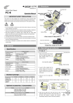
1
User Guide
T-25S-L (Coating Clamp)
T-25U-L (Coating Clamp)
DESCRIPTION
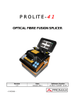
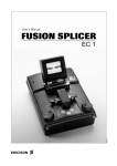
The T-25 is a fast compact fusion splicer, designed for joining optical fibres where the unit’s small
size and low weight are significant advantages, or where splicing performance requirements do
not justify the added cost and complexity of a core alignment splicer.
With good quality fibre the T-25 is capable of achieving extremely low loss splices when operated
according to this user guide.
T25 User Guide SPL035DO0004-00
FEATURES
The T-25 is a compact splicing system consisting of the following elements:
•
•
•
•
T-25 splicer with heatshrink oven
Rechargable internal battery BU-25
2-bay battery charger BC-25A
AC/DC mains adapter ADC-1635 and
mains lead for the battery charger
Internal battery
BU-25
AC/DC adapter
ADC-1635
T25 Splicer
Battery charger
BC-25A
In addition to the basic elements of the T-25 splicing system described above, the following
standard accessories are available:
•
•
•
•
•
•
•
•
•
FC-6S cleaver with automatic off-cut collection, for use with both 250 µm and 900 µm fibre
IF-25R Interface unit (mains input through the ADC1240 adapter, DC/serial output)
AC/DC adapter ADC-1240 for the interface unit IF-25R
Rechargeable internal batteries BU-65
Fibre stripper
Loose tube cutter
Fluid dispenser bottle
Electrodes ER-9
Neck strap
FC-6S Cleaver
AC/DC adapter
ADC-1240
IF-25R Interface unit
Page 2 of 12
Fluid dispenser
Electrodes ER-9
Fibre stripper
Loose tube cutter
© 2005 Sumitomo Electric Europe Limited
T25 User Guide SPL035DO0004-00
SAFETY
The T25 has been designed and manufactured to assure personal safety as far as is practically
possible. Improper or reckless use of this equipment could be hazardous and may result in fire,
electric shock or injury. The user should be aware of the following hazards and take suitable
precautions:
Arc (electric discharge) – the arc used to fuse the optical fibres is a high temperature
electric discharge (spark) that could ignite flammable or explosive gases or materials.
The electrodes and some parts of the heatshrink oven will become hot and should not be
touched.
The arc emits intense light that should not be viewed directly, e.g. with the wind cover
open. The splicer incorporates a video screen, which shows a magnified image of the
fibres for pre- and post-splice inspection of the fibres. This screen is completely safe to
view during the arc.
Electricity – the splicer (if using the IF-25R) and the battery charger BC-25A are mains
powered products that should not be used near water, wet surfaces or with wet hands.
Conductive materials such as metal wires or screwdrivers should not be poked into, or
used on, the splicer whilst it is plugged into any electrical supply.
Please use equipment only for its intended purpose, with approved accessories. If in doubt,
consult Sumitomo Electric Europe Ltd or your local Sumitomo representative.
© 2005 Sumitomo Electric Europe Limited
Page 3 of 12
T25 User Guide SPL035DO0004-00
PREPARING THE T25
Charging the battery:
Plug the ADC-1635 mains adapter into the external battery
charger BC-25A and insert one or both batteries for charging.
During charging the red LED by the battery will flash. When the
LED is on continuously, the battery is fully charged.
Caution: batteries may become hot whilst charging, and due
care should be taken
Inserting the internal battery:
Internal
connector
2. Insert battery
1. Open cover
Attaching and connecting the IF-25R interface unit:
1. Unscrew the finger screws and remove the blanking plate from the back of the T-25.
Blanking plate
Interface connection
Finger screws
2. Plug the Interface unit in at the back of the T-25 and tighten the finger screws
Mains Supply:
Plug the ADC-1240 mains adapter directly
into the IF-25R interface unit when fitted.
Page 4 of 12
© 2005 Sumitomo Electric Europe Limited
T25 User Guide SPL035DO0004-00
ADJUSTING THE SETTINGS
Navigating the settings menu system
From the initial ‘ready’ screen, the i button gives access to the settings menu shown below.
The menus can be navigated using the keypad as follows:
∧ and ∨: scroll up or down through menu items
Ready
O: select menu item
Up/down
buttons
∧ and ∨: toggle on/off options, or
increase/decrease numbers
i button
i : move back up to main menu
M: customise detailed splice program settings
(outside the scope of this manual)
O button
i , M SET OSTART
SM1 –60mm
Fibre type and heat-shrink sleeve settings:
The selected fibre type and heatshrink sleeve size are displayed in the bottom right corner of the
screen throughout the splicing process, and at the top of the main menu as shown below
Current fibre &
heatshrink
sleeve settings
Set up
SM1:SMF1c
60mm:FPS-1
Cond. Change
Arc Test
Function
Maintenance
Optical power
26/07/2004
15:40
i SPLICEOSELECT
Splice Cond.
SM1:SMF1c
MM1:MMF1c
Select SM1 for
single-mode
fibre
Select
“Condition
change”
Heater Cond.
40mm:FPS-40
60mm:FPS-1
MF-2:FPS-5
Select
heatshrink
sleeve
i BACK OSELECT
1. Select “SETTINGS”, then “Cond. Change”. Highlight the desired fibre type and press the O
“select” button.
2. Select the correct heat-shrink sleeve size.
Perform Arc Test
Performing an Arc test allows the splicer to optimise the arc for the current fibres and
environmental conditions. Please note, the arc test must be done with fibres in the splicer; the
ends of these fibres will be melted during the arc test and will need recleaving before splicing.
Set up
SM1:SMF1c
60mm:FPS-1
Cond. Change
Arc Test
Function
Maintenance
Optical power
26/07/2004
15:40
i SPLICEOSELECT
Select “Arc
Test”
Arc Test Ready
Arc Test
Y
X
L:021
R:021
Press the O
key to start
i , M SET OSTART
SM1 –60mm
Arc OK
Arc Count:
0009
SM1 –60mm
Good arc state
Splice can be done
SM1 –60mm
Power settings
Select “function” on the main menu to adjust power save settings and the “Auto Start” feature.
Function
P1
• Arc pause: if enabled, the T25 brings the fibre together but does not
Arc Pause
start the arc until the “O” button is pressed.
[OFF]
Sleep
• Sleep: switches off the monitor after programmable delay [OFF]
open/close the hood or press any button to wake it up
Power Off
[OFF]
•
Power off: switches off the splicer after programmable delay
Auto Start
[OFF]
• Autostart: splicer starts on closing hood
i BACL OSELECT
© 2005 Sumitomo Electric Europe Limited
Page 5 of 12
T25 User Guide SPL035DO0004-00
FIBRE PREPARATION:
1. Place a heat-shrink splice protection sleeve on one of the fibres prior to fibre preparation
for splicing.
2. Strip the coating of the fibre to reveal approximately 30 mm (1¼ inch) of bare cladding.
30 mm
3. Clean the bare fibre cladding with an alcohol (IPA) wetted lint free wipe (tissue or cloth).
This is best achieved by positioning the fibre in a folded wipe and pulling the cladding
through the wipe. The fibre should then be rotated by 90˚ and wiped a second time.
Rotate before
second wipe
4. The cleave length, e.g. the length of the bare fibre end, should be as follows:
a. 250 µm primary coated fibre:
b. 900 µm secondary coated,
tight buffered fibre:
c. 900 µm secondary coated,
loose buffered fibre:
10 mm
250 µm coating
125 µm cladding
10 mm
900 µm coating
900 µm loose
buffered coating
125 µm cladding
10 mm
10 mm
250 µm
coating
125 µm
cladding
CLEAVING THE FIBRE WITH THE FC-6S
1. Ensure the fibre cleaver has
a. the top clamp lever open
b. the coating clamp lid open
c. the off-cut collector lid open
d. the blade in the forward position.
Top
clamp
lever
open
Attached
collector
lid open
Coating
clamp
lid open
Blade carriage in forward position
Page 6 of 12
© 2005 Sumitomo Electric Europe Limited
T25 User Guide SPL035DO0004-00
2. The coating clamp on the FC-6S has two grooves, one for 250 µm primary coated fibre,
and one for 900 µm secondary coated/tight buffered fibre. Lower the fibre into the correct
groove without touching the exposed cladding, with the end of the fibre coating at the 10
mm mark on the ruler. Ensure also that the fibre is lying straight across the lower rubber
clamp pads. Carefully close the magnetic coating clamp lid to hold the fibre in place
Coating clamp lid
Cleave length: 10 mm
Coating
clamp
Blade
Groove for 900 µm fibre
Groove for 250 µm fibre
Rubber
clamp pads
Rubber clamp pads
3. Gently lower the off-cut collector lid (note: the off-cut lid does not close fully or ‘sit flush’ at
this stage) and then lower the clamp lever.
Lower
clamp
lever
Off-cut lid
not fully
closed
4. Slide the cleaver blade firmly to the rear of the cleaver.
Cleaver
blade
carriage
5. Open the clamp lever and the coating clamp, and lift the fibre from the cleaver.
Important: ensure the newly cleaved fibre end does not touch anything.
© 2005 Sumitomo Electric Europe Limited
Page 7 of 12
T25 User Guide SPL035DO0004-00
SPLICING THE FIBRES
The fibres are lowered into the splicer as illustrated below:
Fibre
exit pad
Coating
clamps
Centre
V-grooves
Front
guide
Middle
guide
Rear
guide
Fibre
exit pad
Centre of electrodes
1. Check the bare fibre length against the ruler on the coating clamp lid, ensuring the bare
fibre end does not touch the splicer, and then open the coating clamp lid.
2. Carefully lower the fibre into the fibre guides, with the fibre end as close to the centre of the
electrodes as possible. On 900 µm loose-buffered fibre, the end of the 900 µm coating
should be just at the front of the middle fibre guide.
Important: ensure the fibre end-face does not touch any part of the splicer or the other
fibre end.
3. Close the magnetic coating clamp lid and repeat step 1 to 3 for the second fibre.
4. Check that the fibre claddings are sitting in the splicer V-grooves
and the outer parts of the fibres pass through the padded
slots at the side of the splicer.
5. Splicing with the T-25 is extremely simple once the
fibres have been prepared and inserted as above.
Lower the lid of the splicer. If the splicer is set to
automatic, this will start the fully automatic splicing
process; otherwise, follow the instructions on the
screen and press the O button on the keypad to
start the splicing process.
Keypad
6. During the splicing process, the LCD screen will
display a magnified view of the fibre ends.
7. The T-25 will check the fibre ends, perform a
pre-splice cleaning arc, and complete the splice
if all is well.
Fold-out
LCD screen
8. The screen displays the following information during the splicing process:
Ready
Prefusion check
Arc
Postfusion check
Arc Complete
Complete
Remove Fibre
i , M SET OSTART
SM1 –60mm
Page 8 of 12
SM1 –60mm
Arc Count: 0 0 7 8
SM1 –60mm
Arc Count: 0 0 7 8
SM1 –60mm
Open Hood
i DATA
MARC
SM1 –60mm
© 2005 Sumitomo Electric Europe Limited
T25 User Guide SPL035DO0004-00
9. Upon successful completion of the splice the screen displays “Arc complete: open hood”.
In addition, the T25-S (but not the T25-U) can also display a splice loss estimate. Press the
iii data button before opening the hood for further information about the splice..
If the splice is unsatisfactory, another arc can be executed by pressing the M arc button
Splice Data
Arc Complete
Press i data
for splice data
Open Hood
i DATA
MARC
Offset
Cut L
Cut R
Gap
Press i back
Open
hood
Arc Complete
1.6 µm
0.5 deg
0.3 deg
23.4 µm
Complete
Remove Fibre
SM1-60mm
26/07/2004 17:16
Open Hood
i DATA
MARC
i BACK
SM1 –60mm
10. Alternatively, if the T-25 detects a problem with either fibre end, the screen will show the
problem fibre marked in red. Press the i button for a possible cause and solution.
Prefusion check
SM1 –60mm
POSSIBLE CAUSE
Crack on the fiber
end face
Cut Err (Crack)
i HELP
X RESET
OGO
Press i help
for possible
cause
i BACK
VNEXT
CAUTION
Recleave the
Fiber
Press V for
suggested
solutions
Clean the rubber
pads of the clamp
of the cleaver
i BACK
VNEXT
USING THE T25 HEAT-SHRINK OVEN
The standard splice protection technique for the T-25 utilises the built-in heat-shrink oven together
with either 40 mm or 60 mm splice protection sleeves.
1. Check that the T-25 is set to the correct size of heat-shrink sleeve; if necessary, change
the setting as described in the “Adjusting splicer settings” section.
2. Place a heat-shrink splice protection sleeve on one of the fibres prior to preparing the fibre
for splicing.
3. After splicing the fibres, open the magnetic clamps and remove the spliced fibre, handling
only by the coating and taking care that nothing touches the exposed glass.
4. Slide the splice protection sleeve over the splice taking care that there is an even length of
coating within either end of the sleeve.
5. Place the fibre and sleeve into the heat-shrink oven. Close the right clamp, pull the fibre
straight, then close the left clamp. Springs hold the fibre straight during this process.
Heat-shrink splice protection sleeve
Start button for
heatshrink oven
6. Press the heat button on the bottom right of the T25 keypad.
© 2005 Sumitomo Electric Europe Limited
Page 9 of 12
T25 User Guide SPL035DO0004-00
MAINTENANCE
The majority of splicing problems are caused by dust or debris contaminating the fibre, cleaver or
splicer. Care should be taken to maintain all parts of the splicing system in a clean condition to
ensure reliable service and a long life.
Changing electrodes
Before changing electrodes disconnect the T-25 from any external power supply and remove the
battery. The electrodes may be easily changed by undoing the thumb-screws indicated on the
electrode clamps. Do not touch the metal part of the electrodes, and ensure the new electrode is
fully inserted with the blue plastic against the electrode clamp when the thumb-screw is tightened.
Splicer “stage”
Thumb-screws on
electrode clamps
End of electrodes with
blue plastic cover
To execute the arc conditioning
programme, select “Maintenance”
on the main menu (navigate the
menu as described in the “Splicer
Settings“ chapter) followed by
“Conditioning Arc”.
Maintenance
Conditioning Arc
Restore Data
Reset Arc Count
0008
Select “Conditioning
Arc” to start programme
All Count
00000147
The programme
completes 30 arcs
i BACK OSELECT
When the Arc conditioning is complete,
select “Reset arc count”. The new
electrodes are now ready for use.
Maintenance
Conditioning Arc
Restore Data
Self Inspection
Reset Arc Count
0008
Conditioning Arc
Conditioning
1/30
i DATA
MARC
Reset Arc Count
Select “Reset
Arc Count”
Arc count has been
reset.
All Count
00000147
i BACK OSELECT
OOK
Restore data
The “Restore Data” function on the “Maintenance” submenu
allows the splicer settings to be restored, either to the factory
defaults or a previously saved set of values.
Select
“Restore Data”
All Count
00000147
i BACK OSELECT
Self inspection
When selected, the splicer automatically
runs through a series of tests on the main
components, e.g. the circuit board, the
motor drive, the optical unit and the heater.
Maintenance
Conditioning Arc
Restore Data
Self Inspection
Reset Arc Count
0008
All Count
00000147
i BACK OSELECT
Page 10 of 12
Maintenance
Conditioning Arc
Restore Data
Reset Arc Count
0008
Select “Self
Inspection”
Self Inspecting
Circuit Board
Motor Drive
Optical Unit
Heater
Good!
Good!
Good!
Good!
XCANCEL
© 2005 Sumitomo Electric Europe Limited
T25 User Guide SPL035DO0004-00
Disposal of fibre off-cuts (Sharps)
Fibre off-cuts or sharps must be disposed of properly and according to health and safety
regulations. Remove the off-cuts collection box and carefully empty into a suitable safety bin. Do
not attempt to remove any remaining off-cuts from the box with your fingers.
Cleaning splicer v-grooves, fibre guides and coating clamps
These can be cleaned with cotton buds and IPA. On no account should anything harder than a
sharp wooden stick be used to clean the fibre V-grooves in the coating clamps.
Cleaning cleaver blade and coating clamp
The cleaver blade, coating clamp grooves and fibre clamp pads can be cleaned with either cotton
buds or lint-free wipes and IPA.
Cleaning optics
The prisms in the wind hood can be cleaned with IPA and cotton buds/lint free wipes. The
microscope lens is situated beneath the electrodes. Always clean this when changing electrodes.
If more frequent cleaning is required, the electrodes can be removed and reinstalled as described
above. Perform the conditioning arc programme after reinserting the electrodes, but do not reset
the arc counter unless a new set of electrodes has been installed
Cleaver Blade Setting/Adjustment
The cleaver blade has 12 numbered settings, each of which will last for approximately 1000
cleaves. To move the blade to a new position loosen the blade securing screw, rotate the blade to
the next numerical position and tighten the blade securing screw.
Once all blade positions have been used a new blade must be fitted; please refer to the instruction
sheet supplied with the cleaver for advice on this procedure.
TROUBLESHOOTING
•
•
•
•
Necked fibre splice: bad cleave
or fibre slipping in coating clamp.
Clean coating clamps, re-cleave fibres and
ensure fibres are inserted correctly in splicer.
Bubble or black line:
For multimode fibres increase the pre-fusion
time and do an arc test.
For single-mode fibres this may indicate
non-identical fibres .
Kink or offset after splicing – probably caused
by an offset prior to splicing, perhaps due to
dirt in the splicer V-grooves or coating clamps.
Clean V-grooves and coating clamps, re-cleave
and ensure fibres are inserted correctly in splicer.
Necked fibre
Bubble in splice
Kinked fibre
Bump in fibre – overlap too big.
Use the “Restore Settings” option to reset an
incorrect splice programme setting to the factory
default. Otherwise contact the technical helpline.
Bump in fibre
© 2005 Sumitomo Electric Europe Limited
Page 11 of 12
T25 User Guide SPL035DO0004-00
SUPPORT CONTACT DETAILS
For product support, spares and servicing contact:
Technical helpline:
Email support:
+44 (0)208 953 1608
[email protected]
Address:
Sumitomo Electric Europe Ltd.
Unit 220, Centennial Park,
Centennial Avenue,
Elstree,
Herts.
WD3 3SL. UK
Main Tel:
Main Fax:
+44 (0)208 953 8118
+44 (0)208 953 8228
Website:
www.sumielectric.com
© 2005 Sumitomo Electric Europe Limited.
Original design, photographs and illustrations by Lucid Optical Services Ltd.
Printed in the UK by Lucid Optical Services Ltd.
Page 12 of 12
© 2005 Sumitomo Electric Europe Limited