1
INSTALLER:
Leave this manual with the appliance.
CONSUMER:
Retain this manual for future reference.
WARNING: If the information in these
instructions is not followed exactly a fire or
explosion may result causing property
damage, personal injury or death.
FOR YOUR SAFETY
Do not store or use gasoline or other
flammable vapours and liquids in the vicinity
of this or any other appliance.
WHAT TO DO IF YOU SMELL GAS
x
x
x
x
x
Do not try to light any appliance.
Do not touch any electrical Switch.
Do not use any phone in your building.
Immediately call your gas supplier
IURPDQHLJKERXU¶VSKRQH)ROORZWKH
JDVVXSSOLHU¶VLQVWUXFWLRQV
If you cannot reach your gas supplier
call the fire department.
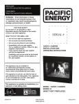
BROADWAY & BRENTWOOD
INSTALLATION AND
OPERATING INSTRUCTIONS
Installation and service must be performed
by a qualified installer, service agency or the
gas supplier.
This appliance may be installed in an
aftermarket permanently located,
manufactured home (USA only) or mobile
home, where not prohibited by local codes.
This appliance is only for use with the type of
gas indicated on the rating plate. This
appliance is not convertible for use with
other gases unless a certified kit is used.
MODEL: BROADWAY /
BRENTWOOD
This appliance is suitable for installation in a
bedroom or bed sitting room.
SERIES: A
DIRECT VENT GAS INSERT
090414 5055.66-‐B Important Note for the Commonwealth of M assachusetts:
From Massachusetts Rules and Regulations 248 CMR 5.08:
(a)
For all side wall horizontally vented gas fuelled equipment installed in every dwelling, building or structure used in whole or in part for residential purposes,
including those owned or operated by the Commonwealth and where the side wall exhaust vent termination is less than seven (7) feet above finished grade in the
area of the venting, including but not limited to decks and porches, the following requirements shall be satisfied.
1.
INSTALLATION OF CARBON MONOXIDE DETECTORS. At the time of installation of the side wall horizontal vented gas fuelled equipment, the
installing plumber or gas fitter shall observe that a hard wired carbon monoxide detector with an alarm and battery back-up is installed on the floor level where the
gas equipment is to be installed, in addition, the installing plumber or gas fitter shall observe that a battery operated or hard-wired carbon monoxide detector with
an alarm is installed on each additional level of the dwelling, building or structure served by the side wall horizontal vented gas fuelled equipment. It shall be the
responsibility of the property owner to secure the services of qualified licensed professionals for the installation of hard-wired carbon monoxide detectors.
a.
In the event that the side wall horizontally vented gas fuelled equipment is installed in a crawl space or an attic, the hard-wired carbon monoxide detector
with alarm and battery back-up may be installed on the next adjacent floor level.
b.
In the event that the requirements of this subdivision cannot be met at the time of completion of installation, the owner shall have a period of thirty (30) days
to comply with the above requirements; provided, however, that during said thirty (30) day period, a battery operated carbon monoxide detector with an alarm shall
be installed.
2.
APPROVED CARBON MONOXIDE DETECTORS. Each carbon monoxide detector as required in accordance with the above provisions shall comply
with NFPA 720 and be ANSI/UL 2034 listed as IAS certified.
3.
SIGNAGE. A metal or plastic identification plate shall be permanently mounted to the exterior of the building at a minimum height of eight (8) feet above
grade directly in line with the exhaust vent terminal for the horizontally vented gas fuelled heating appliance or equipment. The sign shall read, in print size no less
than one-KDOILQFKLQVL]H³*$69(17',5(&7/<%(/2:.((3&/($52)$//2%6758&7,216´
4.
INSPECTION. The state or local gas inspector of the side wall horizontally vented gas fuelled equipment shall not approve the installation unless, upon
inspection, the inspector observes carbon monoxide detectors and signage installed in accordance with the provisions of 248 CMR 5.089(2)(a) 1 through 4.
(b) EXEMPTIONS. The following equipment is exempt from 248 CMR 5.089(2)(a) 1 through 4.
1.
7KHHTXLSPHQWOLVWHGLQ&KDSWHUHQWLWOHG³(TXLSPHQW1RW5HTXLUHG7R%H9HQWHG´LQWKHPRVWFXUUHQWHGLWLRQRINFPA 54 as adopted by the Board; and
2.
Product Approved side wall horizontal vented gas fuelled equipment installed in a room or structure separate from the dwelling, building or structure used in
whole or in part for residential purposes.
(c)
MANUFACTURER REQUIREMENTS ± GAS EQUIPMENT VENTING SYSTEM PROVIDED. When the manufacturer of Product Approved side wall
horizontally vented gas equipment provides a venting system design or venting system components with the equipment, the instructions provided by the
manufacturer for installation of the equipment and the venting system shall include:
1.
Detailed instructions for the installation of the venting system design or the venting system components; and
2.
A complete parts list for the venting system design or venting system.
(d) MANUFACTURER REQUIREMENTS ± GAS EQUIPMENT VENTING SYSTEM NOT PROVIDED. When the manufacturer of a Product Approved
side wall horizontally vented gas fuelled equipment does not provide the parts for venting the fuel gases, but LGHQWLILHV³VSHFLDOYHQWLQJV\VWHPV´WKHIROORZLQJ
requirements shall be satisfied by the manufacturer.
1.
7KHUHIHUHQFHG³VSHFLDOYHQWLQJV\VWHP´LQVWUXFWLRQVVKDOOEHLQFOXGHGZLWKWKHDSSOLDQFHRUHTXLSPHQWLQVWDOODWLRQLQVWUXFWLons; and
2.
7KH³VSHFLDOYHQWLQJV\VWHPV´VKDOOEH3URGXFW$SSURYHGE\WKH%RDUGDQGWKHLQVWUXFWLRQVIRUWKDWV\VWHPVKDOOLQFOXGHDSDUWVOLVWDQd detailed installation
instructions.
(e))
A copy of all installation instructions for all Product Approved side wall horizontally vented gas fuelled equipment, all venting instructions, all parts
lists for venting instructions, and/or all venting design instructions shall remain with the appliance or equipment at the completion of the installation. 2 Table Of Contents
Caution.................................................................4
Safety...................................................................5
Owners Information
First Fire...............................................................6
Remote control.....................................................7
Maintenance.......................................................13
Lighting Instructions...........................................14
Installer information
Fireplace Dimensions........................................15
Existing Fireplace Preparation...........................16
Clearances to Combustibles..............................17
Surround Installation..........................................18
Venting...............................................................20
Plumbing and Electrical.....................................21
Gas Supply........................................................22
Gas Pressure Check / Output / Efficiency.........22
Gas Pressure Testing Procedure.......................23
Pilot Adjustment.................................................23
Propane Conversion..........................................24
Door Installation / Removal................................25
Fan Installation/ Removal..................................25
Panel Installation/Removal................................26
Log Burner Kit Installation/Removal..................27
Log Set Installation/Removal.............................28
Glass Burner Kit Installation/Removal...............29
Replacement Parts / Kits List.............................30
Wiring Diagram..................................................31
Notes..................................................................32
%URDGZD\5DWLQJ/DEHO««««««««««
Brentwood Rating /DEHO«««««««««« 3 Caution
FOR YOUR SAFETY - Do not install or operate your Pacific Energy appliance without first
reading and understanding this manual. Any installation or operational deviation from the
following instructions voids the Pacific Energy Warranty and may prove hazardous.
This appliance and its individual shut off valve must be disconnected from gas supply piping
system during any pressure testing of that system at test pressures in excess of 1/2 psig
(3.5 kPa).
This appliance must be isolated from the gas supply piping system by closing its individual
manual shut off valve during any pressure testing of the gas supply piping system at test
pressures equal to or less than 1/2 psig (3.5 kPa).
Do not use the fireplace if any part has been under water. Immediately call a qualified service
technician to inspect the fireplace and to replace any part of the control system and any gas
control which has been under water.
This unit must be installed with a Burner Set, Panel Set, and Surround Kit component. This fireplace is equipped with a micro mesh safety screen for your protection and
must be installed with the unit. Removal of the safety screen will cause the fireplace
to become a burn hazard. 4 Safety
x
Due to high temperatures, this gas appliance should be located out of traffic and away
from furniture and draperies.
x
Children and adults should be alerted to the hazards of high surface temperatures and
should stay away to avoid burns or clothing ignition.
x
Young children should be carefully supervised when they are in the same room as the
appliance. Toddlers, young children and others may be susceptible to accidental contact
burns. A physical barrier is recommended if there are at risk individuals in the house. To
restrict access to a fireplace or stove, install an adjustable safety gate to keep toddlers,
young children and other at risk individuals out of the room and away from hot surfaces.
x
Clothing or other flammable material should not be placed on or near the appliance.
x
A barrier designed to reduce the risk of burns from the hot viewing glass is provided with
the Surround Kit component and shall be installed.
x
If the barrier becomes damaged, the barrier shall be replaced with the manufacturers
barrier for this appliance.
x
Any grill, panel or door removed for servicing the unit must be replaced prior to operating.
x
Installation and repair should be done by a qualified service person. The appliance should
be inspected before use and at least annually by a professional service person. More
frequent cleaning may be required due to excessive lint from carpeting, bedding material,
etc. It is imperative that control compartments, burners and circulating air passageways of
the appliance be kept clean.
x
This appliance must not be connected to a chimney flue serving a separate solid fuel
burning appliance.
x
It is our policy that no responsibility is assumed by the Company or by any of its
employees or representatives for any damages caused by an inoperable, inadequate, or
unsafe condition which is the result, either directly or indirectly, of any improper operation
or installation procedures.
5 2:1(5¶6
INFORMATION
Congratulations on your purchase of a Pacific Energy Gas Appliance.
Your fireplace has been professionally installed by:
Dealer name: ___________________
Phone Number:_________________
If you discover any problems with your gas appliance contact your dealer immediately to have the
unit repaired.
Caution: Do not attempt to repair the fireplace because you may cause injury to yourself or others,
and risk causing damage to the unit.
Before operating your appliance carefully read this manual and pay close attention to all Safety
:DUQLQJV7KHPDQXDOFRQWDLQVLPSRUWDQWLQIRUPDWLRQRQWKHXQLW¶VVDIHRSHUDWLRQDQG
maintenance.
First Fire
When lit for the first time, the fireplace will emit a slight odor for a couple of hours. This is due to
the curing of paints, sealants and lubricants used in the manufacturing process. This condition is
temporary. Open doors and windows to ventilate area. Odor caused by the curing process may
cause discomfort to some individuals.
It is normal for fireplaces fabricated of steel to give off some expansion and/or contraction noises
during the start up or cool down cycle. Similar noises are found with your furnace heat exchanger
or cook stove oven.
6 ` Remote Control Operation
2:1(5¶6
INFORMATION
System Description
The Proflame Remote Control System consists of two elements:
1. Proflame Transmitter.
2. Proflame Integrated Fireplace Control (IFC) board and a wiring harness to connect the IFC
to the gas valve and stepper motor.
Transmitter (Remote Control with LCD Display)
The Proflame Transmitter uses a streamline design with a simple button layout and informative
LCD display (Fig. 1). The transmitter is powered by 3 AAA type batteries. A Mode key is provided
to Index between the features and a Thermostat key is used to turn on/off or index through
thermostat functions (Fig. 1 & 2). Figure 1: Proflame Transmitter
Figure 2: Transmitter LCD display
7 2:1(5¶6
INFORMATION
IFC Module
The Proflame 2 Integrated Fireplace Control (IFC) board is a device that allows the automatic
ignition and pilot flame supervision, to command the functions of a hearth appliance. It is
configured to control the ON/OFF main burner operation, giving the choice of both IPI (intermittent
pilot ignition), and CPI (continuous pilot ignition) modes.
The Proflame 2 IFC board controls and connects directly to the pilot assembly and an automatic
valve of the Proflame 880, 886 and 885 families using low electric power.
The IFC Board can be powered by an AC and battery pack for back up (ATMO Systems only). The
Proflame 2 offers the added ability to control the comfort fan speed from OFF through six (6)
speeds, a remotely actuated auxiliary outlet and a dimmable light outlet. The external batteries can
provide DC power to the IFC allowing the batteries to be used only when line power is interrupted
or lost.
OPERATING PROCEDURE
Initializing the System for the first time
Install the 4 AA batteries into the battery box. Note the polarity of the battery and insert into the
battery box as indicated on the Battery cover (+/-). Set the main ON/OFF and the CPI/IPI switch in
the closed position. Press the program EXWWRQRQWKH,)&PRGXOH7KH,)&ZLOO³EHHS´WKUHH
times to indicate that it is ready to synchronize with a Transmitter. Install the 3 AAA type batteries in
the battery bay, located on the base of the Transmitter. With the batteries installed in the
7UDQVPLWWHUSXVKWKH21EXWWRQ7KH5HFHLYHUZLOO³EHHS´IRXUWLPHVWRLQGLFDWHWKH7UDQVPLWWHU¶V
command is accepted. If a second Transmitter must be registered it can be turned ON. The
receiver will beep again four (4) times and exit the synchronization phase. If only one transmitter is
used, then press again the button program to exit the synchronization phase.
The system is now initialized.
8 2:1(5¶6
INFORMATION
Temperature indication Display
:LWKWKHV\VWHPLQWKH³2))´SRVLWLRQSUHVVWKH7KHUPRVWDW.H\DQGWKH
Mode Key at the same time. Look at the LCD screen on the transmitter to
verify that a C or F is visible to the right of the Room Temperature display.
(Fig. 3 & 4)
Turn on the Appliance
First close the main ON/OFF switch on the wirings. With the system OFF,
press the ON/OFF Key on the Transmitter. The Transmitter display will show
all active Icons on the screen. At the same time IFC will be commanded to
start the ignition process. Once the pilot flame is proven the IFC board will
open the main valve outlet and the appliance main burner will also ignite. A
VLQJOH³EHHS´IURPWKH,)&PRGXOHZLOOFRQILUPUHFHSWLRQRIWKHFRPPDQG
Turn off the Appliance
With the system ON, press the ON/OFF Key on the Transmitter. The
Transmitter LCD display will only show the room temperature. At the same
time the IFC will be commanded to turn off the burner. Depending on the
system mode (IPI or CPI) the pilot may shut off (IPI) or remain lit (CPI) and
WKHDSSOLDQFHEXUQHUWXUQV2))$VLQJOH³EHHS´IURPWKH5HFHLYHUFRQILUPV
reception of the command.
Figure 3: Display in Fahrenheit
Figure 4: Display in Celsius
Manual Bypass of the Remote System
If the batteries of the receiver or transmitter are low or depleted, the
appliance can be turned off manually using switch located on battery box.
This will bypass the remote control feature of the system.
Key Lock
This function will lock the keys to avoid unsupervised operation.
To activate this function, press the MODE and UP keys at the same time
(fig.5).
To de-activate this function, press the MODE and UP keys at the same time.
Figure 5
9 2:1(5¶6
INFORMATION
Remote Flame Control
The Proflame has six (6) flame levels. With the
system on, and the flame level at the maximum in
the appliance, pressing the down arrow key once
will reduce the flame height by one step until the
flame is turned off.
The Up Arrow Key will increase the flame height
each time it is pressed. If the Up Arrow Key is
pressed while the system is on but the flame is off,
the flame will come on in the high position. (Fig. 6)
$VLQJOH³EHHS´ will confirm reception of the
command.
Figure 6:
ROOM THERMOSTAT (Transmitter Operation)
The Remote Control can operate as a room thermostat. The
thermostat can be set to a desired temperature to control the
comfort level in a room.
To activate this function, press the Thermostat key (Fig. 1). The
LCD display on the transmitter will change to show that the room
thermostat is ³21´DQGWKHVHWWHPperature is now displayed
(Fig.7). To adjust the set point, press the up or down arrow keys
until the desired set point temperature is displayed on the LCD
screen of the transmitter.
Figure 7
Smart Thermostat (Transmitter Operation)
The Smart Thermostat function adjusts the flame height in
accordance to the difference between the set point and the room
temperatures. As the room temperature gets closer to the set point
the Smart Function will modulate the flame down. If the room
temperature is cool the Smart function will modulate the flame up.
To activate this function, press the THERMOSTAT key (Fig. 1)
until the word "SMART" appears to the right of the temperature
bulb graphic (Fig. 8). To adjust the set point, press the up or down
arrow keys until the desired set point temperature is displayed on
the LCD screen of the transmitter (Fig. 9).
Figure 8: Smart Flam
Function
Figure 9
10 2:1(5¶6
INFORMATION
Comfort Fan Speed Control
If the appliance is equipped with a hot air circulating fan, the speed of the fan can be
controlled by the Proflame system. The fan speed can be adjusted through six (6) speeds.
To activate this function use the Mode Key (fig.1) to index the fan control icon (Fig. 10).
Use the Up/Down Arrow Keys (Fig.1) to turn on, off or adjust the fan speed (fig. 10). A
VLQJOH³EHHS´ZLOOFRQILUPUHFHSWLRQRIWKHFRPPDQG
Figure 10: Fan Control
Continuous Pilot/Intermittent Pilot (CPI/IPI) selection
With the system in "OFF" position press the Mode Key (fig. 1) to index to the CPI mode
icon (fig.11).
Pressing the Up Arrow Key will activate the Continuous Pilot Ignition mode (CPI). Pressing
the 'RZQ$UURZ.H\ZLOOUHWXUQWR,3,$VLQJOH³EHHS´ZLOOFRQfirm the reception of the
command.
Figure 11: CPI/IPI Selection
11 2:1(5¶6
INFORMATION
Low Battery Power Detection
Transmitter
The life span of the remote control batteries depends on various
factors: quality of the batteries used, the number of ignitions of
the appliance, the number of changes to the room thermostat set
point, etc.
When the transmitter batteries are low, an Icon will appear on the
LCD display of the transmitter (Fig. 12) before all battery power is
lost. When the batteries are replaced this Icon will disappear.
Figure 12
Receiver
The life span of the IFC batteries depends on various factors: quality of the batteries used, the
number of ignitions of the appliance, the number of changes to the room thermostat set point,
etc.
When the IFC batteries are low, a "double-EHHS´ZLOOEHHPLWWHGIURPWKH,)&ERDUGZKHQLW
receives a command from the transmitter. This is an alert for a low battery condition for the IFC
ERDUG:KHQWKHEDWWHULHVDUHUHSODFHGWKH³EHHS´ZLOOEHHPLWWHGIURPWKH,)&ERDUGZKHQD
key is pressed (See Initialization of The System).
Warnings and Cautions
WARNING
Fire Hazard. Can cause severe injury or death
The Receiver causes ignition of the appliance. The appliance can turn on suddenly. Keep
away from the appliance burner when operating the remote system or activating manual
bypass of the remote system.
WARNING
Shock Hazard. Can cause severe injury or death
This device is powered by line voltage. Do not try to repair this device.
In no way is the enclosure to be tampered with or opened.
Disconnect from line voltage before performing any maintenance. 12 Maintenance
2:1(5¶6
INFORMATION
Turn off gas and electrical power supply (if applicable) and allow ample time for unit to cool
before servicing appliance. It is recommended that the fireplace and its venting should be
inspected at least once a year by a qualified service person.
Glass Door:
Warning: Do not operate fireplace with glass door removed, cracked or broken. Replacement of
the glass door should be done by a licensed or qualified service person.
Do not strike or otherwise impact the glass in any way that may cause it to break. If the glass
becomes cracked or broken it must be replaced before using the fireplace. Replacement door can be
obtained from your nearest Pacific Energy dealer. Do not substitute with any other type.
To remove broken glass, remove Door as noted in "Door Removal" section.
Annual Inspection:
a) Remove glass door and decorative media (such as logs and rocks). Inspect decorative media
and burner assemblies for soot buildup. If excessive buildup of soot is present, have a
qualified service person inspect and adjust unit for proper combustion. Clean burners with a
brush or vacuum cleaner, paying close attention to burner ports.
b)
Check the pilot system for proper flame size and operation. Clean pilot free of soot, dust or
any other deposits.
c) Check that the vent pipe and vent terminal are open and free from blockage or debris. If the
venting is disassembled for cleaning, it must be properly assembled and re-sealed. Refer to
VENTING section for proper procedure.
d) Check glass panel gasket, replace if necessary. It is important that the glass seal be
maintained in good condition.
e) Check and replace batteries as needed.
Note: The appliance area must be kept clear and free from combustible materials, gasoline and
other flammable vapors and liquids.
Periodically:
a) Viewing glass may be cleaned as necessary with fireplace glass cleaner.
b) Exterior finish may be cleaned with mild soap and water.
CAUTION:
Do not use abrasive cleaners on glass or any other part of the fireplace.
Do not clean glass when hot.
13 2:1(5¶6
INFORMATION
Lighting Instructions
14 Fireplace Dimensions
INSTALLER
INFORMATION
Broadway:
14 3/4͟ Figure 12: Broadway Dimensions
Brentwood:
Figure 13: Brentwood Dimensions
15 INSTALLER
INFORMATION
Existing Fireplace Preparation
The Broadway and Brentwood Gas inserts are certified to be installed into pre-existing approved
fire place cavities. The minimum cavity requirements are listed in Figure 14 below.
Dimension Broadway Brentwood A ϭϯ͟ ϭϱ͟ B Ϯϭ͟ Ϯϯ͟ C Ϯϲ͟ ϯϰ͟ Figure 14: Cavity Dimensions
Before installing the Broadway or Brentwood inserts have the chimney swept and fireplace,
including ash dumps and clean outs, cleaned to remove any creosote and soot residue that
may cause odors and stains after the insert has been installed. The fireplace chimney should
be in good working order and made of non-combustible material. Make sure chimney cleanouts
fit properly.
When preparing an existing fireplace to install a gas insert, any modifications that will
compromisHWKHLQWHJULW\RIWKHH[LVWLQJILUHSODFHDUHQRWDOORZHG7RPDNHZD\IRUWKHLQVHUW¶V
venting the fireplace flue dampener may be blocked open or removed. Refractory, glass doors,
screen rails, screen mesh and log grates can be removed from the fireplace before installing
the insert. Also, smoke shelves, shields and baffles may be removed if attached by mechanical
fasteners. Cutting any sheet metal parts of the fireplace, in which the gas fireplace insert is to
be installed, is prohibited.
If the factory-EXLOWILUHSODFHKDVQRJDVDFFHVVKROHVSURYLGHGDQDFFHVVKROHRI´
(37.5mm) or less may be drilled through the lower sides or bottom of the firebox in a proper
workmanship like manner. This access hole must be plugged with non-combustible insulation
after the gas supply line has been installed.
16 *MANTEL CLEARANCE Broadway Brentwood A ϮϬϭͬϮ͟ ϯϮ͟ B ϭϲ͟ ϯϮ͟ C ϭϭ͟ ϯϮ͟ ** MANTEL DEPTH D ϭϮ͟ E ϵ͟ F ϲ͟ ϭϲ͟ Minimum hearth depth As measured from glass Figure 15: Mantel Clearances
´
Figure 16: Sidewall Clearances
17 INSTALLER
INFORMATION
Clearances to Combustibles
INSTALLER
INFORMATION
Surround
Installation Instructions
Figure 18: Traditional Surround
Figure 17: Contemporary Surround
Installation
1. Fasten the surround base to the fireplace using supplied screws and mounting
holes located along the inner edge of the base.
2. Install the safety screen by aligning it with surround base and then pressing it into
place. Note: Install screen insuring the step faces inward.
3. Install the surround front by positioning it so as to clear the notches and secure by
applying a downward pressure in order to engage the locking tabs.
18 INSTALLER
INFORMATION
GBNT.SMBKA
GBWY.SMBKA
GBNT.SMBKOSA
GBWY.SMBKOSA
GBNT.STBKA
GBNT.STSSA
GBWY.STBKA
GBWY.STSSA
GBNT.STBKOSA
GBNT.STSSOSA
GBWY.STBKOSA
GBWY.STSSOSA
Figure 19: Surround Dimensions
19 INSTALLER
INFORMATION
Venting
Figure 21: Flue Adaptor Plate Conections
26¶-35
Full Closed
16¶-2
1/2 Open
¶-
Full Open
Min. Vent Height
¶(3m)
Figure 20: Venting
Figure 22: High Wind Vent Terminal
20 MAX. Vent Height
¶P
Intake Damper Position
Note: The following Simpson Duravent kits are
recommended for use with this
appliance.
High-Wind
(Broadway 46DVA-CL33)
(Brentwood 46DVA-CL34)
Prairie Co-Linear Kit
(Broadway 46DVA-CL33P)
(Brentwood 46DVA-CL34P)
Only certified venting systems or components may
be installed with this fireplace.
1) Measure chimney height, cut flex liner (min.10') as
required. Mark one pipe at both ends to identify
combustion air intake pipe from flue outlet pipe.
2) Attach marked flex liner pipe to the intake side of
vent terminal. Seal and secure with sealant and
screws provided. Attach the other pipe to the outlet
side of vent terminal. Seal and secure with sealant
and screws provided.
3) Insert both flex liners from top of the chimney, down
through the damper opening.
4) Before attaching vent terminal to top of chimney,
apply a bead of caulking to top of clay liner. Slip
vent terminal over liner and secure in place with
lateral retaining bolts.
5) For larger chimneys, an optional flashing is
available which may be cut and fitted to suit. The
flashing attaches to the underside of the terminal
with four nuts provided. Caulk the flashing in place
to seal any gaps.
Plumbing and Electrical
INSTALLER
INFORMATION
Figure 23: Gas and Electrical Connections
Note: Installation requires that an electrical outlet be installed into existing fireplace
cavity before insert is installed.
To make the required electrical and gas connections start by positioning the gas insert
within the existing fireplace. Connect the gas supply line to the 1/2´IOH[WXELQJWKDWH[WHQGV
out of the unit as seen in Figure 23. Please see the gas supply section of the manual for
requirements of the gas supply. Next, plug the power cord into the unit as shown in Figure
23 and plug them into the electrical outlet within the existing fireplace cavity.
NOTE: The appliance, when installed must be electrically grounded in accordance
with local codes or, in the absence of local codes, with the National Electrical
Code, ANSI/NFPA 70, or the Canadian Electrical Code, CSA C22.1. 21 INSTALLER
INFORMATION
Gas Supply
Servicing of the appliance can be performed from the front of the unit by removing the front trim, or by removing the
gas tray from the unit.
Caution: The gas line should be installed by a qualified service person in accordance with all building codes. This
section is intended as a guide for qualified technicians installing this appliance. Consult local and/or national building
codes before proceeding.
x
Gas supply line connection is located on the side of the insert. Gas connection accepts a 3/8" N.P.T. fitting.
Correct gas line diameter must be used to assure proper operation and pressure.
x
The fireplace input rating is shown in the chart below.
x
A drip leg must be installed in the gas supply line going to the gas control valve to -minimize the possibility of
any loose scale or dirt within the gas supply line from entering the control valve.
x
It is essential that a union or flanged connection be installed just upstream of the valve and inside the control
compartment to allow for repair or replacement of the gas valve.
Check local codes for additional requirements.
Turn on the gas supply and check that all connections are tight and leak free.
WARNING: The gas tray including gasket must be reinstalled after
conversion/installation or servicing has been completed.
Gas Pressure Check / Output / Efficiency
Please refer to following page for gas pressure testing procedure.
Gas pressure requirements
Broadway Input Pressure
Natural Gas
Propane
Minimum
Maximum
4.0" WC
13.9" WC
11.0" WC
13.9" WC
Manifold Pressure
High
Low
3.5" WC
1.6" WC
10" WC
6.4" WC
22 Gas NG LP Orifice Output 1.98mm 18,000 btu/hr 1.25mm 17,000 btu/hr AFUE 76% 76% Brentwood Gas NG LP Orifice Output 2.55mm 30,000 btu/hr 1.50mm 26,000 btu/hr AFUE 75% 75% Gas
Pressure Testing Procedure INSTALLER
INFORMATION
Note: To test the gas pressure, turn off the gas supply to the appliance before loosening
test point screws.
Verify gas pressures with the fireplace lit and at the highest setting.
1. Remove door (Fig. 28) and locate the valve as seen in Figure 24.
2. Locate the inlet and outlet test points on the valve which can be seen in Figure 25. After
locating test ports loosen the screws within the ports using a flat-tip screwdriver.
3. Attach pressure gauge to the test ports
4. Turn gas supply back on and test pressures.
5. After testing is finished turn off gas supply, remove the pressure gauges and retighten the
screws in the test points.
Pilot Adjustment
The pilot flame level can be adjusted by turning the adjustment screw, using a flat-‐
tip screwdriver, seen on the valve in Figure 25. Battery Box
Figure 24: Valve Location
Figure 25: Valve
23 INSTALLER
INFORMATION
Propane Conversion
Before starting the conversion make sure to shut
off the gas supply to the unit and allow fireplace
to cool to room temperature.
To convert the gas fireplace insert from natural gas to
propane the (GASC.LPKIT) kit is required. This kit
comes with new pilot and burner orifices as well as a
new pressure modulator for the valve.
To switch the pressure modulator follow the
instructions that are provided with the conversion kit.
Figure 26: Burner Orifice and Pilot
To change the orifices, remove the door, media set,
and burner. Please refer to the appropriate sections of
this manual and follow instructions on how to correctly
remove these components.
Pilot orifice sizes NG -‐ #62 LP -‐ #35 After removing the burner access the burner orifice
which is located on the bottom of the burner tray, as
seen in figure 26. The orifice can be removed using a
ò´VRFNHW%HIRUHLQVWDOOLQJWKHQHZRULILFH/RFWLWH
Thread Sealant needs to be applied to the threads of
the new orifice to ensure a proper seal when installed.
To replace the pilot orifice, remove the pilot hood
which is held in place by a spring. First remove the
spring, and then remove the hood by pulling it up from
the pilot bracket, seen in figure 27. To remove the
H[LVWLQJRULILFHLQVHUWD´RUPP$OOHQZUHQFK
into the hexagonal key-way of the orifice and rotate
until free. Insert the new orifice using the same Allen
wrench and tighten it until a torque of 9 lbf in (1 Nm) is
achieved. Replace the pilot hood by aligning the tab
on the base of the hood with the slot in the side of the
pilot journal, and push the hood down, onto the pilot
bracket. Replace the spring by pushing it into its seat.
Figure 27: Pilot
24 Door Installation/Removal
INSTALLER
INFORMATION
Installation
1. Position the door so that the doors
upper bracket is positioned overtop
of the lip on top of the firebox.
2. Lower the bottom edge of the door
and secure it with ´ bolts to the
relief arms as shown in figure 28.
Removal
Figure 28: Door
NOTE: In the event that the door glass breaks, The complete door assembly must be replaced. See replacement parts list for the appropriate part number. 1. Locate and remove the WZR´
bolts securing the bottom of door as
seen in figure 28.
2. Tilt the bottom of the door away
from the appliance and lift the door
off.
Fan Removal / Installation
Removal
1. Pull the fireplace insert out of the preexisting fireplace cavity until you have
access to the fan access panel on the back
of the fireplace. Figure 29
2. Remove screws from access panel and pull
fan out of unit, you will have to disconnect
wires to fan before you can remove
completely.
Figure 29: Fan Access Panel
Installation
1. Connect wiring to fan and insert into the fireplace through the back of the unit.
2. Insert all screws into the fan access panel to attach the fan to the unit.
3. Push the gas insert fireplace back into the fireplace cavity.
25 INSTALLER
INFORMATION
Panel Installation / Removal
Installation
NOTE: Air Deflector from burner kit needs to be
installed before panels. See Burner Kit Installation.
Insert back panel so that it is sitting on
1.
ledge at the back of the firebox as shown in
Figure 31.
2. Insert first side panel by inserting the front
edge of the panel into the lip at the front of
the firebox. Then slide the back of the panel
until it reaches the firebox side wall.
Figure 32.
3. Repeat steps 2 for the second side panel.
4. To hold panels in place, install the baffle,
from the burner kit, by resting the back
flange on top of the back panel and use two
screws to secure the front of the baffle to
the top of the firebox, seen in Figure 33.
Removal
1. Remove the baffle by removing screws
securing the front edge of the baffle seen in
Figure 33. After removing the two screws
you can slide the baffle out of the fireplace.
2. Remove first side panel by pulling the back
edge of panel out away from the firebox
wall until there is enough room to remove
the front edge of the panel from the lip at
front of firebox. When you have enough
URRPUHPRYHSDQHO¶VIURQWHGJHIURPWKH
firebox lip and remove from fireplace.
3. Repeat step 2 to remove second side
panel.
4. Remove back panel by tilting the top
forward and then pull out of fireplace.
Figure 30: Panel Set
Figure 31: Back Panel
Figure 32: Side Panel
Figure 33: Baffel Mounts
26 Log Burner Kit Installation / Removal
INSTALLER
INFORMATION
Air Deflector Installation / Removal
Installation
Position the air deflector in the fireplace as seen in
figure 34 and secure with two screws using a
screwdriver.
Removal
Remove the two screws seen in figure 34 using a
screwdriver, and remove the air deflector from
fireplace.
Figure 34: Air Deflector
Burner Tray Installation / Removal
Installation
Place the burner tray in the fireplace and secure with
4 screws using a screwdriver, as seen in figure 35.
Removal
Remove the 4 screws seen in figure 35 using a
screwdriver, and remove the burner tray.
Burner Installation / Removal
Installation
Place burner in firebox so that the venturi is over top
of the orifice. To secure burner insert screw using a
screwdriver as seen in figure 36.
Figure 35:Burner Tray Removal
Remove screw seen in figure 36 and lift burner out of
the unit.
Figure 36:Burner Figure 37:Burner Kit 27 INSTALLER
INFORMATION
Log Set Installation / Removal
Installation
1. Position rear log against the back firebox as
seen in Figure 39.
2. Position front log just behind the front burner
tube as seen in Figure 40.
3. Position log 3 with the thin end of the log
resting on top of the right end of the front log
as seen in Figure 41.
4. Place ember chunks in front of the front log to
hide the burner as seen in Figure 42.
Note: Do Not Block Burner Ports with
Embers
Figure 38: Log Set
Removal
1. Remove embers from fireplace.
2. Lift the decorative log off of the front log and
remove it from the firebox.
3. Lift the front log off of the burner and remove it
from the firebox.
4. Lift the back log over the pilot and burner and
remove from firebox.
Figure 39: Rear Log Installation
Figure 40: Front Log Installation
Figure 41: Decorative Log Installation
Figure 42: Ember Placement
Figure 43: Complete Log Set
28 Glass
Burner Installation / Removal
INSTALLER
INFORMATION
Air Deflector Installation / Removal
Installation
Position the air deflector in the fireplace as seen in
figure 44 and secure with two screws using a
screwdriver.
Removal
Remove the two screws seen in figure 44 using a
screwdriver, and remove the air deflector from
fireplace.
Figure 44: Air Deflector
Burner Tray Installation / Removal
Installation
Place the burner tray in the fireplace and secure with
4 screws using a screwdriver, as seen in figure 45.
Removal
Remove the 4 screws seen in figure 45 using a
screwdriver, and remove the burner tray.
Glass Installation
To install the glass, evenly spread a thin layer of
crushed glass across the entire burner pan as seen
in figure 46. Ensure glass does not cover pilot.
Figure 45:Glass Burner Tray
Rock Installation (Optional)
To install the optional rock set, place rocks making
sure no rocks are in the flame when the unit is
operating. Do not cover air openings.
Figure 46: Glass Installation
Figure 47: Glass Burner Kit
Figure 48: Rocks Installation
29 INSTALLER
INFORMATION
Replacement Parts
Description
Order Number
Broadway Replacement Door...........................................
Brentwood Replacement Door..........................................
Broadway Regular Screen................................................
Brentwood Regular Screen...............................................
Complete Replacement Gas Tray.....................................
Replacement Gas Valve...................................................
Replacement Control Module............................................
Replacement Pilot Assembly............................................
Replacement Remote Control...........................................
BDEM.DSPA
BRNT.DSPA
GBWY.SCRNA
GBNT.SCRNA
GASC.BRNTRAYA
GASC.VALVEA
GASC.MODA
GASC.PILOTA
GASC.CNTRLA
Broadway Aesthetic Components
Brentwood Aesthetic Components
Surround Kit (required)
Surround Kit (required)
BDWY TRADITIONAL SURROUND.........BDWY.SMBKA
BDWY OS TRADITIONAL SURROUND...BDWY.SMBKOSA
BDWY CONTEMPORY SURROUND.......BDWY.STBKA
BDWY OS CONTEMPORY SURROUND.BDWY.STBKOSA
BDWY CONTEMPORY SS SRNDND.......BDWY.STSSA
BDWY OS CONTEMPORY SS SRND......BDWY.STSSOSA
BRNT TRADITIONAL SURROUND.........BRNT.SMBKA
BRNT OS TRADITIONAL SURROUND... BRNT.SMBKOSA
BRNT CONTEMPORY SURROUND....... BRNT.STBKA
BRNT OS CONTEMPORY SURROUND. BRNT.STBKOSA
BRNT CONTEMPORY SS SRNDND....... BRNT.STSSA
BRNT OS CONTEMPORY SS SRND...... BRNT.STSSOSA
Panel Set (required)
Panel Set (required)
BDWY ESTM PANEL FLUTED................BDEM.CPNFLA
BDWY ESTM PANEL RED BRICK..........BDEM.CPNRDA
BDWY ESTM PANEL GRAY BRICK........BDEM.CPNGYA
%':<(6703$1(//('*(6721(«%'(0&31/'$
BDWY ESTM PANEL PORC BLACK......BDEM.PPNBKA
BDWY ESTM PANEL PORC RED...........BDEM.PPNRDA
BDWY ESTM PANEL PORC Titanium.....BDEM.PPNTIA
BDWY ESTM PANEL PORC Coffee Bean..BDEM.PPNCBA
BDWY ESTM PANEL PORC Copper.......BDEM.PPNCUA
BRNT ESTT PANEL FLUTED....................BRET.CPNFLA
BRNT ESTT PANEL RED BRICK............. BRET.CPNRDA
BRNT ESTT PANEL GRAY BRICK........... BRET.CPNGYA
%517(6773$1(//('*(6721(« BRET.CPNLDA
BRNT ESTT PANEL PORC BLACK.......... BRET.PPNBKA
BRNT ESTT PANEL PORC RED.............. BRET.PPNRDA
BRNT ESTT PANEL PORC Titanium........ BRET.PPNTIA
BRNT ESTT PANEL PORC Coffee Bean.. BRET.PPNCBA
BRNT ESTT PANEL PORC Copper.......... BRET.PPNCUA
Burner Set (required)
Burner Set (required)
BDWY ESTM DESIGNER LOG BNR.......BDEM.NG01A
BDWY ESTM GLASS BURNER...............BDEM.NG03A
BRNT ESTT DESIGNER LOG BNR............BRET.NG01A
BRNT ESTT GLASS BURNER....................BRET.NG03A
Optional Components
Optional Components
BDWY ESTM BLOWER....................
Metro Rock Set Black.......................
Metro Rock Set Grey........................
Tranquility Rock Set.........................
Propane Conversion Kit...................
BDEM.BLOWA
GASC.METROBKA
GASC.METROGYA
GASC.TRANQA
GASC.LPKIT
30 BRNT ESTT BLOWER.....................
Metro Rock Set Black.......................
Metro Rock Set Grey........................
Tranquility Rock Set.........................
Propane Conversion Kit...................
GBRET.BLOWA
GASC.METROBKA
GASC.METROGYA
GASC.TRANQA
GASC.LPKIT
INSTALLER
INFORMATION
Caution: Label all wires prior to
disconnection when servicing
controls. Wiring errors can cause
improper and dangerous operation.
Verify proper operation after
servicing. 31 INSTALLER
INFORMATION
NOTES: __________________________________________________________________________________________________
__________________________________________________________________________________________________
__________________________________________________________________________________________________
__________________________________________________________________________________________________
__________________________________________________________________________________________________
__________________________________________________________________________________________________
__________________________________________________________________________________________________
__________________________________________________________________________________________________
__________________________________________________________________________________________________
__________________________________________________________________________________________________
__________________________________________________________________________________________________
__________________________________________________________________________________________________
__________________________________________________________________________________________________
__________________________________________________________________________________________________
__________________________________________________________________________________________________
__________________________________________________________________________________________________
__________________________________________________________________________________________________
__________________________________________________________________________________________________
__________________________________________________________________________________________________
__________________________________________________________________________________________________
__________________________________________________________________________________________________
__________________________________________________________________________________________________
__________________________________________________________________________________________________
__________________________________________________________________________________________________
__________________________________________________________________________________________________
__________________________________________________________________________________________________
__________________________________________________________________________________________________
__________________________________________________________________________________________________
__________________________________________________________________________________________________
__________________________________________________________________________________________________
__________________________________________________________________________________________________
__________________________________________________________________________________________________
__________________________________________________________________________________________________
__________________________________________________________________________________________________
__________________________________________________________________________________________________
__________________________________________________________________________________________________
__________________________________________________________________________________________________
__________________________________________________________________________________________________ 32 INSTALLER
INFORMATION
33 INSTALLER
INFORMATION
34 INSTALLER
INFORMATION
35 INSTALLER
INFORMATION
Technical support: 1-250-748-1184
Web site: www. pacificenergy.net
2975 Allenby Rd., Duncan, BC V9l 6V8
36