1
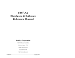
es
MCC-300 Console
User’s Guide
Telecor Inc.
Intended for use in TII/XL Systems
running Version 6.4 Firmware
November 2006
Man. Rev. 2.2
1114 Westport Cr.
Mississauga, Ontario
Canada, L5T 1G1
Tel: (905) 564-0801
Fax: (905) 564-0806
www.telecor.com
LIMITED WARRANTY POLICY
Telecor Inc. warrants all products bearing the Telecor name to be free from defects of material and workmanship under
normal use and service for a period of one year from date of delivery. Telecor will repair or replace (at our option), free
of charge, any unit that is found to be defective and returned to us under warranty. Telecor warrants all other products
made by others, and distributed by us, to be covered by the manufacturers' warranty period.
This warranty shall not apply to any Telecor products that have been subject to misuse, neglect, accident, modification,
water, fire, lightning, paint, or used in violation of instructions furnished, repaired or altered outside of the factory. This
warranty does not cover batteries, bulbs, fuses or damage caused by batteries used in connection with the product.
Telecor reserves the right to make the final decision on whether there is a defect in materials or workmanship, and
whether or not the product returned is within the warranty period.
This warranty covers bench repairs only. Telecor will not be responsible for any costs incurred involving on-site service
calls. Repair or replacement by others, fire, transportation, labour charges, indemnity, etc., are not covered by this
warranty and no responsibility for same will be assumed by us. Our liability does not extend to consequential damage.
AUTHORIZED REPAIR STATION:
All participating Distributors and Dealers are authorized to accept Telecor products for return to
us for repair or replacement, or customers may return goods to us directly, providing that return
authorization has been obtained.
U.S. CUSTOM ERS are required to ship any Returns or Repairs to:
Telecor Inc.
2434 Jerauld Avenue
* U.S. customers must not
Niagara Falls, New York
return products to Canada.
U.S.A., 14305
CANADIAN and ALL OTHER CUSTOM ERS are required to ship any Returns or Repairs to:
Telecor Inc.
1114 W estport Crescent
Mississauga, Ontario
Canada, L5T 1G1
For details on Telecor’s Return Policy, see our Published Merchandise Return Policy.
For TII/XL Firmware Version 6.4
E:\T2-OPER\REV2\T2-OPER.wp/mm
ETS 1607
© Copyright 1995-2006 by Telecor Incorporated. All rights reserved. No part of this publication may be reproduced
in any form, or by any means, without the prior written permission of Telecor Incorporated.
Telecor Inc. makes no representation of warranties with respect to this manual. Further, Telecor reserves the right to
make changes in the specifications of the products described in this manual at any time without notice, and without
obligation of Telecor to notify any persons of such revisions or changes.
Telecor and the Telecor logo are registered trademarks of Telecor Inc.
www.telecor.com
FCC NOTICE
PRODUCT NAM E:
ADMINISTRATIVE CONSOLE
M ODEL NUM BER:
MCC-300
FCC RULES:
THIS PRODUCT HAS BEEN TESTED TO COMPLY W ITH FCC PART 15,
SUBPART B, CLASS A – UNINTENTIONAL RADIATORS
OPERATING ENVIRONM ENT: FOR USE IN COMMERCIAL AND INDUSTRIAL AREAS
FCC Compliance Statem ent:
This device com plies with Part 15 of the FCC Rules. Operation is subject to the following two conditions:
(1) this device m ay not cause harm ful interference and (2) this device m ust accept any interference
received, including interference that m ay cause undesired operation.
FCC Notice:
This equipm ent has been tested and found to com ply with the lim its for a Class A digital device, pursuant
to Part 15 of the FCC Rules. These lim its are designed to provide reasonable protection against harm ful
interference when the equipm ent is operated in a com m ercial environm ent. This equipm ent generates,
uses, and can radiate radio frequency energy and, if not installed and used in accordance with the
instruction m anual, m ay cause harm ful interference to radio com m unications. Operation of this equipm ent
in a residential area is likely to cause harm ful interference in which case the user will be required to
correct the interference at his own expense.
FCC W arning:
Changes or m odifications not expressly approved by Telecor could void the user’s authority to operate the
equipm ent.
The Party Responsible for Product Com pliance:
Telecor Inc.
1114 W estport Crescent,
Mississauga, Ontario
Canada, L5T 1G1
Table of Contents
A . Introduction. . . . . . . . . . . . . . . . . . .
A.1 Overview of the MCC-300 Console.
Character Display. . . . . . . . . . . .
Contrast Adjustm ent. . . . . . . . . .
Volum e Control. . . . . . . . . . . . . .
Special Function Keys. . . . . . . . .
Intercom Channel Keys. . . . . . . .
Program Channel Keys. . . . . . . .
Help and Display Call Keys. . . . .
.
.
.
.
.
.
.
.
.
.
.
.
.
.
.
.
.
.
.
.
.
.
.
.
.
.
.
.
.
.
.
.
.
.
.
.
.
.
.
.
.
.
.
.
.
.
.
.
.
.
.
.
.
.
.
.
.
.
.
.
.
.
.
.
.
.
.
.
.
.
.
.
.
.
.
.
.
.
.
.
.
.
.
.
.
.
.
.
.
.
.
.
.
.
.
.
.
.
.
.
.
.
.
.
.
.
.
.
.
.
.
.
.
.
.
.
.
.
.
.
.
.
.
.
.
.
.
.
.
.
.
.
.
.
.
.
.
.
.
.
.
.
.
.
.
.
.
.
.
.
.
.
.
.
.
.
.
.
.
.
.
.
.
.
.
.
.
.
.
.
.
.
.
.
.
.
.
.
.
.
.
.
.
.
.
.
.
.
.
.
.
.
.
.
.
.
.
.
.
.
.
.
.
.
.
.
.
.
.
.
.
.
.
.
.
.
.
.
.
.
.
.
.
.
.
.
.
.
.
.
.
.
.
.
.
.
.
.
.
.
.
.
.
.
.
.
.
.
.
.
.
.
.
.
.
.
.
.
.
.
.
.
.
.
.
.
.
.
.
.
.
.
.
.
.
.
.
.
.
B . Operating Procedures. . . . . . . . . . . . . . . . . . . . . . . . . . . . . . . . . . . . . . . . . .
B.1 Call Processing. . . . . . . . . . . . . . . . . . . . . . . . . . . . . . . . . . . . . . . . . . . . . . .
Calling a Room . . . . . . . . . . . . . . . . . . . . . . . . . . . . . . . . . . . . . . . . . . . . .
Auto Callback. . . . . . . . . . . . . . . . . . . . . . . . . . . . . . . . . . . . . . . . . . . . . .
Calling Another Console. . . . . . . . . . . . . . . . . . . . . . . . . . . . . . . . . . . . . .
Answering a Call-in. . . . . . . . . . . . . . . . . . . . . . . . . . . . . . . . . . . . . . . . . .
Viewing and Answering Call-ins in the System Queue. . . . . . . . . . . . . . .
Placing a Call on Hold. . . . . . . . . . . . . . . . . . . . . . . . . . . . . . . . . . . . . . . .
Taking a Call off Hold. . . . . . . . . . . . . . . . . . . . . . . . . . . . . . . . . . . . . . . .
Transferring a Call.. . . . . . . . . . . . . . . . . . . . . . . . . . . . . . . . . . . . . . . . . .
Answering a Transferred Call. . . . . . . . . . . . . . . . . . . . . . . . . . . . . . . . . .
Forwarding Calls to Another Console. . . . . . . . . . . . . . . . . . . . . . . . . . . .
Forwarding Calls from Another Console. . . . . . . . . . . . . . . . . . . . . . . . . .
Preventing Calls at your Console. . . . . . . . . . . . . . . . . . . . . . . . . . . . . . .
Placing Em ergency Calls. . . . . . . . . . . . . . . . . . . . . . . . . . . . . . . . . . . . .
Forwarding Unanswered Priority Calls. . . . . . . . . . . . . . . . . . . . . . . . . . .
B.2 Paging. . . . . . . . . . . . . . . . . . . . . . . . . . . . . . . . . . . . . . . . . . . . . . . . . . . . . .
Making a Single Room Page. . . . . . . . . . . . . . . . . . . . . . . . . . . . . . . . . . .
Making an All Call Page. . . . . . . . . . . . . . . . . . . . . . . . . . . . . . . . . . . . . .
Making an Em ergency Page. . . . . . . . . . . . . . . . . . . . . . . . . . . . . . . . . . .
Making a Zone Page. . . . . . . . . . . . . . . . . . . . . . . . . . . . . . . . . . . . . . . . .
Monitoring a Page Zone . . . . . . . . . . . . . . . . . . . . . . . . . . . . . . . . . . . . . .
Excluding Room s from Pages. . . . . . . . . . . . . . . . . . . . . . . . . . . . . . . . . .
B.3 Program Distribution. . . . . . . . . . . . . . . . . . . . . . . . . . . . . . . . . . . . . . . . . . .
Distributing an Audio Program to All Locations. . . . . . . . . . . . . . . . . . . . .
Distributing an Audio Program to the Selected Room s List. . . . . . . . . . .
Distributing an Audio Program to Program Zones. . . . . . . . . . . . . . . . . .
Distributing an Audio Program to the Selected Room s List and Program
Monitoring an Audio Program . . . . . . . . . . . . . . . . . . . . . . . . . . . . . . . . . .
Custom izing the Selected Room s List.. . . . . . . . . . . . . . . . . . . . . . . . . . .
B.4 Tone Distribution. . . . . . . . . . . . . . . . . . . . . . . . . . . . . . . . . . . . . . . . . . . . . .
B.5 System Clock Functions. . . . . . . . . . . . . . . . . . . . . . . . . . . . . . . . . . . . . . . .
Changing the System Tim e. . . . . . . . . . . . . . . . . . . . . . . . . . . . . . . . . . . .
Selecting 12 or 24-Hour Form at . . . . . . . . . . . . . . . . . . . . . . . . . . . . . . . .
Setting the Day, Month, and Year. . . . . . . . . . . . . . . . . . . . . . . . . . . . . . .
Disabling/Enabling Autom atic Daylight-Saving Tim e Correction. . . . . . . .
B.6 Electronic Message Displays & Clock Messaging. . . . . . . . . . . . . . . . . . . . .
Activating a Message on the Electronic Message Display (EMD) . . . . . .
Activating a Message on the 2.5" or 4" Digital Clock . . . . . . . . . . . . . . . .
Autom atic Bell Message Feature. . . . . . . . . . . . . . . . . . . . . . . . .
B.7 Schedules. . . . . . . . . . . . . . . . . . . . . . . . . . . . . . . . . . . . . . . . . . . . . . . . . . .
Enabling/Disabling Schedules. . . . . . . . . . . . . . . . . . . . . . . . . . . . . . . . . .
Clearing All Schedules. . . . . . . . . . . . . . . . . . . . . . . . . . . . . . . . . . . . . . .
B.8 System Settings. . . . . . . . . . . . . . . . . . . . . . . . . . . . . . . . . . . . . . . . . . . . . .
View Console Operating Firm ware Version. . . . . . . . . . . . . . . . . . . . . . .
View System Operating Firm ware Version. . . . . . . . . . . . . . . . . . . . . . . .
.
.
.
.
.
.
.
.
.
.
.
.
.
.
.
.
.
.
.
.
.
.
.
.
.
.
.
.
.
.
.
.
.
.
.
.
.
.
.
.
.
.
.
.
.
.
.
.
.
.
.
.
.
.
.
.
.
.
.
.
.
.
.
.
.
.
.
.
.
.
.
.
.
.
.
.
.
.
.
.
.
.
.
.
.
.
.
.
.
.
.
.
.
.
.
.
.
.
.
.
.
.
.
.
.
.
.
.
.
.
.
.
.
.
.
.
.
Page
Page
Page
Page
Page
Page
Page
Page
Page
A-1
A-1
A-2
A-2
A-2
A-3
A-3
A-3
A-4
.......
.......
.......
.......
.......
.......
.......
.......
.......
.......
.......
.......
.......
.......
.......
.......
.......
.......
.......
.......
.......
.......
.......
.......
.......
.......
.......
Zones. .
.......
.......
.......
.......
.......
.......
.......
.......
.......
.......
.......
.......
.......
.......
.......
.......
.......
.......
.
.
.
.
.
.
.
.
.
.
.
.
.
.
.
.
.
.
.
.
.
.
.
.
.
.
.
.
.
.
.
.
.
.
.
.
.
.
.
.
.
.
.
.
.
.
.
.
.
.
.
.
.
.
.
.
.
.
.
.
.
.
.
.
.
.
.
.
.
.
.
.
.
.
.
.
.
.
.
.
.
.
.
.
.
.
.
.
.
.
.
.
.
.
.
.
.
.
.
.
.
.
.
.
.
.
.
.
.
.
.
.
.
.
.
.
.
.
.
.
.
.
.
.
.
.
.
.
.
.
.
.
.
.
.
.
.
.
.
.
.
.
.
.
.
.
.
.
.
.
.
.
.
.
.
.
.
.
.
.
.
.
.
.
.
.
.
.
.
.
.
.
.
.
.
.
.
.
.
.
.
.
.
.
.
.
.
.
.
.
.
.
.
.
.
.
.
.
.
.
.
.
.
.
.
.
.
.
.
.
.
.
.
.
.
.
.
.
.
.
.
.
.
.
.
.
.
.
.
.
. Page B-1
. Page B-1
. Page B-2
. Page B-2
. Page B-2
. Page B-3
. Page B-4
. Page B-4
. Page B-4
. Page B-4
. Page B-5
. Page B-5
. Page B-5
. Page B-6
. Page B-6
. Page B-7
. Page B-8
. Page B-8
. Page B-8
. Page B-9
. Page B-9
Page B-10
Page B-10
Page B-11
Page B-11
Page B-12
Page B-13
Page B-14
Page B-15
Page B-15
Page B-16
Page B-17
Page B-17
Page B-18
Page B-18
Page B-19
Page B-20
Page B-20
Page B-21
Page B-22
Page B-23
Page B-23
Page B-24
Page B-25
Page B-25
Page B-25
View System Configuration. . . . . . . . . . . . . . . . . . . . . . . . . . . . . . . . . . . . . . . . . . . . . . . . Page B-25
C.
C.1
C.2
C.3
Appendices.. . . . . . . . . . . . . . . . . . . . . . . . . . . . . . . . . .
Error Messages. . . . . . . . . . . . . . . . . . . . . . . . . . . . . . .
Resetting the System .. . . . . . . . . . . . . . . . . . . . . . . . . .
System Priority Levels. . . . . . . . . . . . . . . . . . . . . . . . . .
Single and Dual Channel Com m unication System s.
C.4 Electronic Message Display Quick Reference Guide. .
.
.
.
.
.
.
.
.
.
.
.
.
.
.
.
.
.
.
.
.
.
.
.
.
.
.
.
.
.
.
.
.
.
.
.
.
.
.
.
.
.
.
.
.
.
.
.
.
.
.
.
.
.
.
.
.
.
.
.
.
.
.
.
.
.
.
.
.
.
.
.
.
.
.
.
.
.
.
.
.
.
.
.
.
.
.
.
.
.
.
.
.
.
.
.
.
.
.
.
.
.
.
.
.
.
.
.
.
.
.
.
.
.
.
.
.
.
.
.
.
.
.
.
.
.
.
.
.
.
.
.
.
.
.
.
.
.
.
.
.
.
.
.
.
.
.
.
.
.
.
.
.
.
.
.
.
.
.
.
.
.
.
.
.
.
.
.
.
.
.
.
.
.
.
Page
Page
Page
Page
Page
Page
C-1
C-1
C-2
C-3
C-3
C-4
A . Introduction
This guide is designed to help you use the MCC-300 Administrative Console for effective and
efficient operation of the Telecor Communication System.
The Telecor System is a two-way voice communications system that allows administrative staff to
directly communicate with those at locations equipped with room speakers, telephones and other
consoles, and conduct paging throughout all or different areas of the facility. The ability to distribute
audio programs and tones, and enable or disable system clock schedules, can also be conducted from
the Console. Please read this guide carefully to ensure proper operation of the MCC-300 Console.
A.1 Overview of the MCC-300 Console
The MCC-300 is a desktop telephone-style unit that allows for two-way communications to take
place on the Telecor System. The diagram below illustrates the main components of the MCC-300
Console.
MCC-300 User’s Guide
Page A-1
Character Display
The MCC-300 is equipped with a backlit LCD Display that makes it easy to read in low-light
conditions. The display can even be tilted at different angles to allow for optimum viewing.
The Console supports a 2-line by 20-character display.
When the Console is not in use, the Console model and
number appear on the top line, and the time and date appear
on the second line.
Main Status Display
When a call rings at the Console, the display changes to
show the call-in type and Room number.
Call Status Display
Contrast Adjustment
The MCC-300 includes a control on the right side of the
housing to adjust the contrast of the character display. Insert
an appropriate-sized flathead screwdriver to turn the
control. Turning clockwise increases the contrast and
turning counterclockwise decreases the contrast.
Volume Control
These keys adjust both the speaker listen and handset listen volumes. To adjust the
handset listen volume, lift up the handset and listen to the audio. Press the up arrow
to increase the volume, or the down arrow to decrease the volume.
To adjust the speaker listen volume, while listening to the audio from the speaker,
press the up arrow to increase the volume, or the down arrow to decrease the
volume.
Page A-2
Introduction
Special Function Keys
The MCC-300 has two special function keys: the Time Function key and Program Function key.
The Time Function Key allows you to:
•
•
•
•
•
•
The Program
•
•
•
•
Change the system time
Selected 12 or 24-hour format
Set the year, month, and day
Enable/disable automatic
daylight-saving time correction
Enable/disable, or clear schedules
Distribute tones to all speakers
Function Key
allows you to:
Forward console calls
Customize the Selected Rooms List
Monitor program distribution (e.g. music)
Reset the system
Intercom Channel Keys
PAGE -initiates
HOLD -places
CANCEL
a paging announcement.
the current call on hold.
ends most Console functions.
PUSH TO TALK
places and answers calls and controls the direction
of communication between Consoles and Rooms.
Program Channel Keys
ALL ROOM S
initiates Program Distribution (e.g. music) to all Rooms.
SELECTED ROOM S
M IC
selects the microphone as an audio source.
TAPE
selects the cassette player as an audio source.
TUNER
AUX
MCC-300 User’s Guide
initiates Program Distribution to certain Rooms.
selects the radio as an audio source.
selects the CD player as an audio source.
Page A-3
Help and Display Call Keys
HELP
displays the Error Code when an error message appears on the d
DISPLAY CALL
Page A-4
displays the calls that are waiting in the queue.
Introduction
B . Operating Procedures
This section provides step-by-step procedures for operating the MCC-300 Console. Using the
Console, you can manage the following activities:
Call Processing
Paging
Program Distribution (e.g. Music)
Tone Distribution
Time Functions
Enable/Disable Bell Schedules
B.1 Call Processing
Call Processing refers to how the Console operator makes calls, handles incoming calls, and
connects calls from one Console or Room to another. Prior to performing any of these tasks, you
must become familiar with the following Console practices:
•
Both the speaker and handset can be used for Console-to-Room communication as well
as Paging. However, for the best sound quality, using the handset is recommended.
•
Only the handset can be used for Console-to-Console communication. This ensures private
two-way communication between operators.
•
To control the direction of communication during a call, use the PUSH TO TALK button. Press
and hold it when you're talking, and release it when you're listening. This function is referred
to as PTT mode.
•
If VOX (Voice Operated Switching) mode is enabled on your Console, you can talk hands
free.1 The Console speaker picks up the sound of your voice and automatically transmits it
without you pressing any buttons. In instances where background noise may interfere with
VOX, you can easily switch to PTT mode by pressing the PUSH TO TALK button (doing this
would disable VOX until the next call). Instructions provided in this User’s Guide
assume that VOX is disabled.
1
Check with your system administrator to enable/disable VOX.
MCC-300 User’s Guide
Page B-1
Calling a Room
1.
Enter the Room dial number.
•
2.
The dial number appears on the display.
Press PUSH TO TALK .
•
A tone sounds at the Console and at the Room Station.
3.
Lift up the handset to talk.
or
To use the Console speaker/mic, press and hold PUSH TO TALK (release it to listen).
4.
To end the call, hang up the handset or press CANCEL .
Auto Callback
When you receive a busy signal when calling a room (a repeating tone is heard through the handset),
you can activate the Auto Callback feature to automatically receive a call back from the room you
attempted to call when an audio channel is free.
1.
Upon hearing the busy signal, press the * key and then dial 66 .
2.
Hang up the handset.
3.
Wait to receive a call back from the room once an audio channel is free for communications.
Calling Another Console
Both parties must use the handsets for Console-to-Console communication.
1.
Lift up the handset.
2.
Press #.
3.
Enter the Console number.
4.
Press PUSH TO TALK .
•
5.
A tone sounds at the other Console and its display shows your Console number. The
other Console operator must lift up the handset to answer your call.
To end the call, either party can hang up the handset or press CANCEL .
Page B-2
Operating Procedures
Answering a Call-in
The system allows for six different call-in types to be made at the Console. A call-in type has a
separate priority level to determine its importance in relation to other call-in types. When a call-in
type is received at the Console, the Console identifies it by sounding a distinct tone and displaying
the call-in type description. The table below lists the available call-in types:
Call-in Type
Priority Level
Console Display
Description
Emergency Level 1
0 (highest)
EMERG 1: (flashing)
Emergency Level 2
1
EMERG 2:
Priority Level 1
2
PRIORITY 1: (flashing)
Priority Level 2
3
PRIORITY 2:
Staff Call
4
STAFF CALL
Room Call
5 (lowest)
NORM. CALL
If several call-ins are made at the Console, the Console displays the call-in with the highest priority.
For several call-ins with the same priority level, the Console displays them on a first-come first-serve
basis. A call-in that is not displayed waits in the system queue.
To answer a call-in type:
1.
Lift up the handset
or
To use the Console speaker/mic, press and hold PUSH TO TALK to speak (release it to listen).
2.
To end the call, hang up the handset or press CANCEL .
MCC-300 User’s Guide
Page B-3
Viewing and Answering Call-ins in the System Queue
Call-ins that are not immediately answered by a Console are placed into the system queue. The
MCC-300 is able to display these queued call-ins and answer any waiting call-in, regardless if the
call-in was made to another Console.
1.
Press DISPLAY CALL repeatedly to scroll through the calls that are waiting in the queue.
•
Calls are displayed by priority level and on first-come first-serve basis.
2.
Scroll to the call you want to answer, then lift up the handset.
or
To use the Console speaker/mic, press and hold PUSH TO TALK to speak (release it to listen).
Note:
W hen scrolling, press CANCEL to return to the first call in the queue.
Placing a Call on Hold
1.
While the call is in progress, press HOLD .
•
The display shows ON HOLD next to the caller’s Room number. The on-hold call is
placed in the queue.
Taking a Call off Hold
To take the call off hold, it must be displayed on the Console (use DISPLAY CALL if necessary).
When the call on hold is displayed, lift up the handset or to use the Console speaker/mic, press and
hold PUSH TO TALK to speak (release it to listen).
Transferring a Call
1.
Press HOLD to place the call on hold.
2.
Call the Console (remember to use handset) that you want to transfer the call to.
3.
Inform the Console operator of the call to be transferred.
4.
Hang up the handset or press CANCEL to transfer the call.
Page B-4
Operating Procedures
Answering a Transferred Call
When a call has been transferred from another Console, it is placed in the queue where it waits to
be answered.
1.
Press DISPLAY CALL to find the transferred call.
2.
Lift up the handset.
or
Press and hold PUSH TO TALK to speak (release it to listen).
Forwarding Calls to Another Console
To have your calls forwarded to another Console, you must inform the other Console operator to take
your calls. The other Console operator must then forward calls from your Console (see below) to her
Console.
Forwarding Calls from Another Console
To have calls forwarded to your Console from another Console, add the Console to your Console
list. Each Console in this list has its calls forwarded to your Console. The list also includes the
proprietary Console number (the number of the Console that the list is being displayed on).
To add a Console to the Console list:
1.
Press PROGRAM
•
FUNCTION , 9 ,
then *.
The display shows the Console list (press # and * to scroll forward and backward
through the list).
2.
Press the Console number to add to the list, followed by *.
3.
Use the # and * keys to scroll through the list to see that the Console number has been added.
4.
Press 0 followed by * to exit the Console list.
To remove a Console from the Console list:
1.
Press PROGRAM
•
FUNCTION , 9 ,
then *.
The display shows the Console list.
2.
Press # and * until the Console number to be removed appears on the display.
3.
Press CANCEL to remove the Console number.
4.
Press 0 followed by * to exit the Console list.
MCC-300 User’s Guide
Page B-5
Preventing Calls at your Console
If another Console is set up to receive your calls (see “Forwarding Calls from Another Console,”
page B-5), then you can set up your Console to not receive call-ins by removing it from the Console
list. This will prevent calls from ringing on your Console.
Note:
A Console cannot be rem oved from a list unless another C onsole has taken over its calls. This
ensures that all calls in the system will always be dealt with.
To remove your Console from the Console list:
1.
Press PROGRAM
•
FUNCTION , 9 ,
then *.
The display shows the Console list.
2.
Press # and * until your Console number appears on the display.
3.
Press CANCEL to remove your Console number.
4.
Press 0 followed by * to exit the Console list.
Placing Emergency Calls from a Room Phone to the MC-300
An Emergency Call-in can be placed to a MCC-300 Console from a Room telephone in two
ways: Dial 0# or Dial 91.
For Dial 0#:
1.
User picks up the Room Phone and presses 0# on the telephone keypad. Press 0#.
•
The Emergency Call will be placed to the default console. The user may hang up
the phone, but the call-in will remain on the MCC-300.
To Place an Emergency Call-in using the 91 feature:
1.
User picks up the room phone and presses 91 on the telephone keypad.
•
The Emergency Call will be placed to the default console. The user may continue
to dial any other digits, or hang up the phone, but the call-in will remain on the
MCC-300.
To turn off this feature, do the following:
1.
Press PROGRAM
Page B-6
FUNCTION, 910,
then *.
Operating Procedures
The second way activated by default. If it is deactivated you can reactivate it by:
1.
Press PROGRAM
•
FUNCTION, 911,
then *.
The feature is now activated on your system.
Forwarding Unanswered Priority Call-ins
If a priority call-in is not answered, this feature allows your console to automatically forward the
call-in, to all connected consoles, after it has gone unanswered for a preset period of time. The
amount of time can be from 5 seconds to 120 seconds.
To enable this feature perform the following steps:
1.
Press TIM E FUNCTION , 7 then *.
•
2.
The feature is now activated. The display will show - - PROGRAM M ING - - 120 .
This is the default setting of 120 seconds when the feature is first activated.
Type the amount of delay, in seconds, for example 30 , before an emergency call is
forwarded, then *.
•
The emergency call-in delay is now set system wide to the number entered.
•
You can check to make sure your entry has been accepted by pressing TIM E
FUNCTION, 7 then *. The display will show - - PROGRAM M ING - - 30 .
MCC-300 User’s Guide
Page B-7
B.2 Paging
Paging allows you to broadcast announcements throughout a facility. The system allows for four
types of pages:
Single Room Page
All Call
Emergency
Zone Page
Making a Single Room Page
A Single Room Page will page a single Room equipped with a speaker. It recommended to use
the handset to make the page.
1.
Lift the handset.
2.
Enter the room number to be paged.
3.
Press PAGE and then PUSH TO TALK .
4.
Make the page.
5.
To end the page, hang up the handset.
Making an All Call Page
An All Call Page will page every location that is equipped with a speaker, including Rooms,
corridors, and outdoor areas. It is recommended to use the handset to make the page.
1.
Lift the handset.
2.
Press PAGE , 0 , then PUSH TO TALK .
3.
Make the page.
4.
To end the page, hang up the handset
Page B-8
Operating Procedures
Making an Emergency Page
An Emergency Page will page every location that is equipped with a speaker, including Rooms,
corridors, and outdoor areas. This page has a higher system priority level than the All Call Page.
If both should occur at the same time, the Emergency Page overrides the All Call Page. For more
information on system priority levels, see page C-3.
1.
Lift the handset.
2.
Press PAGE , then PUSH TO TALK .
3.
Make the page.
4.
To end the page, hang up the handset
Making a Zone Page
A building can be separated into 32 Page Zones.1 A page can be made to one or several of these
Zones without disturbing other areas of the facility. It is recommended to use the handset to make
the page.
To make a page to a temporary Page Zone list, complete the following steps:
1.
Lift the handset.
2.
Enter the Zone number followed by *. Repeat this step for other Zones to be included in
the list (maximum 32 Zones). To remove a Zone from the list, enter its number followed
by *.
Note: To scroll through the Page Zones that have been added to the list, press *.
3.
When all Zones have been added, press PUSH TO TALK .
4.
Make the page.
5.
To end the page, hang up the handset
1
Page Zones are set up by your system administrator. These may or may not be the same as Program Zones or Time
Zones.
MCC-300 User’s Guide
Page B-9
Monitoring a Page Zone
The system allows you to monitor a Page Zone over the Console speaker for unauthorized
activity or security purposes. Complete the following steps:
1.
Enter the Page Zone.
2.
Press PUSH TO TALK .
•
3.
The selected Zones are open to monitoring.
Press CANCEL to terminate the monitor function.
Note:
During Zone Monitoring, the system cannot receive incoming calls from
room stations and calls cannot be initiated to room stations.
Excluding Rooms from Pages
Rooms can be placed in the Page Exclusion List so that they will not receive Zone Pages, Time
Zones and Program Distribution over the room speaker. This function does not exclude
Emergency Pages, Intercom Calls and Remote Tones/Pages.
1.
Press PROGRAM
•
FUNCTION, # .
The display shows Room Numbers (2 to 4 digits) or – (list is empty).
2.
To scroll down the list of Rooms press *. To scroll up the list of Rooms press # .
3.
To add a Room to the list enter the Room Number followed by *. To remove a Room
from the list press CANCEL when the Room Number appears on the display.
4.
To save the new list press PROGRAM
5.
To exit programming mode enter 0, *.
FUNCTION , 20 ,
*.
The system features an option to have the Page Exclusion List cleared at midnight. To enable this
press PROGRAM FUNCTION , 21 , *.
Page B-10
Operating Procedures
B.3 Program Distribution
Program Distribution refers to when an audio program is broadcast to a particular location. An
audio program may originate from a radio, CD or cassette player, or microphone. It can be
distributed to Rooms, Zones, or both.
There are two types of program distribution: low priority and high priority. Basically, a higher
priority program distribution is less likely to be interrupted by another system action. See
“System Priority Levels,” page C-3 for further details and a list of system priorities.
Distributing an Audio Program to All Locations
This procedure distributes an audio program to every location that is equipped with a speaker,
including Rooms, corridors, and outdoor areas. To distribute audio to all speakers, complete the
following steps:
1.
Press ALL ROOM S .
•
The display shows P .
2.
For high priority program distribution, press *. For low priority, do not press anything
and proceed to the next step.
3.
Select an audio source: TAPE , TUNER , or AUX . For a microphone, press M IC and then the
Microphone number (1-5).
4.
The audio source is heard through the Console speaker.
Note: To cancel an audio source, press TAPE , TUNER , or AUX a second time. To turn a
microphone off, press M IC , then 0 .
5.
Press PUSH TO TALK to start program distribution.
To monitor an audio program, see page B-14.
To cancel a program distribution:
1.
For a low priority program distribution, press ALL ROOM S and then CANCEL .
2.
For a high priority program distribution, press ALL ROOM S , press *, and then CANCEL .
MCC-300 User’s Guide
Page B-11
Distributing an Audio Program to the Selected Rooms List
The system allows you to customize a list of Rooms or Zones that can receive an audio program.
You can easily add or remove Rooms or Zones from this list at any time from the Console. To
view or customize the Selected Rooms List, see “Customizing the Selected Rooms List,” page B14.
To distribute audio to the Selected Rooms List, complete the following steps:
1.
Press SELECTED ROOM S .
•
The display shows P .
2.
For high priority program distribution, press *. For low priority, do not press anything
and proceed to the next step.
3.
Select an audio source TAPE , TUNER , or AUX . To select a mic, press M IC and then the
Microphone number (1-5).
4.
The audio source is heard through the Console speaker.
Note: To cancel an audio source, press TAPE , TUNER , or AUX a second time. To turn a
microphone off, press M IC , then 0 .
5.
Press PUSH TO TALK to start program distribution.
•
The program is distributed.
To monitor an audio program, see page B-14.
To cancel a program distribution:
1.
For a low priority program distribution, press SELECTED ROOM S and then CANCEL .
2.
For a high priority program distribution, press SELECTED ROOM S , press *, and then
CANCEL .
Page B-12
Operating Procedures
Distributing an Audio Program to Program Zones
A building can be separated into 31 Program Zones.1 A program can be distributed to one or
several of these Zones without disturbing other areas of the facility. To distribute audio to a
temporary Program Zone list, complete the following steps:
1.
Press SELECTED ROOM S .
•
2.
The display shows P .
Enter the Program Zone number followed by #. Repeat this step for other Program Zones
to be included in the list (maximum 31 Zones). To remove a Zone from the list, enters its
number followed by *.
Note: To scroll through the Program Zones that have been added to the list, press #.
3.
For high priority program distribution, press *. For low priority, do not press anything
and proceed to the next step.
4.
Select an audio source TAPE , TUNER , or AUX . To select a mic, press M IC , and then the
Microphone number (1-5).
5.
The audio source is heard through the Console speaker.
Note: To cancel an audio source, press TAPE , TUNER , or AUX a second time. To turn a
microphone off, press M IC , then 0 .
6.
When all Program Zones have been added, press PUSH TO TALK to start program
distribution.
To monitor an audio program, see page B-14.
To cancel a program distribution:
1.
For a low priority program distribution, press SELECTED ROOM S and then CANCEL .
2.
For a high priority program distribution, press SELECTED ROOM S , press *, and then
CANCEL .
1
Program Zones are set up by your system administrator. These may or may not be the same as Page Zones or Time
Zones.
MCC-300 User’s Guide
Page B-13
Distributing an Audio Program to the Selected Rooms List and Program Zones
The MCC-300 Console can also distribute an audio program to the Selected Rooms List and any
number of Program Zones (to view or customize the Selected Rooms List, see “Customizing the
Selected Rooms List,” page B-14 ). To distribute audio to the Selected Rooms List and one or
several Program Zones, complete the following steps:
1.
Press SELECTED ROOM S .
•
The display shows P .
3.
Enter the Program Zone number followed by #. Repeat this step for other Program Zones
to be included in the program distribution (maximum 31 Zones).
4.
Press 32 followed by # to choose the Selected Rooms List.
5.
For high priority program distribution, press *. For low priority, do not press anything
and proceed to the next step.
6.
Select an audio source TAPE , TUNER , or AUX . To select a mic, press M IC , and then the
Microphone number (1-5).
7.
The audio source is heard through the Console speaker.
Note: To cancel an audio source, press TAPE , TUNER , or AUX a second time. To turn a
microphone off, press M IC , then 0 .
8.
Press PUSH TO TALK to start program distribution.
To monitor an audio program, see page B-14.
To cancel an audio program:
1.
For a low priority program distribution, press SELECTED ROOM S and then CANCEL .
2.
For a high priority program distribution, press SELECTED ROOM S , press *, and then
CANCEL .
Page B-14
Operating Procedures
Monitoring an Audio Program
1.
Press PROGRAM
•
2.
FUNCTION , 8 ,
then * to monitor Program Distribution.
The audio source is heard through the Console speaker.
Repeat Step 1 to turn off monitoring.
Customizing the Selected Rooms List
1.
Press PROGRAM
2.
Press # or * to scroll forward or backward through the list.
•
FUNCTION ,
then * to enter the Selected Rooms List.
The display shows Room Numbers (2 to 4 digits), Program Zones (1-31), or – (list
is empty).
3.
To add a Room/Zone to the list, enter the number followed by *. To remove a
Room/Zone from the list, press CANCEL when the number appears on the display.
4.
Press 0 followed by * to exit the Selected Rooms List.
MCC-300 User’s Guide
Page B-15
B.4 Tone Distribution
Tone Distribution allows you to distribute one of eight possible Tones to all locations equipped
with a speaker, including Rooms, corridors, and outdoor areas.1 This feature can be used, for
instance, when you want to manually signal a class change.
To distribute a tone to all locations:
1.
Press TIM E FUNCTION .
2.
Enter the Tone number (1-8).
3.
Press PUSH TO TALK .
Note:
Conducting a Tone Distribution has the highest system priority. For more
information see “System Priority Levels,” page C-3.
1
Tone characteristics (how the Tone sounds) can be modified by your system administrator.
Page B-16
Operating Procedures
B.5 System Clock Functions
The following system clock functions can be accessed by a Console user:
Changing System Time
Selecting 12 or 24-Hour Format
Setting the System Day, Month and Year
Disabling/Enabling Automatic Daylight Saving Time Correction
The Telecor System has a Programming Key Switch to allow only authorized personnel access to
the programmable features of the system. Most of the Clock functions are protected by the
programming key.
The Programming Key is located on the front of the Power Supply Unit (PSU). The
Programming Key must be turned to the PROGRAM position before a user is able to change the
system’s programming. When programming is complete, return the Programming Key to the
RUN position and remove the key.1
Changing the System Time
By default, the time on the Telecor system is set to Eastern Standard Time. To change the time
on the Telecor system, complete the following steps:
1.
Turn the Programming Key to the PROGRAM position.
2.
Press TIM E FUNCTION .
3.
Enter the time in the format DHHMM, where:
D = Day of Week (Sun=0, Mon=1, etc.)
HH = Hour in 24-Hour Format (9 a.m.= 09, 1 p.m.= 13, etc.)
MM = Minutes (00 to 59)
4.
Press *.
5.
Turn the Programming Key back to the RUN position.
1
It is important to return the Program Key to the RUN position after programming is complete. Not only does this prevent
from unauthorized tampering, but it also protects the Telecor System memory from accidental erasure (such as what can occur
during an electrical storm).
MCC-300 User’s Guide
Page B-17
Selecting 12 or 24-Hour Format
By default, the system displays time on all Console displays in a 12-hour format. To select a 12
or 24-hour format for all Console displays, complete the following steps:
1.
Turn the Programming Key to the PROGRAM position.
2.
For 12-hour format, press TIM E FUNCTION then 1 .
or
2.
For 24-hour format, press TIM E FUNCTION then 2 .
3.
Press *.
4.
Turn the Programming Key back to the RUN position.
Setting the Day, Month, and Year
The date on the system is set at the Telecor factory located in Toronto, Canada. To change the
day and month on the Telecor system, complete the following steps:
1.
Press TIM E FUNCTION .
2.
Press 5 , then *.
3.
Enter the month and day in M M DD format. For example, for July 1st, enter 0701 .
4.
Press *.
5.
Turn the Program Key back to the RUN position.
To change the year on the Telecor system, complete the following steps:
1.
Turn the Program Key to the PROGRAM position or enter the Programming Access Code.
2.
Press TIM E FUNCTION .
3.
Press 4 ,then *.
4.
Enter the year. For example, enter 2005 .
5.
Press *.
6.
Turn the Program Key back to the RUN position.
Page B-18
Operating Procedures
Disabling/Enabling Automatic Daylight-Saving Time Correction
By default, Automatic Daylight-Saving Time Correction is enabled on the system. This means
that the system clock will automatically spring forward and fall back during a seasonal time
change.
Note:
Telecor recommends that after correctly setting the time (see page B-16),
that the date is also reset (see page B-17) to ensure Automatic DaylightSaving Time adjusts on the proper day.
To disable Automatic Daylight-Saving Time Correction, complete the following steps.
1.
Turn the Program Key to the PROGRAM position or enter the Programming Access Code.
2.
Press TIM E FUNCTION .
3.
Press 7 , 0 , then * to disable Automatic Daylight-Savings Time Correction.
4.
Turn the Program Key back to the RUN position.
To enable Automatic Daylight-Saving Time Correction, complete the following steps:
1.
Turn the Program Key to the PROGRAM position or enter the Programming Access Code.
2.
Press TIM E FUNCTION .
3.
Press 7 , 1 , then * to enable Automatic Daylight-Saving Time Correction.
4.
Turn the Program Key back to the RUN position.
MCC-300 User’s Guide
Page B-19
B.6 Electronic Message Displays & Clock Messaging
With the Clock Messaging feature, pre-programmed messages can be activated for display on
Telecor Electronic Message Displays (EMDs)1, and alphanumeric codes can be activated for
display on Telecor 2.5" or 4" digital clocks.
Activating a Message on the Electronic Message Display (EMD)
A building can be separated into 8 Clock Zones.2 A pre-programmed message can be distributed
to one or several of these Zones. Check with your system administrator for a list of the preprogrammed messages. To display a message to a Clock Zone(s), complete the following steps:
1.
Lift up the handset.
2.
Press the PROGRAM
3.
Enter the Message number (1–29). To enter a one-digit Message number, press 0
followed by the number (e.g. 01 for 1, 02 for 2, etc)
4.
Enter the Clock Zone number (0–8) that the message will display in. Enter 0 to select all
Clock Zones.
5.
Press * to display the message.
1
2
FUNCTION
key, followed by 7.
EMD were previously sold under the description ADC (Advanced Digital Clocks).
Clock Zones are set up by your system administrator.
Page B-20
Operating Procedures
Activating a Message on the 2.5" or 4" Digital Clock
The following messages can be displayed on the 2.5" or 4" clocks using the Console.
BELL (low priority)
8888 - to verify the clock display segments are functioning.
BELL (high priority)
FIRE
ExxE (where xx is a two-digit number) - used for Coded Messages (to be interpreted by
staff only.) A coded message can alert personnel of emergencies or concerns without
alarming the entire institution. For example, E06E could be used to signal that someone
requires immediate medical attention.
To display a clock message, complete the following steps:
1.
Press the PROGRAM FUNCTION button.
2.
Press 7, xx, and * (where xx is 01-99, see table below).
•
The message appears on the clocks and on the Console display.
IF xx IS:
FUNCTION
50
The clocks will display BELL (low priority).
90
The clocks will display 8888
93
The clocks will display BELL (high priority).
96
The clocks will display FIRE
99
The clocks will clear other messages and display
the time.
Any other two-digit
number
(for example, 06)
The clocks will display ExxE (for example,
E06E). Note that the Es will flash on the clock
displays.
If more than one message is activated (by different operators), the highest priority message is
displayed. Message priority is determined by the two-digit code to activate the message, with 01
being the lowest priority and 98 being the highest priority.
Note:
The above messages can also be activated from a contact switch or
pushbutton. Please see your authorized service technician for more
information. If a message is activated from a contact switch or
pushbutton, pressing PROGRAM FUNCTION 7, 99, * will clear the
message from the digital clocks only. The message will remain on the
Console display until cleared from the contact switch or pushbutton.
MCC-300 User’s Guide
Page B-21
Page B-22
Operating Procedures
Automatic Bell Message Feature
The Bell Message feature enables BELL to be displayed on the 2.5" and 4" clocks whenever a
bell tone sounds within the building. Either the higher priority BELL message (93) or the lower
priority BELL message (50) can be displayed (see table on previous page for message priorities).
Complete the following steps:
3.
Turn the Programming Key to the PROGRAM position on the front of the Power Supply
Unit (PSU).
4.
Enter one of the following Console key sequences depending on the desired function.
Console Key
Sequence
5.
Function
TIME FUNCTION, 82, *
Automatically displays BELL (with a higher
priority of 93) when a bell tone is activated.
TIME FUNCTION, 81, *
Automatically displays BELL (with a lower
priority of 50) when a bell tone is activated.
TIME FUNCTION, 80, *
Disables this feature
When programming is complete, return the Programming Key to the RUN position and
remove the key.1
1
It is important to return the Program Key to the RUN position after programming is complete. Not only does this prevent
from unauthorized tampering, but it also protects the Telecor System memory from accidental erasure (such as what can occur
during an electrical storm).
MCC-300 User’s Guide
Page B-23
B.7 Schedules
A Schedule is used to activate system events throughout the day(s), such as bell tones, clock
messages, music distribution, etc.1 The system has 16 Schedules that can be enabled. Multiple
Schedules can operate simultaneously.
Having different Schedules provides flexibility of using one Schedule for a regular day and
others for special days. For instance, in a school setting, you might use one Schedule for a
regular school day, and another one for a shorter school day.
Enabling/Disabling Schedules
Turn the Program Key to the PROGRAM position or enter the Programming Access Code.
1.
Press TIM E FUNCTION .
2.
Press 5 , 9 , then *.
•
3.
The display shows the Schedules that are currently enabled.
Enter the Schedule number followed by * to add a Schedule or remove an existing
Schedule.
Note: To scroll through the Schedules that are enabled, press *.
4.
Press CANCEL to return to the Main Status Display.
5.
Turn the Program Key back to the RUN position.
1
Schedules are set up by your system administrator. Schedules 1 to 8 can include two types of Events: 1.
Bell Tone - sounds a tone over a selected Time Zone(s) (group of speakers set up by your administrator), and 2.
Nighttime Mode - causes all Digital Secondary Clocks to blink only once every 5 seconds instead of staying
continuously lit, thereby preserving the lifetime of the clock displays. Schedules 9 to 16 can also include three other
types of Events: 3. Clock Messaging - displays a message on Advanced Digital Clocks (ADC-4-MAs) in a selected
Clock Zone(s). These are also referred to as EMDs. 4. Music - plays a selected music source over a selected Time
Zone(s). 5. Relay - activates a device via an output point.
Page B-24
Operating Procedures
Clearing All Schedules
1.
Turn the Program Key to the PROGRAM position on the PSU, or enter the Programming
Access Code on the Console.
2.
Press TIM E FUNCTION .
3.
Press 5 , 0 , then *.
•
4.
The Console returns to the Main Status Display.
Turn the Program Key back to the RUN position.
MCC-300 User’s Guide
Page B-25
B.8
System Settings
The Console can display its operating firmware and certain system configuration settings.
View Console Firmware Version
To view the Console Firmware version complete the following steps:
1.
Press PROGRAM
FUNCTION ,
72, *.
View System Configuration
To view certain system configuration settings complete the following steps:
FUNCTION ,
90, *.
1.
Press PROGRAM
2.
The display enters a list of system settings. Press * to scroll through the list. The
following is an explanation of each setting. Note that most settings can be enabled or
disabled. If enabled, on appears beside the setting. If disabled, off appears beside the
setting.
XL: Indicates that the system is a Telecor XL system.
TII: Indicates that the system is a Telecor II system.
12 HR: This indicates the time displayed on all the Consoles is in 12-hour format.
24 HR: This indicates the time displayed on all the Consoles is in 24-hour format.
E(on)(off): Emergency Call Upgrade. This setting allows any room to upgrade a normal
call-in into an Emergency Level 1 Call-in.
FD(on)(off): Fixed Digit Dialing. This eliminates the need for Single Line Consoles
(SLCs) and Telecor room phone users to enter * as a terminator when placing a call.
DST(on)(off): Automatic Daylight-Savings Time Correction. With this feature enabled,
the system automatically springs forward or falls back during a time change without
requiring the user to access the Time Function command.
60 Hz: Clock Synchronization. When this feature is enabled, the Central Processing Unit
(CPU-3) of the Telecor System measures the 50/60 Hz power line signal to determine if it
is accurate. If the signal is accurate, the Real Time Clock (RTC) in the system is
automatically synchronized to that signal.
Page B-26
Operating Procedures
ATOM: Atomic Clock Correction. With this feature enabled the system is programmed
to automatically set the time and date based on data received from an Atomic Clock
Decoder.
RPCH(on)(off): Reduced Priority For Calls on Hold. By enabling this feature, priority
call-ins placed on hold will be reduced to the lowest Priority Level. This enables
subsequent priority call-ins to be displayed on the Console display while the call-ins on
hold remain in the Console's queue.
ACC(on)(off): Automatic Call-in Cancellation. This feature applies in situations when a
classroom telephone places a call to a designated Console. With this feature enabled, the
call-in will ring at the designated Console only while the classroom telephone that is
placing the call is off-hook. If the handset is placed back on-hook, the call-in to the
Console will automatically be cancelled.
DDCC(on)(off): Disable Default Console Call-in. This feature disables the ability to call
the default Console by pressing # on a telephone. This will also disable the feature that
causes a handset to automatically call the Console if it is off-hook for more than 2
minutes.
DBG(on)(off): Debug Mode. When this feature is enabled, the System will send back
debugging information to Tel-Terminal, which can be used to troubleshoot the System.
MW(on)(off): Message Waiting. When enabled, this feature allows Console operators to
activate a “Message Waiting” LED in a classroom. The LED flashes to silently indicate
that there is a message waiting for the teacher.
ABML(on)(off): Automatic Bell Messaging Low Priority. Enabling this feature allows
the low priority BELL message to automatically display on all digital secondary clocks
(DCLKs) whenever the System generates a bell or tone.
ABMH(on)(off): Automatic Bell Messaging High Priority. Enabling this feature allows
the high priority BELL message to automatically display on all digital secondary clocks
(DCLKs) whenever the System generates a bell or tone.
ALPH(on)(off): Limited Alpha-Numeric Support. With this enabled, all 4-digit room
numbers appear on the Console display as alphanumeric text. Specifically, the first
number in the 4-digit room number (1 through 9) will appear as letters (A through I). For
example, if an operator dials 1234 the room will appear as A234 on the Console display.
NITE(on)(off): Night Function. By enabling this function, the clock is displayed only a
fraction of the time allowing users with digital clocks during non-school hours to
conserve their LEDs.
MCC-300 User’s Guide
Page B-27
C . Appendices
C.1 Error Messages
If a Console function cannot be completed by the system, the Console displays an error message.
To resolve the error:
1.
Press HELP to view the Error Code.
2.
Refer to the Error Code in the table below to find out the cause of the error.
3.
Press CANCEL to clear the error and the error message.
Error Code
Error Message
Explanation
1
Cannot Program
Attempted to change system programming without turning the
Programming Key or entering the Programming Access Code.
2
No Room/CON #
Attempted to access a non-existent Room or Console.
3
# Out of Range
4
Other CONS PROG
5
Room List Empty
6
System is Busy
System is busy with a higher priority call.
7
Can’t CLR Calls
Attempted to remove a Console number from the Console List without
having another operator take over this Console.
8
Busy-Override?
Currently on a low priority call while a higher priority call is calling your
Console. Press PUSH TO TALK to override the low priority call.
9
For Another CON
Attempted to answer another Console’s call that is coming from
another Console.
10
Must Use HNDSET
Must use handset to call Ring Only phones or to answer a call from an
outside line.
11
Call Not ALLOWD
Console cannot call an OPX port (e.g. RGD-I, TILA, or OPX-D lines).
12
Used-Change?
Attempted to program an output point with a Room number that is
already used for another output point. Either press CANCEL, then * to
enter a different Room number OR just press * to assign this Room
number to the output point. (The other output point’s Room number will
be overwritten as “--” .)
13
# Already Used
Programming error.
This number has already been used in
programming and cannot be overwritten.
14
FUNCN Not AVAL
This feature is not available on the system.
15
Room Phone Busy
Console has called a telephone that is either busy or off-hook. Press
DISPLAY CALL to activate Call Waiting/Call Back indication.
MCC-300 User’s Guide
Number entered is beyond the allowable range.
Attempted to turn off another Console’s Program Distribution.
No Rooms have been programmed in the Selected Rooms List.
Page C-1
C.2 Resetting the System
Resetting the system may be required for diagnostic purposes, or if instructed to do so by Telecor
technical support. Performing this procedure will power off the Telecor System and then power it
back on. When the system is reset, the following will occur:
All Console Displays will go blank for several seconds.
All calls, whether in progress or waiting in the queue, will be cleared.
All system actions, such as Paging, Program Distribution, etc. will be cancelled,
To reset the system:
1.
Press PROGRAM
2.
Press 0, then *.
3.
The system powers off and then back on.
Page C-2
FUNCTION .
Appendices
C.3 System Priority Levels
Every system action is assigned a priority level in the Telecor Communication System. The
priority level determines which system action will take place first should more than one occur at
the same time. Outlined below is the system’s priority scheme, which is fixed and cannot be
changed. Level 14 has the highest priority and Level 1 has the lowest.
Fixed Priority Scheme in the Telecor Communication System
1.
2.
3.
4.
5.
6.
7.
8.
9.
10.
11.
12.
13.
14.
Program Distribution-- Monitoring Selec(tL
eO
dW
RoEoSmTsPRIORITY)
Program Distribution-- Monitoring All Rooms
Program Distribution-- Selected Rooms List (low priority)
Program Distribution-- All Rooms (low priority)
Console Operation
Intercom Operation and Zone Monitoring1
Program Distribution-- Selected Rooms List (high priority)
Program Distribution-- All Rooms (high priority)
Room Paging
All-Call or Zone Paging
UNUSED
Emergency Page
UNUSED
Manual Tone Distribution
(HIGHEST PRIORITY)
Single and Dual Channel Communication Systems
The Telecor System is either a Single Channel or Dual Channel System. A Single Channel
system handles one system action at a time, while a Dual Channel system can handle two system
actions at a time.
For Single Channel Systems - A system action with a high priority will automatically be given
the communication channel, even if a system action with a lower priority is in progress. For
example, an Emergency Page (priority level 12) would override an Intercom Call (priority level
6) that is in progress. In this case, the Intercom Call would automatically be muted until a
communication channel is available.
For Dual Channel Systems - In Dual Channel systems, a system action with a lower priority
will only be overridden in two situations: either when two high priority system actions are in
progress, or when a high priority system action is to communicate with the same Room as the
low priority one.
Note: A Room calling another Room does not require a communication channel;
hence, no system action can interrupt Room-to-Room communication.
1
Zone Monitoring will override Intercom O peration
MCC-300 User’s Guide
Page C-3
C.4 Electronic Message Display Quick Reference Guide
The Console is capable of activating pre-programmed messages for display in Clock Zones
consisting of Telecor Electronic Message Displays (EMDs). Messages and Clock Zones are set by
your system administrator.
A quick reference guide is available on the next two pages to use when activating a message. Fill in
the table on the first page with the pre-programmed messages, and the table on the second page with
the rooms or areas each Clock Zone consists of.
About Printing the Quick Guide - Print the guide as landscape and preferably double-sided. If
using Adobe Reader to read this manual, the tables can be typed in on-screen and then printed off.
Page C-4
Appendices