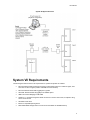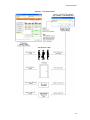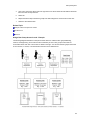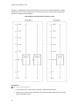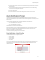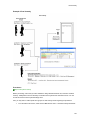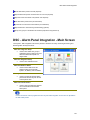
1
System VII User Guide v7.0.21 Table of Contents Keyscan System VII ........................................................................................................................................ 1 Press F1 for Help ...................................................................................................................................... 1 Introduction ..................................................................................................................................................... 2 What is Access Control ............................................................................................................................. 2 Access Control Features and Components ............................................................................................... 2 System VII Requirements .......................................................................................................................... 3 System VII Registration ............................................................................................................................. 4 System VII Client Main Screen .................................................................................................................. 6 Software Version and License Agreement ................................................................................................ 7 What's New ............................................................................................................................................... 7 What's New - Previous Versions ............................................................................................................... 8 System VII Function Keys ........................................................................................................................10 About the System VII Help .......................................................................................................................12 Setup the System...........................................................................................................................................13 Site Setup Wizard.....................................................................................................................................13 Manual Setup ...........................................................................................................................................13 Press F1 for Help .....................................................................................................................................13 Site Setup Wizard.....................................................................................................................................14 Log On .....................................................................................................................................................14 Site Setup.................................................................................................................................................15 Site Information ........................................................................................................................................16 Site Unit Setup .........................................................................................................................................21 Site Contacts Information .........................................................................................................................31 Schedule a Remote Modem Connection ..................................................................................................31 SMTP Email Settings ...............................................................................................................................33 Door Time Zones......................................................................................................................................33 Door Setup ...............................................................................................................................................41 Set Door and Reader Parameters ............................................................................................................42 Assign Time Zones to Doors ....................................................................................................................48 First Person In ..........................................................................................................................................49 Set Auxiliary Output Names & Auxiliary Output Status.............................................................................52 Set Auxiliary/Supervised Input Names-Output Assignment......................................................................53 Setup IOCB1616 Parameters ...................................................................................................................53 Assign Time Zones to Auxiliary Outputs...................................................................................................57 Assign Time Zones to Auxiliary Inputs .....................................................................................................57 Assign Time Zones to Supervised Inputs .................................................................................................61 Assign Time Zones to Readers/Keypads .................................................................................................62 Set Alarm Response Instructions/Alarm Graphic Locations .....................................................................63 Door Group Access Levels .......................................................................................................................64 Elevator Setup ..........................................................................................................................................66 Elevator Group Names .............................................................................................................................67 Set Elevator Bank Names ........................................................................................................................67 Set Elevator Names and Floor Hold Times ..............................................................................................71 ii Table of Contents Assign Elevators to Elevator Banks..........................................................................................................71 Set Elevator Floor Names ........................................................................................................................72 Set Elevator Banks to Time Zones ...........................................................................................................72 Assign Time Zones to Elevator Readers/Keypads ...................................................................................74 Set Elevator Time Zones to Automatically Lock/Unlock Floor Buttons .....................................................76 Elevator Group Access Levels .................................................................................................................77 Setup Holidays .........................................................................................................................................78 Assign Dates to Holiday 1, Holiday 2, or Holiday 3 ..................................................................................79 Setup Daylight Savings ............................................................................................................................82 Setup Cardholder Records .......................................................................................................................83 Complete Card Information and Access Levels .......................................................................................84 Signature Capture ....................................................................................................................................93 Create System Users ...............................................................................................................................93 System User Account Types ....................................................................................................................96 Setup Email for Alarm Notification ..........................................................................................................100 Schedule Automatic Database Backups ................................................................................................103 Database Location .................................................................................................................................106 Setup Communication Service ...............................................................................................................106 Upload Access Control Units..................................................................................................................111 Operate the System .....................................................................................................................................113 Alarm Monitoring ....................................................................................................................................113 Alarm Response Comments ..................................................................................................................114 Alarm Listings .........................................................................................................................................115 Alarm Notification Prompt.......................................................................................................................117 Alarm Types ...........................................................................................................................................118 Cardholders............................................................................................................................................120 Add a Cardholder ...................................................................................................................................120 Add a Block of Cards..............................................................................................................................120 Card Enrollment Feature ........................................................................................................................121 Searching for Cardholders .....................................................................................................................122 Cardholder Email Notification .................................................................................................................126 Edit/Delete Cardholders .........................................................................................................................127 Archiving/Unarchiving Cardholder Records............................................................................................128 Copy Card Records to Other Sites .........................................................................................................130 Replace Lost or Stolen Card ..................................................................................................................131 Create a Temporary Card ......................................................................................................................132 Find Cards with "Not Used Since" Feature .............................................................................................133 Print Cardholder Records .......................................................................................................................133 Print Photo Badges ................................................................................................................................134 Magnetic Stripe Encoding for MR-10 & MR-20 Readers ........................................................................135 Export Records in PDF Format ..............................................................................................................139 Import/Export Cardholder Information ....................................................................................................139 Reports - Access Levels.........................................................................................................................145 Communication Requests ......................................................................................................................147 Door Status/Manually Lock/Unlock Doors ..............................................................................................148 Keyscan Admin User Account ................................................................................................................151 Log On/Passwords .................................................................................................................................152 Database Options...................................................................................................................................154 iii System VII User Guide v7.0.21 Site Contacts ..........................................................................................................................................160 System Users .........................................................................................................................................161 Transaction Reports ...............................................................................................................................164 Display On-line Transactions .................................................................................................................173 Utilities....................................................................................................................................................175 Email System Maintenance ....................................................................................................................192 System VII Data Management .....................................................................................................................195 Database Maintenance Options .............................................................................................................197 System Reports ...........................................................................................................................................203 System Time/Date Management..................................................................................................................205 PC Clock ................................................................................................................................................205 Synchronize the ACU Clocks with the PC Clock ....................................................................................205 Geographic Time Zones .........................................................................................................................206 CCTV ...........................................................................................................................................................210 Setting Up CCTV ....................................................................................................................................210 CCTV Type Setup ..................................................................................................................................211 CCTV Command Setup..........................................................................................................................213 Show Live Video ....................................................................................................................................214 CCTV Action Setup and Email Notification.............................................................................................215 Operate the Video Control Panel ...........................................................................................................217 Present3.......................................................................................................................................................220 Present3 Modes .....................................................................................................................................220 Using Present3 .......................................................................................................................................227 Setup Present3 ......................................................................................................................................228 Lockdown .....................................................................................................................................................231 Lockdown - Doors/Elevator Floors .........................................................................................................231 Dual Custody ...............................................................................................................................................235 "Dual Custody" Reader Mode ................................................................................................................235 DSC Alarm Panel Integration .......................................................................................................................240 Introduction ............................................................................................................................................240 DSC - Alarm Panel Integration - Main Screen ........................................................................................241 DSC Alarm Panel Setup .........................................................................................................................242 DSC Alarm Panel Monitoring .................................................................................................................253 Keyscan Reporting Application ....................................................................................................................256 I/O Management ..........................................................................................................................................261 IOCB1616 Setup ..........................................................................................................................................262 Introduction ............................................................................................................................................262 IOCB1616 Operating Modes ..................................................................................................................263 And - Or Conditions / Timers / Time Zones ............................................................................................264 Example Applications .............................................................................................................................265 Setup IOCB1616 Parameters .................................................................................................................266 Glossary .......................................................................................................................................................270 iv Table of Contents Index ............................................................................................................................................................273 v Keyscan System VII Keyscan's System VII is the multi-dimensional software application that operates your access control system. It has been designed to give you complete and precise control over which individuals are permitted to enter specific doors or elevators at specific times on specific days. System VII keeps you informed of all site activity and alarm conditions. And, with its self-contained, internal database, System VII lets you keep detailed cardholder records and allows you to produce extensive, management reports and audits. Press F1 for Help System VII includes comprehensive, context-sensitive, on-line help. No matter where you are in the System VII software, pressing the F1 key opens the help for the interface screen that you're currently viewing. It explains the purpose of the screen and the steps to complete it. Help is always available when you're not sure how to do something. For a new installation, we suggest that first you review the topics under Introduction. When you're ready to start inputting data, follow the topics listed in Set Up the System which takes you through the necessary procedures to create a site and make it operational. System VII with Multiple Monitoring Capabilities 1 Introduction What is Access Control Electronic access control is based primarily on three Ws – WHO, WHERE, and WHEN. Bearing this in mind, an electronic access control system regulates who may access specific doors or other types of entry points, such as parking gates, or elevators at specified times. Authorized individuals are recognized by a "credential", which could be a card, token, fingerprint, or personal identification number. Acting as a sort of passport, each credential has a unique marker for individual identity. To gain access at a controlled door or entry point, the credential is presented at a reader. Like an invisible sentry, the access control system grants access or denies access based on programmed settings for the credential. Called a "transaction", each instance of attempted access, whether access is granted or denied, is recorded to a dedicated access control database. This database provides a source of records for auditing site activity and security information. Access Control Features and Components An access control system provides complete control and management of a building or site. controls door, elevator, parking lot, or garage access operates 24 hours a day, 7 days a week, 12 months of the year specifies access conditions for each individual at every door monitors access points for alarms integrates with other building systems connects to modems or networks for multiple building control reports site activity for complete security management auditing The access control system consists of the following components that work together giving you complete security and access control management: System VII software personal computer proximity cards or other forms of credentials card readers and/or keypads door locking hardware access control units (ACU) alarm monitoring 2 Introduction System VII System Overview System VII Requirements The following list outlines minimum PC requirements to operate the System VII software: Recommended Central Processing Unit (CPU): Intel Pentium Dual Core 2.2 GHz or higher; Intel Core Duo 2.6 GHz or higher (Celeron and AMD not recommended) Recommended minimum RAM: 2 gigabytes or greater Hard Disk: Recommended 100 gigabytes of available space USB Port for Photo Badging or USB-CAM COM Port - 1 required if using direct serial connection to access control units; 2 required if using CCTV control as well CD-ROM or DVD drive Mouse or compatible pointing device Removable Media Storage Device such as CD or DVD Writer for database backup 3 System VII User Guide v7.0.21 Network Interface Card (NIC) with TCP/IP protocol, a valid, active IP address (PC with System VII database - SQL Server 2005 Express - must be assigned a static IP address) and file & printer sharing for Microsoft networks Graphic Card supporting 1024 x 768 or higher screen resolution Operating Systems: Windows 8* (32 bit or 64 bit) – Professional & Enterprise versions Windows 2012 Server* (64 bit / graphical user interface enabled) – Standard version Windows 2008 Server Windows 7 – Professional, Enterprise & Ultimate versions Vista Business Windows 2003 Server Microsoft Internet Explorer 6.0 SP1 or later Microsoft .NET Framework 3.5** required for Windows 8 or Windows 2012 Server Microsoft .NET 2.0 Framework required for all other supported operating systems Virtual Server*** (Communication as a service recommended for virtual server configurations) Keyscan's System VII software is a 32-bit application. * On installation of Keyscan database (SQL Server 2005 Express) user may be prompted with Program Compatibility Assistant. To clear message and continue installation, user selects Don’t show this message box again option, and then selects Run the program without getting help command. ** .NET Framework 3.5 (includes versions 2.0 and 3.0) must be enabled from the Control Panel > Programs & Features > Windows Features screen prior to installation of Keyscan software. *** Supports virtual machine server topology providing that all licensed and required Keyscan software applications are allocated sufficient server resources for proper system performance and that the VM software/server is supported by qualified IT personnel. Keyscan has tested OS compatibility with System VII but makes no guarantee for OS compatibility with third party software applications or third party drivers. For sites with large cardholder populations and high volumes of transactions, we strongly recommend that you install the Database Module (SQL Server 2005 Express) on a dedicated PC. Faster processors and higher RAM provide better system performance. To confirm that your PC meets the recommended requirements, you can view the PC's system information by selecting Start > (All) Programs > Accessories > System Tools > System Information. System VII does not support touch screen panels. For systems that exceed 12 access control units and/or 100 readers, you may request Keyscan’s System Architecture White Paper for additional specifications and recommended communication configurations to derive optimum system performance. Requirements and specifications are subject to change without notice. System VII Registration You must register your System VII software application to be an authorized user. Only registered users are eligible for Keyscan technical support. You can register using either of the following methods: 4 Introduction telephone on-line The procedures for each registration method are outlined below. Keyscan offers a trial period of 30 days to review the software application. During the 30 days you are free to try the product, however, you are not eligible for any technical support. When the 30 days have ended, the application no longer functions. If you wish to register later, complete the Company Information and the Dealer Information on the Software Registration form. The top 4 captions under the Company Information and the Dealer Information are required fields. Click on the Register Software Later button. Register by Phone Complete the Company Information and the Dealer Information on the Software Registration form. The top 4 captions under both the Company Information and the Dealer Information are required fields. Your software package includes a card with a registration serial number for each software module that you purchased. Enter the serial numbers in the applicable Serial Number text boxes on the Keyscan System VII Registration form. Have your Machine Key Serial Number, the registration software serial numbers, and your company and dealer information available and call one of the Keyscan numbers listed below. A Keyscan representative will provide you with a corresponding Unlock Serial Number for each purchased module to complete your registration. Telephone Numbers Hours Days Canada/USA -Toll Free 1-888539-7226 9:00 A.M. – 5:00 P.M. Eastern Time Monday – Friday Outside Canada/USA 905-4307226 Enter the applicable Unlock Serial Number for each module purchased. Select the Register Software button. Register On-line The PC you are registering from requires a connection to the Internet. Complete the Company Information and the Dealer Information on the Software Registration form. The top 4 captions under the Company Information and the Dealer Information are required fields. Your software package includes a card with a registration serial number for each software module that you purchased. Enter the serial numbers in the applicable Serial Number text boxes on the Keyscan System VII Registration form. Record the Machine Key Serial Number. This is a required entry when you register on-line. 5 System VII User Guide v7.0.21 Select the Register Software Online button. Follow the on-screen prompts and complete all required fields. System VII Client Main Screen 1-Software Menus Use the pull down menus to access all the forms in the Client software application to create, edit, and delete site information. Press the F1 key on any screen in System VII for help. 2 Quick Buttons Quick buttons are convenient shortcuts to commonly used functions. To access a Quick Button, click on the caption directly below the icon. All Quick Buttons displayed on the main screen can also be accessed from the Quick Buttons menu. 6 Cardholder Database - Provides quick access to perform all tasks associated with cardholders. Time Zones/Schedules - Provides quick access to add, edit, or delete time zones, schedules or holiday schedules for doors or elevator banks. Door Lock Unlock Status - Provides direct access to manually lock or unlock doors. Group Access Levels - Provides quick access to edit either door or elevator group access levels. Each door or elevator group is assigned an access level – no access, 24 hour access, or an access period based on a time zone. Display On-line Transactions - Provides direct access to view and sort site transactions. Transaction Reports - Provides direct access to run user-specified transaction reports on site activity. Alarm Listings - Provides direct access to view new or pending alarms or find alarms by a date range. Update Changes - Accesses the Panel Updates form to upload data to the access control units. Introduction System VII Client Main Screen Software Version and License Agreement The System VII Client version and current license agreement are specified on the About form, which is accessed from the Help menu. System Information can be displayed by clicking on the System Info… button. To close the window, click on the OK button. What's New Keyscan is constantly striving to refine and improve its software and hardware products to furnish you with the best features and tools for effective access control management. System VII - Version 7.0.21 Here's what Keyscan has added and enhanced to the newest version of System VII: New Features Added message box warning (EOL) when adding/editing a modem connected ACU Added code to check and ask for Scanner Model Type in Visitor Software. This is setup/saved via the Maintenance Options window in the Visitor Management software Added code to handle trouble short and trouble open on doors in Active Mapping 7 System VII User Guide v7.0.21 Enhancements Changed default setting for Reader LED checkbox to be checked for PC1097 boards Changed wording on Avigilon NVR live camera message Changed message to remove wording about NETCOM on CA150 Rev. B board programming in NETCOM Programming Tool Changed default baud rate on CA150 Rev. B boards to 115200 and also removed unsupported baud rates for CA150 Rev. B board Changed Web Client - Transaction Report Options screen, the ability to “Include Card Field Options” are hidden based on the users permissions Corrected issue to handle certain email transactions when software does not have DSC license registered Corrected issue with setting email notifications Corrected display issue with option fields in the online transaction window Corrected issue with SDK and the KeyscanViewUserSiteIDs function Corrected display label of next time run value in Auto Import What's New - Previous Versions System VII - Version 7.0.20 8 Added Refresh History button to Visitor Information screen for improved loading time Added support for SDK to retrieve if complex passwords enabled Added feature to turn ON or OFF auto generation of PINs when adding new cards in Web Client Added support for CA150 units that have the XPico chip and DIP switches via NETCOM Programming Tool Added support for new button for CA150 Rev. B product Added support for showing last transaction on Door Status screen via an enabling feature Added new feature - Assign Time Zones to Elevator Reader/Keypad Operation (requires firmware update) Enhanced Communication Manager when running in non daylight savings area and panels are located in other time zones that follow daylight savings Enhanced support to disable the record button when connecting to a DVR3 unit Enhanced support to prevent attempted saves when no video has been recorded Enhanced support for handling PINs when the user does not have viewing authority - PIN is preserved when editing via the Web Client Enhanced support timer to 5 minutes to check for files via Auto Import Enhanced support for Arizona & Saskatchewan displaying online transactions Enhanced support when arming Power Series DSC partition with message box prompting user to arm with code or arm without code. Default is without code Corrected issue with Clock Sync when Time Zone of ACU does not match Time Zone of Comms Manager Corrected issue with Mapping to handle when door first starts as Auto Locked, then card pressed and door graphic would not close Corrected rounding off issue with Cumulative Hours Report calculations Introduction Corrected issue when trying to run report and selecting Dual Custody transactions without DSC registered System VII - Version 7.0.19 Added Support for New ACU boards that have DIP switch settings and software selectable options Added Support for New NETCOM boards that have programming option onboard Added Support for New NETCOM firmware 6.9.0.x versions Added Support for to allow for programming of NETCOM2B, NETCOM2 or NETCOM2P via network connections that are pre-defined IP addresses Added Support for NETCOM boards to be programmed for Discovery and added new option to Discovery NETCOM boards Added Support for Optional Fields being displayed in Online Transaction window. Added Support for Saving Reports to be run via the Email Reporting Service Added Support for Avigilon NVR Integration Added Support for new function in SDK - KeyscanBatchEmailCardFunction - which will allow batch email messages from cards that have a valid email address in the email address field of the card holder Added Support for 3 Online Transaction Windows in Web Client Added Support for New Service - Email Reporting Service Enhanced Support for Arizona Time Zone handling Enhanced Support for KDVR Viewer Enhanced Support for Web Client - Online Transactions now allows the customer to select a geographical time zone to watch Enhanced Support for Display Only Unique Card Holders option and export option Enhanced Support for Elevators - Increased the number of Elevators that can be assigned to Elevator Tables to 40 Enhanced Support for Temporary Card Holders when selecting Temporary Date via the Calendar Enhanced Support for logging of purge data, to include a single log entry for each site selected during the purge Enhanced Support for Clear Unlinked Photos - Removed the Clear Unlinked Photos option from Client software and moved it to Patch Process Tool Enhanced Support for overall application performance Corrected issue when collecting card transactions with certain internal card IDs in Communications Manager Corrected issue with Display Only Unique Card Holder when using Extended Card option in Client Software Corrected issue when logging into Web Client with complex passwords Corrected issue where Web Client card import would not import last field System VII - Version 7.0.18 Added support for global lockdown feature Added support for 37bit H10304 format cards Added support for email notification from the Search Access Card Holder screen Enhanced Client software - Added new authority level for global lockdown feature Enhanced Client software - Added new authority level for Copy Card To Another Site Enhanced Client software - Added support to display card batch & card number for extended H10304 cards 9 System VII User Guide v7.0.21 Enhanced Client software - Changed default length of corporate ID to 4 Enhanced Client software - General interface enhancements Enhanced DSC Communication - Included geographical time zone when setting Enhanced Web Client - Added support for extended cards and corporate IDs Enhanced Web Client - Transaction reports Enhanced Web Client - Importing of cards and temporary valid to and from dates Enhanced Visitor - Changed loading of access card drop down to include only cards that have been assigned to a visitor record System VII Function Keys The following list outlines shortcuts to access specific screens using the functions keys at the top of the keyboard: F1 - On-line Help Press the F1 key to open the System VII help. The help is context sensitive and opens on the topic relevant to the interface screen you are viewing. F2 - Switch Site Listing To change sites from the main screen, press the F2 key to open the Switch Site Selection screen. Select the desired site in the table, and click on OK. F3 - Communication Status From the Client main screen, press the F3 key to review the current communication status of the control units at the sites you are permitted to view. For Reverse Network sites, the Communication Status screen has a disconnect function for momentarily suspending communication. F4 - Panel Updates When a panel is selected in the Panel Updates screen, pressing F4 opens a dialog box listing the panel serial number and the model type. F5 - Refresh When either the main, alarm, or transaction screens are open, pressing F5 updates the screen. F6 - Time Zone Status Pressing F6 from the main screen opens the Time Zone Status screen. 10 Introduction F7 - Keyscan System Log Entry When the F7 key is pressed from the main screen, the Door Lock/Unlock Status screen, or the Manual Output Control screen, the Keyscan System Log Entry text box opens. This can be used to provide an explanation in the system log why any actions were taken such as manually unlocking a door or toggling the state of an auxiliary output and so on. F8 - Alarm Monitoring Window - Main Screen When the System VII Client is the active window, pressing F8 brings the Alarm Monitoring window to the front if it was behind the Client main screen. F8 - Cardholder Photo Search - Card Holder Screen When the Card Holder screen is open and the card record does not have a photo attached, pressing F8 instructs the Keyscan software to search for a cardholder photo assigned to the same batch/card number at all other sites. If it’s found, the image is displayed in the cardholder photo box. Save the record to retain the image. F9 - Site Information Search Shortcut Pressing the F9 key from the Client main screen opens the Site Information Search screen. F10 - Site Unit Setup Shortcut Pressing the F10 key from the Client main screen opens the Site Unit Setup screen. F11 - System Tools / Utilities Pressing the F11 key opens the System Tools / Utilities menu on the About screen. F12 - Language Selection Pressing the F12 key from the main screen opens the Change Language dialogue box. Select Yes to change the interface. Select No to scroll to the next interface language option. The following languages can be selected: English French Spanish Esc Key During a panel upload, pressing the Esc key aborts the upload. The upload continues until all data from the current field has been sent to the panel to maintain continuity between the database and panels before it aborts. 11 System VII User Guide v7.0.21 About the System VII Help The System VII on-line help can be accessed in two ways: from the Help menu on the main screen pressing the F1 key from anywhere in the System VII software The help has two window panes: Left Pane - Contents/Index/Search for navigating the help Right Pane - Topic information, procedures, and related topic links Contents/Index/Search Double click on a closed book or click the + to the left to open a book and view related topics. Click on a topic to view the contents. Click on the Index tab and type a word or phrase in the text box and select the topic from the list. Important Information Indicates important information Procedures A green arrow indicates instructions, diagrams, or explanations. Click on the italicized green text to the right of the green arrow to open. To close, click on the italicized green text again. Related Topic Links 12 A blue arrow indicates to a related topic. a link to related topics. Click on the italicized & underlined blue text to go Setup the System After installing the System VII software, the next task is to set up your site. This involves entering data on the software screens that are accessed from the menus or the quick buttons on the Client's main screen. The configuration of your site will determine which screens you will have to complete. In some cases menus will be dimmed and unavailable or screens will be blank depending on the types of controllers configured on the Site Unit Setup screen. As an example, if your site does not have elevators, the Elevator Controllers menu is not accessible and you do not have to input any elevator data. In some cases, you may require the assistance of your dealer/installer to configure the access control units, as well as any inputs and outputs connected to external devices. Site Setup Wizard The System VII software includes a Setup Wizard which automatically opens a predetermined set of software screens to get your system up and running. Complete the screens as they are presented, select the Save button, and the next screen opens automatically. Manual Setup If you elect to setup the system manually, following the order of the books in the left pane under Setup the System will take you through all the screens necessary to get your site functional. Bypass the screens that don't apply to your site configuration. Press F1 for Help If you need assistance at any time, press the F1 key for help. The help opens from anywhere in the System VII software. Until the PC you are using to setup the System VII software has a communication link with the access control panels, you will have a Communication Status FAILED message on the main screen. This is normal as the software has been designed to advise you whenever it can't "talk" to the access control units. You will not be able to open some of the Door Maintenance forms nor Upload the Panels however until the access control units are operating and communicating with the PC. Related Topic Site Setup Wizard 13 System VII User Guide v7.0.21 Site Setup Wizard The Site Setup Wizard is an on-line aid that guides you through the steps to setup your site. When you start the Site Setup Wizard, it automatically opens the screens for each step in successive order. Just enter the required information and save your data as you progress through each screen. The Site Setup Wizard does not allow you to deviate from the order of the screens as they are presented. Do not open other screens from within the screen you are completing, otherwise the Site Setup Wizard closes. The Keyscan System VII Software Installation Guide has a section entitled Setup a Site near the back that has an outline on how to use the Site Wizard. Procedure To Open the Site Setup Wizard, select the System Settings menu > Site Wizard > Start Wizard button. Log On When you open the Client application or switch to another site, you are prompted to specify the following information in the Log On dialog box: Specify the name of the site you are logging on (if other than the site listed in the Site Name box) Select a language (N/A) Enter your user name Enter your password You will note that any time a system user account has been assigned with the Master Login designation; it is listed in the Site Name field. For more information on Master Login, see Setup System Users under Setting Up the System in the Contents window. Procedures Steps to Log On 1. 2. If you are logging on for the first time or you have not created a specific user account, type the following in the corresponding text boxes : User Name: Keyscan Password: KEYSCAN (Must be in entered in upper case.) Click on the OK button Each subsequent time you open the Client application, you must log on by specifying the site name, and enter your User Name and Password, which will be based on what was entered in your user account in the System User Information form. Until you create user accounts for system administrators, the above applies to logging on to the Client and the optional Photo Badge Template Editor. Related Topics Log On to Another Site 14 Setup the System Passwords Site Setup The Site Setup screens identify the site, specify the types of access control units installed, set communication criteria, and list the names of persons to be notified in an emergency. Site Setup consists of the following screens: Site Information Site Unit Setup Contact Information Schedule Remote Modem Connection (optional if using a dial-up modem) SMTP Email Settings (required if using email alarm notification) Before beginning to create your new site, you need to know the access control unit (ACU) serial numbers, unit types, and unit passwords. The ACU serial number and unit type are listed on the packing slip or they can be found on the main control board inside the ACU panel. The default password for all Keyscan ACUs is KEYSCAN. This information has to be entered in the Site Unit Setup screen. Print Site Setup As a safeguard to protect your site data, after you have completed the site setup screens, it is strongly recommended that you print a hard copy of the site information by selecting the Print Site Setup button on the Site Information Search screen and store the site records in a safe place. You should always print a new copy whenever site information is added or changed. Site Information Search When you access Site Setup from the System Settings menu, the first screen to open is the Site Information Search screen. Whether adding a new site or amending information on an existing site, the Site Information Search screen allows you to do the following tasks: search for sites list all sites create a new site access a specific site to edit site information Print Panel Summary The Print Panel Summary function provides a list of key access control unit information which also can be printed for a hardcopy record: Unit ID 15 System VII User Guide v7.0.21 Serial Number Type (controller model) Communications Settings Host/Remote modem telephone numbers (if applicable) Print Site Setup The Print Site Summary function is more comprehensive than the Print Panel Summary function giving you the following range of selectable site categories to include. This summary can also be printed for a hardcopy record. Site Contact Information Panel Setup System User Information Holiday Details Daylight Savings Setup Door Time Zones Group Access Levels Input Names & Alarm Responses Reader Information & Door Timer Setup Auxiliary Output Names Assigned Time Zones to Inputs, Reader/Keypads Elevator Controllers Procedures To create a new site, select the Add Site button to open the Site Setup screens. To locate, verify, or update information about an existing site, click on the Find Sites button to list all sites or specify specific criteria in the field search text boxes at the top to narrow your search, then click on the Find Sites button. To open an existing site, double click on the site name in the table. To run a summary, select either the Print Panel Summary or Print Site Setup buttons. When the Print Site Setup button is selected, all site categories are pre-selected. To omit categories, de-select the category by clicking in the box to the left. The box no longer has a check mark. Site Information The purpose of the Site Information screen is to identify the location of the site. This includes a site ID descriptor, the site name, address and telephone number. You must also specify whether you are creating a host or remote site and in the case of a remote site, specify the data collection format that is employed to transfer data from the access control units back to the host site database. 16 Setup the System Site ID Naming Structure If you plan on creating multiple sites, Keyscan suggests using a consistent format when naming the Site ID. This makes it easier to organize and locate sites on the Site Information Search screen and a consistent format helps system users log on to the desired site. The following illustrates an example of creating a consistent Site ID format. Please remember this is only an example of a consistent format. Naming Site IDs is arbitrary and should be geared to what makes sense for you. You can use up to 8 alpha & numeric characters for the Site ID. Example SITE0001 SITE0002 SITE0003 Card Formats Keyscan access control systems support multiple card formats as outlined below: 3 Digit Batch Code / 5 Digit Card Format Large Card Formats HID Corporate 1000 Card Format (35 bit) HID Corporate 1000 Card Format (37 bit) It is important that you know the card format you are using so that you make the correct settings on the Site Information screen. The Keyscan Client handles each card format in a different manner. This directly affects how cards are entered in the Cardholder Information screen. Please be sure that you know which card format you use before you complete the Site Information screen. 3 Digit Batch Code / 5 Digit Card Format If you use cards with a 3 digit batch code and a 5 digit card number, do not enable the settings under Card Format Options. Generally, this is the most common type of card format. Large Card Formats If you use a large card format, ensure that you enable Extended Card Number Support in Card Format Options as shown below. Large card formats can include University 1000, FIPS/TWIC, Mifare CSN 32 & 40, and other 3rd party OEM proprietary card formats. HID Corporate 1000 Card Format (35-bits) If you use HID's Corporate 1000 cards, you must enable Extended Card Number Support and enter the hex value of your Corporate ID number under the Card Format Options in the Site Information screen. You can use the Windows calculator (scientific mode) to convert the corporate ID number to a hex value. If you use or plan to use the HID Corporate 1000 card format with multiple Corporate ID numbers for the same site, do not enter a hex value in the Corporate ID (Hex) text box. Leave it blank. Once you enter a hex value in this field you will be restricted to using 1 Corporate ID for the site. HID H10304 Extended Format (37-Bits) If using HID's H10304 37-bit format, you must enable the Extended Card Number Format and select 37 bit H10304 from the Extended Card Type drop down list. The facility code may be entered in the Corporate ID 17 System VII User Guide v7.0.21 (Hex) field. If you have multiple facility codes for your HID H10304 format cards, enable only the Extended Card Number Support option. Leave the Corporate ID (Hex) and the Extended Card Type fields blank. If you are not sure whether you use a large card format, contact your dealer or distributor to verify the card format. Do not continue to setup your site until you have verified your card format. If you do not use a Large Card Format or HID Corporate 1000 formats, do not set either of these fields. Once you enable Card Format Options and have saved cardholder records, you cannot revert back to the 3 digit batch code/5 digit card number format unless you delete those cardholder records. Password Expiry Option As an option, you can specify a password expiry period. All system users must create a new password after the expiry period occurs. The Password Expiry option is per site. Complex Passwords For creating a higher and more sophisticated level of system user passwords, you can enable the Passwords must meet complexity requirements field. the Keyscan system user account requires a Master Login Account designation to open and enable this field. This field is normally hidden from view on the Site Information screen until the F3 key is pressed when the system user account has a Master Login Account designation. If complex passwords are put in effect, all passwords must conform to the following conventions: contain at least 1 upper case alpha character contain at least 1 lower case alpha character contain at least 1 numeric character from 0 to 9 contain at least 1 of the following special characters space contain a minimum of 6 characters in the password ~ ! @ # $ % ^ & * ( ) or a single The complex password is assigned per site. This is not recommended unless you are an advanced user. Cardholder Folder Location The Site Information screen has a Cardholder Folder Location field. If you have Keyscan's optional System VII Photo Badging module, you can use this field to specify an alternate folder location for your cardholder images. 18 If you leave this field blank, cardholder images are saved in the Keyscan database. If you specify a Cardholder Photo location, cardholder images are saved in the Keyscan database as well as the specified folder location. Setup the System Disable Time Zone Synchronizing When a time zone is amended, the access control system doesn’t effect the change until the next ON or OFF cycle when this option is engaged. Access Denied Warning Function The Access Denied Warning function is designed to report via an email when cards have been presented at readers where the cardholders do not have permission to enter. The access denied warning can be adjusted from 1 to 10 access denied violations before the email is sent. By default this function is disabled until the number of card violations is specified. You must have the SMTP Email Setup configured, which is accessed from the Site Information screen, for the Access Denied Warning function to operate. This only applies to a card that has been assigned to a cardholder record in the Keyscan database. Example As an example, if the access denied warning field is set to 3 the following would result: If a card is presented 3 times at any reader within the site where access is not permitted, an email is sent to the specified email address after the 3rd card presentation produced a 3rd access denied violation. The email recipient receives a Keyscan Access Denied Threshold Warning email listing the transaction details of the card/cardholder violation. If the cardholder record has a photo, the photo is included with the email as an attachment. Card Assignment Notice / Email Address This function sends a notice via email if and when the number of cardholder records added to the database exceeds the threshold value entered in the Card Assignment Notice field. If and when the cardholder threshold is crossed, an email is issued at 12:00 A.M. each day thereafter until the Card Assignment Notice value is changed or disabled. Example If the value in the Card Assignment Notice were set to 100, whenever the 101st cardholder record was added to the database, an email would be sent at 12:00 A.M. with the message Card Assignment Value Exceeded. If using this feature, enter the email address of the person who is to receive the notice in the Email Address text box to the immediate right of the Card Assignment Notice field. The Card Assignment Notice function requires a main communication manager running within the Keyscan database. You must have the SMTP Email Setup configured, which is accessed from the Site Information screen, for the Card Assignment Notice function to operate. To disable the Card Assignment Notice function, leave the field blank or delete any previous value if one was entered. Require Person Visiting in Visitor Software When this option is selected, a system user logged on to the optional Visitor Management software must specify whom the visitor is meeting by selecting a contact from the Person Visiting field. Without assigning a contact in this field, the system user is prompted to select a Person Visiting. The scheduled visit cannot be saved until this field has been assigned a contact name. 19 System VII User Guide v7.0.21 Procedures Steps to Complete the Site Information Screen 1. From the main screen, select System Settings > Site Setup > Site Information Search. Click on the Add New button. 2. Click in the Site ID text box and enter an ID name. The maximum is 8 characters. The purpose of a Site ID is to identify the location so that other individuals operating or monitoring the system can determine the source of where an alarm occurs. This is especially important where multiple sites are going to exist. 3. Click in the Site Name text box and enter the name of the site. 4. Complete the remaining site information from Site Location to Fax Number, whichever fields are applicable. 5. If applicable, enter any special comments in the Site Comments text box. 6. Specify a Card Holder Folder Location if you have the optional System VII Photo Badging module and you want your cardholder images to reside in an alternative folder. All cardholder photos are saved in the Keyscan System VII database as well. 7. To disable time zone synchronizing, click in the box to the left. The box has a check mark when this option is engaged. If you amend times zones frequently this option is recommended, otherwise you can leave it off. 8. If you use a Large Card Format or HID Corporate 1000 format, click in the box to the left of Extended Card Number Support. The box has a check mark when enabled. Do not activate any fields in the Card Format Options if you do not use a Large Card Format or HID Corporate 1000 Format. 9. If you use HID Corporate 1000 format, enter the corporate hex value in the Corporate ID (Hex) box. (If you plan on using more than 1 Corporate ID for this site, do not enter a hex value.) You can use the Windows calculator to convert the corporate number to a hex value. Set the calculator on Scientific. Ensure Dec is selected. Enter the corporate ID number by clicking on the calculator's numeric buttons. Click in the hex radio button. The Hex value is calculated. This is the value you enter in step 6. 10. If applicable, click on the down arrow to the right of System Logging Level and select a level. The default is Full Logging Level which lists all the user's activity in the System Log. To retain fewer details in the System Log, select a level between Level 1 and Level 4. Level 4 retains the least System Log details 11. To enforce a password expiration period for all site system users, click in the box to the left of Password Expiry Enabled. The box has a check mark when enabled. If you have selected this option go to step 12. If you are not invoking an expiry period for passwords, go to step 14. 12. Click on the down arrow to the left of Password Expiry and select one of the password expiry time periods. At the end of the period the system user will be prompted to enter a new password to log on to a Keyscan software module. The system user cannot use the same password back-to-back. 13. To invoke complex passwords for this site, press F3 on the keyboard. Click inside the box to the left of Passwords must meet complexity requirements. When enabled the box has a check mark. 14. If you have the optional Visitor Management software and want to enforce tracking who each visitor meets, click in the box to the left of the Require Person Visiting in Visitor Software to enable this function. The box has a check mark when enabled. 15. If you are going to use the Access Denied Warning function, click the down arrow below and to the right of Access Denied Warning and select a threshold value from 1 to 10 in the list. 20 Setup the System 16. In the text field below Email Address, enter the email address of the recipient who is to receive the Keyscan Access Denied Threshold Warnings. 17. If using Card Assignment Notice, enter a value in the text box immediately below the heading. 18. To the immediate right of Card Assignment Notice and under the Email Address heading, enter the email address of the recipient who is to receive the notice. 19. If the site has any modem connections and you do not want the Host site to automatically dial out to the remote site/panels and perform an upload whenever cardholder, time zone, holidays, daylight savings, or access level data has been added or revised, select Disable Auto Updates by clicking in the box to the left. 20. To assign the site you are creating as the default site, select the Default Site check box to activate the field. When you log on, the Default Site is automatically listed in the Site ID field on the Client Log On dialog box. 21. If there are no modem connections go to step 27. If you have modem connections but are creating a host site, leave the default setting at No Collection and go to step 26. If you are creating a remote site/panel with a modem connection go to step 21. 22. Specify one of the following Activity Collection options: Capacity Only – the host site is contacted when the remote site’s ACU memory reaches the specified percentage of its total capacity. Specify the percentage in the % of Capacity field. Time/Capacity – the host site is contacted when the remote site’s ACU memory reaches the specified % of its total capacity or at the specified time whichever event is first. Specify the percentage in the % of Capacity field and the time in the Time HH:MM fields. 23. If there is a time period when you do not want the remote site/panel modem connecting with the host site, select a time zone from the drop down list by clicking on the arrow to the right of Time Zone – Disable Dialing Period. The time zone selection is based on the remote panel's type – door or elevator. You may wish to create a specific door or elevator time zone for this function. For a new site, you will have to first create a time zone and return later to assign a disable dialing period. 24. To set the number of dial attempts in case the modem fails to make a connection on the first call, click on the down arrow to the right of Dial Attempts and select a number from the list. The range is 1 to 99. 25. To set the Delay Attempt Time, the period in minutes between dial out attempts, click on the down arrow to the right and select a number from the list. The range is 1 minute to 99 minutes. 26. In the Host Telephone Number enter the telephone number that the remote site/panel calls. 27. In the Access Control Unit Modem Initialization String, right click to open a drop down list and select the correct initialization string. If you are unsure of which string to select, consult your modem manufacturer’s literature. 28. Complete the other screens by clicking on the respective buttons, Site Unit Setup (required) and Site Contacts (optional), SMTP Email Setup (optional) and Schedule Remote Connections (optional). When you have completed the other screens, be sure to click on the Save & Exit button. Site Unit Setup Site Unit Setup is used to identify the access control units installed and set communication criteria. You may require the manufacturer’s literature that accompanied your modem or network card for communication settings. The baud rate specified on the Site Unit Setup screen for a serial connection must match the baud 21 System VII User Guide v7.0.21 rate jumper setting on the access control unit circuit board. You may have to consult with your dealer/installer. Unit ID Naming Structure When you are configuring access control units in the Site Unit Setup screen, Keyscan recommends using a consistent format to identify the panels in the Unit ID field. This makes it easier to organize and locate access control units on the Site Unit Information screen. A consistent format also helps system users identify the desired panel when performing Client administration tasks. The following illustrates an example of creating a consistent Unit ID format. Please remember this is only an example of a consistent format. Naming Unit IDs is arbitrary and should be geared to what makes sense for you. You can use up to 6 alpha & numeric characters for the Unit ID. Example of Door Control Units ACU001 ACU002 ACU003 Example of Elevator Control Units ECU001 ECU002 ECU003 Before beginning to complete the Site Unit Setup screen, you need to know the access control unit serial number, unit type, and unit password. The ACU serial number and unit type are listed on the packing slip or they can be found on the main control board inside the ACU panel. The default password for all Keyscan ACUs is KEYSCAN. If you are adding or re-configuring more than a single panel, be sure that you give each panel a unique description in the Unit ID field. These descriptions are user defined. Hardware Settings for DIP Switch (S2) Configured Control Board Only When a CA200, CA4000, CA8000, CA1000, CA2000, or CA256 series panel from the Unit Type (Series) drop down box is selected, the Hardware Settings – DIP Switch (S2) Configured Control Board Only dialog box opens. This dialog box only applies to setting hardware functions for PC1097 version or higher control boards with DIP switches as outlined below. 22 Reader Formats (formerly jumper J3) End-of-line supervision mode (formerly J18) Reader LED lock state (formerly J16) Temporary card countdown (formerly J16) Accessibility HC relay all cards enabled (formerly J16) Reader lockdown LED mode (formerly J18) Setup the System Do not select or enable any fields in the Hardware Settings – DIP Switch (S2) Configured Control Board Only dialog box unless you are adding a PC1097 version or later control board. Previous control board versions are distinguished by jumpers which regulate the above hardware functions. Reader Formats This sets the control board reader format. Reader formats apply to PROM version 4.03 or greater unless stated otherwise in the table. Keyscan does not recommend any 26-bit card formats. 26-bit cards and tags are not secure. Duplicate card numbers exist in this format so a facility is vulnerable to unauthorized access. See Waiver of Liability below. Also refer to Security Levels below for more about reader/card formats. All Keyscan control boards are factory defaulted on Keyscan's 36-bit Wiegand proprietary format. Advantage of Keyscan 36-bit Proprietary Wiegand Format Cards Keyscan’s 36-bit proprietary Wiegand format cards and tags, which include a manufacturer’s code, offer a high level of security. Keyscan tracks all its cards and tags. This ensures that no duplicate cards or tags are sold by Keyscan. When installing or upgrading a Keyscan access control system, we recommend our proprietary Keyscan 36-bit Wiegand format cards and tags, available in 125 kHz or 13.56 MHz formats, for a high level of security. Waiver of Liability Installing dealers should have an authorized end-user sign a waiver of liability before enabling 26-bit reader formats/cards. Keyscan has enclosed a Waiver of Liability click the link below Related Topics. Reader Security Levels The Reader Formats table below reviews not only supported reader formats, but also the security level of each format. Be aware that where Keyscan’s 36-bit proprietary cards share a combined reader format with other manufacturer’s cards, the other manufacturer’s card binary bits may be truncated to accommodate the joint format. This lessens the overall security, as not all bits are read. The reader formats in the table have been given one of following security ratings: High Medium Low Very Low Reader formats ranked with medium, low, and very low are NOT recommended. The ratings are based on whether a card’s binary bits are truncated and/or the cards are sold by other manufacturers, which Keyscan has no control over. Keyscan assumes no responsibility for liability for any card format. Reader Formats Ref # Reader Format Security Level Card Number Format A Keyscan 36-bit only High Standard B FIPS/TWIC – 75-bit output (48-bit FASC-N, 25-bit expiration date, 2 parity bits) High Extended Notes Legacy support only 23 System VII User Guide v7.0.21 C HID Corporate 1000 - 35-bit output Medium Extended D MIFARE – CSN 32-bit output Low Extended Only reads the card serial number sector E MIFARE – Reverse CSN 32bit output Low Extended Only reads the card serial number sector F MIFARE – 40-bit CSN (32-bit CSN, 8-bit Checksum) Low Extended Only reads the card serial number sector G 26 to 48 Pass-through Large Card Format Medium Low Extended H 26 to 48 Pass-through Large Card Format (with first and last parity bits dropped) Medium Low Extended I University 1000 - 56-bit Medium Extended Custom order only. Facility code required when ordering. J MIFARE Reverse 40-bit (32bits reverse CSN + 8-bits checksum = 40 bits Low Extended Only reads the card serial number sector K MLF Indala Format = 16039 Medium Extended Custom order only. Letter required from dealer. L FIPS/TWIC – 75-bit output (48-bit FASC-N, 25-bit expiration date, 2 parity bits) & Keyscan 36-bit High Extended Legacy support only M FIPS/TWIC – 75-bit output (48-bit FASC-N, 25-bit expiration date, 2 parity bits) & Keyscan 36-bit & Mifare – 40bit CSN (32-bit CSN, 8-bit Checksum) High Extended Legacy support only N 37-bit H10304 & Keyscan 36bit Medium Extended Reader PROM 4.04 or higher O 37-bit H10302 & 35-bit Corporate 1000 Medium Extended Reader PROM 4.04 or higher Reader formats Ref # 1 - 31 are NOT recommended. 1 Standard 26-bit & Keyscan 36bit Low Standard 2 Legacy Northern 34-bit, Standard 26-bit & Keyscan 36bit Low Standard 3 Corby 30-bit & Keyscan 36-bit Medium Standard 4 Kantech 32-bit & Keyscan 36bit Medium Standard 5 DSX 33-bit & Keyscan 36-bit Medium Standard 24 Setup the System 6 Intercon 32-bit & Keyscan 36bit Low Standard 7 Legacy Chubb 36-bit (5 & 6 digit cards) & Keyscan 36-bit Low Standard 8 Keyscan 36-bit with zero batch number Low Standard except Facility Code = 0 Enter 0 (zero) for the facility code in the Client software to ignore the FC output from the reading device. 9 Standard 26-bit & Keyscan 36bit Low Standard – except for 26bit cards Facility Code = 0 Enter 0 (zero) for the facility code in the Client software to ignore the FC output from the reading device. 10 Northern 34-bit & Keyscan 36bit Low Standard – except for 34bit cards Facility Code = 0 Enter 0 (zero) for the facility code in the Client software to ignore the FC output from the reading device. 11 Corby 30-bit & Keyscan 36-bit Low Standard except for 30bit cards Facility Code = 0 Enter 0 (zero) for the facility code in the Client software to ignore the FC output from the reading device. 12 Legacy GE 40-bit or CasiRusco Ex. Prox-Lite 941-W RDR Low Standard 13 Legacy (37-bit Corp H10302) & Keyscan 36-bit Low Standard 14 Legacy Keyscan England 36bit with no manufacturer's code check Low Standard Format does not support Keyscan WSSKP-1 Keypad with PIN use. 15 Legacy HID 35-bit & Keyscan 36-bit Low Standard – except for HID 35-bit cards Company ID Code ignored. See Reader Format – Ref # C – preferred option. 16 HID Computrol 34-bit & Keyscan 36-bit Medium Standard 17 Legacy 37-bit (alternate 37 Bit Corp H10304) & Standard 26bit & Keyscan 36-bit Low Standard 18 Legacy Chubb 36-bit & Keyscan 36-bit Low Standard 19 Honeywell 40-bit & Keyscan 36-bit Medium Standard No parity check on Chubb card. 25 System VII User Guide v7.0.21 20 Unassigned Standard 21 Unassigned check Standard 22 ITI 29-bit & 26-bit & Keyscan 36-bit Low Standard 23 Legacy 37-bit (37 Bit Corp H10302) & Standard 26-bit & Keyscan 36-bit Low Standard 24 Kantech XSF 36-bit IO Prox & Keyscan 36-bit Low Standard 25 CardKey 34-bit & Keyscan 36bit Medium Standard 26 Keyscan 36-bit & 26-bit with no parity checking format Low Standard – except 26-bit no parity check 27 Modern 30-bit & 26-bit & Keyscan 36- bit Low Standard 28 Intercon 32-bit & Keyscan 36bit & Standard 26-bit Medium Standard 29 Indala 27-bit (format 10251) & Keyscan 36-bit Medium Standard 30 Cards between 26-bit & 40-bit read as 26 bit card location with parity check Very Low Standard 31 Legacy Diagnostic Modeevaluates cards between 26bit & 40-bit for Keyscan engineers. Display Only Standard Card Number Formats The supported card number formats fall under the following two types: Standard Card Number – 3 digit facility code* / 5 digit card number Facility code range: 1 – 255 Card number range: 1 – 65535 Extended Card Number – hexadecimal 0-9, A-F or decimal 0 – 9 Hexadecimal range: 1 – FFFFFFFFFFFF Decimal range: 1 – 281474976710655 *The facility code may also be referred to as the site code or the batch code. 26 Format does not support Keyscan WSSKP-1 Keypad with PIN use. 26-bit format designed for Keri part # SM2000X Format ignores card’s stored values at ACU producing access denied for all cards. Format does not support Keyscan WSSKP-1 Keypad with PIN use. Setup the System Extended Card Number – Card Enrollment Please be advised that reader formats Ref # B, D, E, F, G, H, I, & J, listed in the following table, are referred to as extended card number reader formats. These reader formats require a different method of card enrollment in which the Client software must make hexadecimal/decimal calculations. As opposed to merely entering the batch and card number in the cardholder record, as is the case with standard card numbers, use the following procedure to enroll a card when the control boards are configured for extended card number support. You must also enable the site for extended card number support in the Client software’s Site Information screen. If a high volume of cards is involved, you may wish to connect a reader close to a PC with the Keyscan Client and use it as a designated card enrollment reader. 1. From the Client software main screen, select the Display On-line Transactions quick button. 2. Ensure that the On-line Transactions screen is open. Present the card at a reader. 3. At the PC with the Keyscan Client, the card is listed in the transaction table. The card will show ‘access denied’ under Transaction Type in the On-line Transaction screen. This is normal, as the card has not yet been enrolled. Hold down the Ctrl key on the keyboard and double click on the card number under the card heading. 4. The Cardholder Information screen opens and you will see the card number (hex) field is populated from the reader scan. The card number is displayed below. 5. Complete the remaining cardholder fields and then save the record. Supported Keypad Wiegand Outputs Keyscan supports the following keypad PIN data Wiegand outputs: HID Wiegand with 4-bit word burst Indala unbuffered mode Wiegand with 8-bit word burst WSSKP-1 facility code 0 (zero) with 36-bit Keyscan Wiegand output If using third party biometric devices connected to Keyscan CA or EC control board reader ports, do not use reserved facility code 0 (zero). End of Line Supervision Mode This sets all auxiliary inputs on the control board to one of the following supervision levels: Non-supervised input or digital input Single end-of-line supervision Double end-of-line supervision Reader LED (Red/Green Enabled) This setting indicates the condition of the door lock/unlock status: Red/Green type LED reader – enabled Red type LED reader - disabled Card Countdown Enabled This setting is for the temporary card usage countdown function in the Cardholder screen. Select the box on the left to enable the function. 27 System VII User Guide v7.0.21 Accessibility Relay – All Cards Enabled If using Accessibility Relays in a capacity that requires all cards enabled, select the box on the left to activate this option. (This option includes all valid cards as opposed to cards set with the Accessibility Feature ON in the Cardholder screen.) Card Lockout – Skip for P3 When this function is enabled, after P3 is activated, a card is allowed a single presentation for access. Lockdown Reader LED Enabled If the control board is configured for Lockdown Mode - S2 – switch # 6 ON – the readers (doors only) can be configured for rapid flashing indicating a lockdown is in effect. To enable Lockdown Reader LED mode, select the box to the left. This mode applies to all readers connected to the door control unit. Circuit Board Card Capacity - PC1097 or Higher Control Boards PC1097 and higher circuit boards are defaulted for 32,000 card-storage capacity – names not stored in ACU. It is strongly recommended that either the dealer/installer or the end-user schedule automatic database backups at regular intervals to safeguard all site and cardholder data. The database backup and scheduling functions are located in the Client > System Settings > Database Maintenance > Database Backup. In the event that the database is not backed up and the server/PC has is either infected with a virus or experiences a hard disk failure, the Disaster Recovery utility is unable to retrieve names from the access control board. F3 - Enabled Special Features To open the Enabled Special Features fields, press the F3 key. Both Timed Unlock and AL32/64 are enabled by default. If Timed Unlock is disabled, a system user cannot use this function in the Door Lock/Unlock Status screen. (The box does not have a check mark when it is disabled.) If AL 32/64 is disabled, the software functions for this optional board are disabled. (The box does not have a check mark when it is disabled.) If you are disabling either of these two functions, you must double click on the applicable panel in the table. Changes must be made to an individual access control unit. Click on the Update Changes after you have disabled the functions. Be sure to perform a panel upload from the main screen to implement the changes. Override IP Primary Port (Reverse Network) If configuring a reverse network setup, when Reverse Network is selected from the Communication Setup field drop down list, an optional Override IP Primary Port field allows specifying an override or alternative communication port. In the event that the port is changed at the host or central monitoring station a technician is not required to re-program the NETCOM6 at the remote location. Procedures Steps to Add a New Panel 1. From the Site Information screen, select the Panel Setup button. 2. Enter the corresponding information into the following five fields: 28 Unit ID – Enter a unique Unit ID that distinguishes the ACU/ECU from other panels at the site. The maximum is 6 alpha-numeric characters. Setup the System 3. Serial # - Enter the access control unit serial number which starts with an alpha character, followed by 4 numeric characters. The serial # is on the packing slip and the ACU circuit board. Unit Password – For a remote site setup, it is recommended to change the password from KEYSCAN; for a host site setup, it is recommended to retain the default password KEYSCAN. Unit Type – Use the down arrow to select the corresponding unit type. Status - Select Active from the drop down list. Click the down arrow to the right side of Communication Setup and select the appropriate mode Serial, Network or Dial Up. Enter the necessary settings based on your selection: For a Serial Connection – Specify the Baud Rate and Communication Port. For a Network – Specify the IP Address and Subnet Mask. For a Dial Up Connection – Specify the Auto Dial Telephone Number, this is the phone number that the host site modem dials to connect with the remote site/panel modem – Baud Rate – Communication Port, the port number assigned to the modem at the host PC – Initializing String, the initializing string of the host modem. Refer to the manufacturer's literature. For Reverse Network* - Specify the Serial # of Connection ACU. This is the ACU connected to the NETCOM6. In the Keyscan Receiver Comms IP Address, enter the IP address of the PC/server that has the Keyscan 7 Receiver Comms Encryption communication manager. As an option you can specify an optional Override IP Primary Port as explained above. * Reverse Network requires a license. Do not use this mode of communication unless you have purchased a license and have the proper hardware configuration. 4. If the remote site/panel is connecting with a host number that is different than the number specified on the Site Information form, enter the number in the Host Telephone Number. Generally this applies to panel to panel modem communication. 5. If configuring a PC1097 or higher version control board, set any required functions in the Hardware Settings - DIP Switch (S2) Configured Control Board Only section. If configuring an older version control board, set the respective jumpers on the control board to institute hardware settings. Do not set these functions in the software. 6. In the Unit Location Description, enter a brief caption to indicate the ACU’s physical location. 7. Click the down arrow on the right side of the Geographical Time Zone Setting field and select the time zone from the drop down list where the panel/site is located. 8. In the Communications Server Processing field, enter the name of the PC. This is the PC that has the Communications Service tagged to the ACU you are currently entering. The PC name is listed opposite the Full Computer Name field in Window's System Properties \ Computer Name dialog box. 9. When the cursor is positioned over the Communication Server Processing text box, you can right click to open a drop down list of selectable computers/servers that are currently or were previously listed in the Keyscan database. Leave Communications Server Processing set on Main Communication unless you have installed multiple Communication Managers. 10. Select the Add Unit button. 11. If you are entering more than one access control unit, repeat steps 2 - 9, or if you have finished adding ACUs, select the Save & Exit button to return to the Site Information screen. Steps to Reconfigure a Replacement Panel 29 System VII User Guide v7.0.21 These instructions apply to when you have had to replace a damaged access control unit or an elevator control unit. Please note it assumes the replacement unit is the same model as the damaged unit. 1. From the main screen, select the System Settings menu > Site Setup. 2. From the Search Site Information screen, double click on the appropriate site. 3. From the Site Information screen, select the Panel Setup button. 4. In the table, double click on the access control unit that you are replacing. 5. Insert the cursor in the Serial # text box; highlight and delete the existing serial number, and then enter the serial number of the replacement access control unit. 6. Click on the Update Changes button. You can click on the Cancel Update button to abort the procedure. 7. To replace another access control unit, repeat steps 4 to 6, otherwise go to the next step. 8. Click on the Save & Exit button. 9. From the Site Information screen, select the Save & Exit button. 10. From the Search Site Information screen, click on the Exit button. 11. From the main screen, click on the Update Changes quick button. 12. From the Panel Updates screen, click on the Upload button. 13. From the Upload Completed confirmation box, click on the OK button. Steps to Delete a Panel These instructions apply to when you are either deleting an access control unit or elevator control unit from the system or have had to replace a unit with a different model. These procedures will delete all control unit data. 1. From the main screen, select the System Settings menu > Site Setup. 2. From the Search Site Information screen, double click on the appropriate site. 3. From the Site Information screen, select the Panel Setup button. 4. In the table, select the access control unit that you are deleting. 5. Click on the Remove Unit button. 6. From the Delete Access Control Unit warning box, click on the Yes button. To abort the procedure, click on No. 7. If you are deleting another access control unit repeat steps 4 to 6, otherwise go to the next step. 8. Do one of the following: 9. If you are replacing an access control panel with a different model panel, select the Add Unit button and enter the panel information before you continue to the next step. You can review Steps to Add a New Panel for more information. If you are just deleting a unit, go to the next step. Click on the Save & Exit button. 10. From the Site Information screen, select the Save & Exit button. 30 Setup the System 11. From the Search Site Information screen, click on the Exit button. 12. From the main screen, click on the Update Changes quick button. 13. From the Panel Updates screen, click on the Upload button. 14. From the Upload Completed confirmation box, click on the OK button. Related Topics Waiver of Liability Site Contacts Information The purpose of the Site Contacts Information screen is to list persons who should be informed when the access control system detects an alarm condition. The names of the site contacts entered in the Site Contacts screen are made available on the Set Alarm Response Instructions – Alarm Graphic Locations screen when identifying alarm points. In the event of an alarm condition, anyone who is monitoring the access control system will know who to notify when that person opens the Alarm Response Comments screen. Procedures Steps to Complete the Site Contacts Information 1. From the Site Information screen, select the Site Contacts button. 2. From the Search Site Contacts form, click on the Add New button. 3. Leave the Site Contact ID blank. This is a system assigned entry. 4. Click in the First Name text box and enter the person’s first name. 5. Complete the remaining fields from Last Name to Email Address, whichever information is applicable. In the Telephone Number field, enter the number without using hyphens or brackets. 6. Select the Save & Exit button. 7. To confirm your contact entry, click on the Find Contacts button. The contact name is listed in the table. 8. To add another contact, click on the Add New button and complete the Site Contact Information screen, or select the Exit button to return to the Site Information screen. 9. To complete the SMTP Email Settings or Schedule a Remote Connection select the appropriate button or select the Save & Exit button > Exit button to return to the main screen. Schedule a Remote Modem Connection To access the Schedule Remote Connections screen, you must be in the Site Information screen and your site must have at least one ACU with modem communication specified in the Communication Setup field on 31 System VII User Guide v7.0.21 the Site Unit Setup screen. Otherwise, the Schedule Remote Connections button is dimmed and unavailable. Scheduling a remote connection instructs the host PC modem to establish contact with a remote access control unit modem. In the Schedule Remote Connections screen, the Start Time and End Time represent a 1 day window that the host modem will attempt to make contact with the remote panel modem. As an example, if the Start Time is set to 9:00 and the End Time is set to 17:00, the host modem will attempt to dial out to the remote panel modem between 9:00 A.M. and 5:00 P.M. This could be every day, every other day, every third day etc., depending on the day interval specified in the Every field. If the host PC is not running during the schedule, it will not dial out on that day. However, it will re-schedule the remote connection based on the next day interval. Procedures Steps to Schedule Remote Connections 1. From the Site Information screen, select the Schedule Remote Connections button. 2. Click on the down arrow to the right of Unit ID, and select the access control unit from the drop down list. 3. Leave the Type field set on 1-PC to ACU. 4. Click on the down arrow to the right of Connection Attempts. Select the maximum number of times the calling modem will attempt dialing out in the event it is unsuccessful establishing a connection the on the first try. 5. The Start Time is the beginning time that the host PC modem will attempt to contact the remote access control unit modem. By default, the current date and time are displayed – month/day/year/hour/minute/second. To change the Start Time, select the hour and click on the up or down arrows at the right to increase or decrease the hour. Repeat for the minute and second settings. The date does not have to be changed. 6. The End Time is the concluding time that the PC modem will cease attempting to make contact with the remote panel modem on that day. By default, the current date and time are displayed. To change the End Time, select the hour and click on the up or down arrows at the right to increase or decrease the hour. Repeat for the minute and second settings. The date does not have to be changed unless the End Time crosses over midnight. 7. Click on the down arrow to the right of Every, and select a day interval from the drop down list. 8. Click on the down arrow to the right of Remote Connection Hang Up Time. This is the amount of time the modems communicate before the host modem terminates the connection. Select a time from the drop down list. The recommended time is 5 minutes for each ACU that is in the modem communication loop. As an example, if there were 4 ACUs, set the time to 20 minutes. 9. If not pre-selected, click in the radio button to the left of Active to enable this field and make the schedule active. 10. Click on the Add Unit button. 11. Click on the Save & Exit button to return to the Site Information screen. 32 Setup the System SMTP Email Settings If you are going to use System VII's email functions, such as sending alarm messages, use the SMTP Email Settings to by-pass routing email through MS Outlook. Newer versions of Windows can prevent routing of alarm notification email messages because of network permissions. In order to use the SMTP Email Settings, email must be routed through a mail server or exchange server with the SMTP mail function enabled. This task must be performed by the IT department, since settings are based on established mail server protocols. Procedures Steps to Setup SMTP Email 1. From the Client main screen, select the System Settings menu > Site Setup. 2. Double click on the appropriate site name in the Site Search Information screen. 3. From the Site Information form, select the SMTP Email Settings button. 4. From the SMTP Email Setup form, enter the address in the SMTP Email Server text box. 5. In the Reply To Email Address text box, enter the sender's address that appears in the From line of the email. 6. In the SMTP User Logon text box, enter the authorized log on name. 7. In the SMTP User Password text box, enter the password. 8. In the Authentication Type, select the appropriate authentication type specified by the Internet Service Provider. 9. Enter the port number in the SMTP Port text box. 10. In the SMTP Timeout (Milliseconds), enter a value (1000 = 1 second) that exceeds the normal amount of time to access the server. If the time to access the server is less than that specified in the timeout text box, the System VII Client will abort the request to send the email alarm. 11. If the mail server requires TLS/SSL enabled, select the box to the left of this field. The box has a check mark when this option is activated. 12. Select the Save & Exit. Door Time Zones The Door Time Zones screen allows you to set time zones for doors controlled by access control units. When you create door time zones it is important to think in terms of the Door Groups and the times that those groups will access the various doors in the building. We suggest you pre-plan before you start entering time zones as well as read and understand the conventions and format of time zones. Time zones/schedules are based on a 24-hour clock Maximum of 254 named time zones Combined total of time zones and schedules is 512 Maximum range of a time zone or schedule is 00:01 to 23:59 Inputs and outputs are assigned to door time zones 33 System VII User Guide v7.0.21 The default setting of 00:00 in the Keyscan software represents No Time. It does not represent midnight. If either the start time or the end time is assigned 00:00 the following conditions will result: If the start time is set to 00:00 – The time zone does not start If the end time is set to 00:00 – The time zone does not end Schedules You may have multiple schedules that are within a time zone. Unlike time zones, however, schedules are not specifically named and reside within the time zone. A schedule could be used when you have shifts. As an example, the first shift works from 7:00 to 15:00 and the second shift works from 15:30 to 23:30, Monday through Friday. The hours 7:00 to 15:00 could be saved as Time Zone # 1, and the second shift 15:30 to 23:30 could be saved as a schedule within Time Zone # 1. Holiday 1, Holiday 2, Holiday 3 Throughout the year, there may be certain days that require a substitute time period from the regularly scheduled time zone. You will note on the Door Time Zones screen - Holiday 1, Holiday 2, Holiday 3. These three holiday fields are designed to allow you create special hours for statutory holidays, plant shutdowns, or special functions where you need an alternative time period from the hours specified in the time zone/schedule. The times specified in Holiday 1, Holiday 2, Holiday 3 and when assigned a calendar date in the Holidays screen act as an override to the time zone or schedule. When you are creating time zones you should also think of the appropriate time periods for Holiday 1, Holiday 2, and Holiday 3 relative to statutory holidays and or any other days that require a 1 day substitution from normal hours. We have created 3 examples with the following holiday times to show how it affects door groups, doors with auto unlock, and any inputs/outputs associated with the time zone: 34 Setup the System Holiday 1 – Time 00:00 to 00:01 35 System VII User Guide v7.0.21 Holiday 2 – Time 08:30 to 13:00 (1:00 PM) 36 Setup the System Holiday 3 – Time 7:00 to 23:00 (11:00 PM) We strongly suggest you create only three holiday times and apply those same three holiday times across all time zones for easier system management. Holiday 1, Holiday 2 or Holiday 3 times are not enacted unless assigned to a calendar date in the Holidays screen. 37 System VII User Guide v7.0.21 Security Levels If you are enforcing security levels for system users, you can enforce those levels on the Door Time Zones screen, such that a system user with a lower level cannot alter time zones set by a system user with a higher security level. Setting security levels is not recommended unless you are an advanced user and require a high level of system operator security. Security levels are set up in the System User Information screen. Select the link below for more information. Global Message When this function is enabled, indicated by a check mark, the time zone is designated as a global time zone. To disable click inside the box. The box does not have a check mark when disabled. Global Message and global time zones may only be implemented if your site's access control boards are configured with Communication Interlink Modules (CIM). If your site does not use Communication Interlink Modules or designated OCB-8 or IOCB1616 relay boards for global functions, then the Global Message function does not have any affect on the time zone whether it is enabled or disabled. For more information on Global Time Zones and Global Inputs and Outputs, refer to the Keyscan Documents folder > English > Global Inputs & Outputs / Time Zones. First Person In For information about First Person In, select the link below. Setting door time zones does not regulate elevators. Elevator time zones are set in the Assign Elevator Banks to Time Zones screen found in the Elevator Controllers menu. Auxiliary inputs and supervised inputs/outputs, if assigned to time zones, use time zones created in the Door Time Zones screen. Procedures Steps to Add a Door Time Zone 38 1. From the main screen, select the Quick Buttons menu > Time Zone / Schedules > Door Time Zones. 2. Click on the Add New Time Zone button. The program assigns a Time Zone #. 3. Enter a descriptive title in the Time Zone Description text box to identify the time zone. 4. In the Mon time boxes, the upper box is the start time and the lower box is the end time, select the hour in the upper box and click the up or down arrow at the right to set the start hour. 5. Select the minutes and click the up or down arrow to set the start minutes. You should still be in the upper box under Mon. 6. Select the hour in the lower box under Mon and click the up or down arrow at the right to set the end hour. 7. Select the minutes and click the up or down arrow to set the end minutes. 8. Repeat steps 4 to 7 for each day that falls within the time zone or, if applicable, use one of the Copy buttons on the left of the Door Time Zones form to set the times for the remaining days if the times are the same as Monday. Setup the System 9. If you are setting holiday hours, continue to the next step, if not go to step 15. 10. Below Holiday 1, in the upper box, set the start hour. Use the arrows if other than 00:. 11. Set the start minutes. Use the arrows if other than 00. 12. In the lower box under Holiday 1, set the end hour, if other than 00. 13. Set the end minutes. Use the arrows. 14. Repeat steps 10 to 13 if setting times for Holiday 2 and or Holiday 3. 15. If you are enforcing security levels for system users, click on the down arrow to the right and select a security level. Setting security levels is not recommended unless you are an advanced user and require a high level of system operator security. 16. To disable the Global Message function - the time zone is not used for a global function - click in the box. When disabled the box does not have a check mark. See Global Message above for more information. 17. Click on the Save Schedule button. 18. To add another time zone, click on the Add New Time Zone button and repeat steps 2 to 9. To return to the main screen, click on the Exit button. Steps to Add a New Schedule 1. Click on the down arrow of the Time Zone # and select the time zone from the drop down list. 2. Click on the Add New Schedule button. 3. From the Warning box "Adding multiple schedules to the current time zone…", select Yes. 4. In the Mon time boxes, the upper box is the start time and the lower box is the end time, select the hour in the upper box and click the up or down arrow at the right to set the start hour. 5. Select the minutes and click the up or down arrow to set the start minutes. You should still be in the upper box under Mon. 6. Select the hour in the lower box Under Mon and click the up or down arrow at the right to set the end hour. 7. Select the minutes and click the up or down arrow to set the end minutes. 8. Repeat steps 4 to 7 for each day that falls within the time zone or, if applicable, use one of the Copy buttons on the left of the Door Time Zones form. 9. Click on the Save Schedule button. 10. To add another schedule, click on the Add New Schedule button and repeat steps 2 to 9. To return to the main screen, click on the Exit button. Related Topics Example Time Zones Security Levels First Person In 39 System VII User Guide v7.0.21 Door Time Zone Examples The tables below illustrate examples of time zones that fall within a twenty-four hour clock, overlap midnight, and run continuously over 5 days. Time Zone - Stays within 24 Hour Clock Example - Monday to Friday 9:00 A.M. to 5:00 P.M. Mon Tue Wed Thur Fri Sat Sun Start 09:00 09:00 09:00 09:00 09:00 00:00 00:00 End 17:00 17:00 17:00 17:00 17:00 00:00 00:00 Time Zone - Overlaps Midnight - 7 Days Example - Monday to Sunday 5:00 P.M. to 2:00 A.M. Mon Tue Wed Thur Fri Sat Sun Start 17:00 17:00 17:00 17:00 17:00 17:00 17:00 End 02:00 02:00 02:00 02:00 02:00 02:00 02:00 Time Zone - Overlaps Midnight - 5 Days Example - Monday to Friday 5:00 P.M. to 2:00 A.M. (Time Zone concludes Saturday A.M.) Mon Tue Wed Thur Fri Sat Sun Start 17:00 17:00 17:00 17:00 17:00 00:00 00:00 End 00:00 02:00 02:00 02:00 02:00 02:00 00:00 Time Zone - Continues Across Multiple Days Example - Monday to Friday Continuous - TZ concludes at Friday 7:00 P.M. - Resumes Monday 7:00 A.M. Mon Tue Wed Thur Fri Sat Sun Start 07:00 00:01 00:01 00:01 00:01 00:00 00:00 End 00:00 00:00 00:00 00:00 19:00 00:00 00:00 40 Setup the System Door Setup Setting up doors involves naming the readers/doors, establishing door groups, setting inputs and outputs, assigning time zones to doors, and assigning door group access levels. The topics listed in the Door Setup cover all the screens that pertain to setting up door information. The screens that pertain to supervised and auxiliary inputs and outputs may not require completion depending on your site configuration. Your service vendor/installer should be able to assist you in determining which screens require completion. Door Group Names In the System VII software, door groups are assigned door access not individual cardholders. The Door Group/Group Information screens allow you to name door groups so that when completing the Cardholder Information screen the cardholder can be assigned to one or two door groups for access. When creating door group names, they should correspond to descriptions that are generally applied to groups within your company or organization. Door groups are listed under the Group Description field. Unassigned or open door groups appear as 001Group # 001 to 511-Group # 511. When creating door group names, the Client software makes door groups #001 to #016 active by default. If you create door group names from door group #017 to #511, ensure that you enable the Group Active field otherwise those door groups can't be assigned access levels in the Door Group Access Levels screen or the Cardholder Information screen. Copy Group Descriptions to Other Sites On the Search Door Groups screen is a Copy Group Description to Other Sites(s) button. If you have more than 1 site, this function copies the group descriptions to other selected sites which not only saves duplication of effort but maintains consistent door group descriptions at all sites. This can be especially important where cardholders have access to multiple sites. Keeping consistent door group descriptions makes it easier to assign consistent cardholder access levels across multiple sites. Security Levels If you are enforcing security levels for system users, you can enforce those levels on the Door Group Information screen, such that a system user with a lower level cannot alter door group names set by a system user with a higher security level. Setting security levels is not recommended unless you are an advanced user and require a high level of system operator security. Security levels are set up in the System User Information screen. Select the link below for more information. Procedures Steps to Create Door Group Names 1. From the main screen, select Door Maintenance > Modify Door Group Names 41 System VII User Guide v7.0.21 2. Double click on the first unassigned door group. 3. From the Group Information form, type the name of the door group in the Group Description text box. 4. Do one of the following: For door groups #001 to #016, leave the Group Active field enabled. For door groups #017 to #511, click in the Group Active box. The box has a check mark when this function is enabled. 5. If you are enforcing security levels for system users, click on the down arrow to the right and select a security level. Setting security levels is not recommended unless you are an advanced user and require a high level of system operator security. 6. Select the Save & Exit button. 7. To add another door group name, repeat steps 2 to 6, or to return to the main screen, select the Exit button. Related Topic Security Levels Set Door and Reader Parameters Readers and the door hardware control door access within the Keyscan system. There are two screens to complete in order to set up the readers and the door hardware at each door: Reader Information Door Output # Reader Information The Reader Information screen is used to name the doors that each reader controls. These are referred to as reader port locations. It is best to use clear and descriptive names such as Main Front Door, Employee Door, or Shipping Door etc. The Reader Information screen is also used to specify the direction of access IN or OUT and, if applicable, to invoke the Anti-Pass back option. Refer to Anti-pass back below for more information. Door Output The Door Output # screen is used to set the Door Relay Unlock Time, the Door Held Open Time, the Door Operation Mode, and door outputs. Anti-Pass back Anti-Pass back prevents one individual from passing his or her card back to another individual for later use. When anti-pass back is employed, after a card enters a controlled enter/exit environment, the card must exit before the system permits the card to enter again. To have a controlled enter/exit environment with anti pass back requires readers on both sides of the door or in some configuration that monitors and controls in/out activity. 42 Setup the System If you are not using the anti-pass back function, proceed to Steps to Create Reader Port Names without anti-pass back. Types of Anti-pass back Only one access control unit and its designated in/out readers can be used to control an enter/exit environment. Anti-pass back modes for a single ACU. Hard Anti-pass back Mode – With hard mode, a cardholder presents a credential at a designated IN reader. After access is granted at the IN reader, the cardholder must present the credential at the OUT reader. Presenting a credential consecutively at IN or OUT readers results in an access denied and generates an Access Denied with Anti-pass back Violation in the Online Transactions. Hard Anti-pass back (Soft Anti-pass back in Communications Failure) Mode – not applicable for a Single ACU configuration. Soft Anti-pass back Mode – With soft mode, a cardholder presents a credential at a designated IN reader. After access is granted at the IN reader, the cardholder must present the credential at the OUT reader. Presenting a credential consecutively at IN or OUT readers, however, results in an access granted but generates an Access Granted with Anti-pass back Violation in the Online Transactions. Timed Anti-pass back Mode – Timed anti-pass back mode can be used in a controlled enter/exit environment with IN/OUT readers or where a single reader is designated with anti-pass back. Controlled enter/exit environment with IN/OUT readers - A credential cannot be presented consecutively to IN or OUT readers within the specified time otherwise access is denied and an Anti-pass back violation is generated in the Online Transactions. However, when access is granted at the IN reader, and the cardholder presents the credential at the OUT reader, the timer is re-set to zero until the next IN or OUT read. Single reader designated with anti-pass back - A credential cannot be presented consecutively at the reader within a specified time limit otherwise access is denied and an Anti-pass back violation is generated in the Online Transactions. Executive Access exempts cardholders in the specified door groups from anti-pass back restrictions. Executive Access can be one door group or a consecutive range of door groups. Global Executive Access is not applicable for a single ACU configuration. RTE - Door Follower This function acts as an override for the exit delay on RTE door operation modes. This option requires access control units with EPROM firmware 8.76 / 7.96 or higher. Door Operation Modes When assigning a door operation mode in the Door Output screen, you have one of the following six options to select from depending on the door configuration. This setting will be determined by the door hardware installed. Door Operation Mode Lock Options Door Contact Shunt Control RTE Control Hardware - Door Latch / Strike Plate Door Closure* Transactions/Alarm Events 43 System VII User Guide v7.0.21 1 - Unlocks door and shunts door contact Door strike or magnetic lock Reader & RTE button device Unlocks door and shunts door contact. Optional Re-locks door & resets shunt time RTE Door Open / Door Held Open / Alarm Tripped 2 - Shunts door contact only Door strike Reader & RTE motion sensor Shunts contact Required Resets shunt time RTE Door Open / Door Held Open / Alarm Tripped 3 - Free EGRESS. Door Held Open Alarm only. Door strike Reader only (RTE Button optional) Unlocks door & shunts contact Required Re-locks door & resets shunt time RTE Door Open / Door Held Open 4 - Unlocks door and shunts door contact (No RTE Transaction) Door strike or magnetic lock Reader & RTE button device Unlocks door & shunts contact Optional Re-locks door & resets shunt time Door Held Open / Alarm Tripped 5 - Shunts door contact only (No RTE Transaction) Door strike Reader & RTE motion sensor Shunts contact Required Resets shunt time Door Held Open / Alarm Tripped 6 - Unlocks door and shunts door contact (Door closing does not relock door.) Door strike or magnetic lock Reader & RTE button device Unlocks door & shunts contact Optional No action RTE Door Open / Door Held Open / Alarm Tripped RTE = Request to Exit *Prior to Door Relay Unlock Time expiring. Pre-alert Relay Option Keyscan has a Pre-alert Relay Option which warns when a door is still open after the 1/2 interval of the combined Door Relay Unlock Time and the Door Held Open Time/Exit Delay in the Door Output # screen. One of the more common uses for the pre-alert option is at doors designated for smoking areas. Generally connected to a sounding device, it advises anyone holding the door open that if it is not shut momentarily the access control software will report a Door Held Open Alarm. The Pre-alert Relay Option is a hardware feature within the access control panel and must be wired to an external device to function. Additional equipment is required to use this option. Your dealer can assist in determining what is required. 44 Setup the System PC109x control boards may be connected such that the reader will beep at the 1/2 interval of the combined Door Relay Unlock Time and the Door Held Open Time/Exit Delay. The reader must be connected to the C1 (Beep) terminal on the control board. The pre-alert relay option can be timed to either of the following time periods in the Door Output # screen: Door Held Open Time/Exit Delay Pre-alert relay trips at the 1/2 interval of the combined times in the Door Relay Unlock Time + the Door Held Open Time/Exit Delay Example - Door Relay Unlock Time 5 seconds + Door Held Open Time/Exit Delay 25 seconds = Pre-alert at 15 seconds) Accessibility Door Held Open Pre-alert relay trips based on the full Accessibility Door Held Open time + the 1/2 interval of the combined times in the Door Relay Unlock Time + the Door Held Open Time/Exit Delay Example - Accessibility Door Held Open Time 60 seconds + 1/2 interval of Door Relay Unlock Time 5 seconds and Door Held Open Time/Exit Delay 25 seconds = Pre-alert occurs at 75 seconds) On a request to exit, only the Door Held Open Time/Exit Delay pre-alert time is in effect. Pre-alert may require additional hardware. Door Output - Security Levels If you are enforcing security levels for system users, you can enforce those levels on individual Door Outputs, such that a system user with a lower level cannot alter that door's output properties set by a system user with a higher security level. If a door output has a security level assigned, the same rule applies to system user's with respect to manual overrides for that door in the Door Lock/Unlock Status screen and on maps. 10 - highest level 1 - lowest level Setting security levels is not recommended unless you are an advanced user and require a high level of system operator security. Security levels are set up in the System User Information screen. Select the link below for more information. Door Relay Follower The Door Output # screen has a Door Relay Follower setting that gives you the option of firing the designated accessibility relay for the time specified in the Accessibility Door Timer field. When set on Door Relay Follower the designated accessibility output fires on any card presentation or RTE as opposed to just an accessibility card presentation at the assigned door reader. The Door Relay Follower is located in the Accessibility Door Held Open field at the bottom of the drop down list below 99. You will note that when Door Relay Follower is selected, the field description changes to Accessibility Mode (Follower). An optional OCB-8 is required for CA4000 and CA 8000 control boards. The Door Relay follower also requires firmware version 7.97/8.77 or higher. See the Technical Guide for jumper settings. 45 System VII User Guide v7.0.21 Procedures Steps to Set Reader Information without Anti-pass back From the main screen, select Door Maintenance > Set Door & Reader Parameters. Select the Reader Information tab at the top of the Set Door & Reader Parameters screen. 1. If there is more than one access control unit for the site, click on the down arrow on the right side of the Unit ID and select the access control unit from the drop down list. If there is only one access control unit in the system, bypass this step. The correct unit will already be listed in this field. 2. Click the cursor inside the Reader Port #1 text box and type the name of the door or portal that describes the location of the reader. 3. If applicable, specify the direction of the reader if it has an In or Out assignment, otherwise leave the Direction field set on In. 4. Ensure the box to the left of Anti-Pass back is unchecked (inactive). 5. To activate the RTE - Door Follower option, click in the box to the left. The box has a check mark when active. 6. Repeat steps 4 to 6 until each door has been assigned a Reader Port name. 7. Click on the Save button and then follow Steps to Assign Door Outputs. 8. If you have multiple access control units, repeat Steps to Create Reader Port Names without Antipass back and Steps to Assign Door Outputs for each access control unit. Steps to Set Reader Information with Anti-pass back 1. From the main screen, select Door Maintenance > Set Door & Reader Parameters. 2. From the Set Door and Reader Parameters screen, select the Reader Information tab if it is not selected. 3. If there is more than one access control unit, click on the down arrow to the right of Unit ID, and select the access control unit from the drop down list. If there is only one access control unit, bypass this step. The correct unit will already be listed in this field. 4. Click the cursor inside the Reader Port #1 text box, and type the name of the door or portal that describes where the reader is located. 5. Click on the down arrow to the right of Direction and from the drop down list select In or Out depending on the reader's directional assignment. 6. Click in the box on the left side of Anti-pass back to enable this option. The box has a check mark when enabled. 7. At the bottom of the Set Door and Reader Parameters form, click on the Anti-pass back Setup Mode button. 8. Under Anti-pass back Mode, select the mode by clicking in the radio button to the left. Be sure to select a mode that is applicable to your configuration. 9. If certain door groups are exempted from anti-pass back restrictions, under Executive Access click on the down arrow to the left of the < > symbols and select either the first door group where a consecutive range of door groups applies or the only door group where a single door groups applies. 10. Under Executive Access, click on the down arrow to the far right of the < > symbols and select either the last door group where a consecutive range of door groups applies or the same door group as selected in the previous step where a single door group applies. 46 Setup the System 11. If Executive Access was selected in the preceding step, ensure that the box to the left of Global Executive Access is unchecked. 12. Click on the OK button. 13. If Global Executive Access is disabled (unchecked) either for a single ACU configuration or disabled for a multiple ACU configuration where different door groups have Executive Access at different panels, click on the Yes button. If Global Executive Access is enabled, you will not see this prompt. 14. Repeat steps 4 to 6 to complete naming the reader ports, specifying a reader direction, and antipass back mode. 15. When you have completed the Reader Information screen, click on the Save button, and then follow the Steps to Assign Door Outputs. 16. If you have multiple access control units, repeat Steps to Create Reader Port Names with Anti-pass back and Steps to Assign Door Outputs for each access control unit. Steps to Set Door Outputs If you have more than 1 access control unit, be sure to complete Reader Information and Door Outputs for all ACUs. 1. From the main screen, select Door Maintenance > Set Door & Reader Parameters. 2. Select the Door Output # 1 tab. You will now set door outputs for the door that was assigned to Reader Port Name # 1. 3. Enter a name in the Door Name # 1 text box. The name should reflect the door's location for easy reference. 4. Click on the down arrow on the right side of the Door Relay Unlock Time field and select a time. The range is 2 to 99 seconds. This is the interval that the door remains unlocked after a card has been presented to the reader. (0 toggle = toggles the output state.) 5. Click on the down arrow on the right side of the Door Held Open Time field and select a time. The range is 1 to 99 seconds. This is the time interval that the door may remain open before the system reports a door held open violation. 6. A Door Operation Mode must be selected to prevent an alarm event when someone opens a controlled door to exit. Click on the down arrow to the right of Door Operation Mode, and select one of the following door exit options. Unlocks door and shunts door contact Shunts door contact only Free egress. Door held open alarm only. Unlocks door and shunts contact (no RTE Transaction) Shunts door contact only (no RTE Transaction) Unlocks door and shunts door contact only (does not relock door on closing) 7. Click on the down arrow on the right side of the Alarm on Forced Entry Output and select an output. If you select 000 – No Output Assigned, an alarm warning does not occur if there is a forced entry at this door. 8. Click on the down arrow on the right side of the Alarm Held Open Timer Output and select an output. If you select 000 – No Output Assigned, an alarm warning does not occur if the door remains open longer than the door relay unlock time. 9. The Accessibility Door Timer and the Accessibility Door Held Open fields only require completing if you have doors equipped with door operators for extended time accessibility and those door 47 System VII User Guide v7.0.21 operators have been connected to the proper relays in the Keyscan access control units). If applicable, click on the down arrow on the right side of the Accessibility Door Timer field and select a time that the accessibility output relay will pulse the door operator. The range is 2 to 99 seconds. The Accessibility feature is an optional component. 10. If applicable, click on the down arrow on the right side of the Accessibility Door Held Open field and select a time that the door may remain open before the system reports a door held open violation. The range is 1 to 99 seconds. 11. If you are assigning security levels, click on the down arrow to the right of Security Levels and select a level. Implementing security levels is not recommended unless you are an advanced user and require stringent system administration security. The security level only applies to the current door output. 12. When the door outputs have been assigned to Door Output # 1, select the Door Output # 2 tab and complete the outputs for Door Name # 2. Repeat for each door output. 13. Click on the Save Doors button when you have completed naming and assigning outputs to your doors. Assign Time Zones to Doors Assign Time Zones to Automatically Unlock/Lock Doors allows you to automatically unlock and lock a specific door during a specified time zone. You might use this feature for a front door allowing visitors access to your lobby or reception area during regular business hours. If you do not wish to have doors automatically lock and unlock during a time zone, leave the doors on the default setting of Not Applicable (N/A). We suggest you review First Person In Time Zone to understand how this function works and how it acts as a building safeguard. When you assign time zones to automatically unlock doors, it is strongly recommended to use the First Person In option, especially for exterior doors. This prevents access to your site in the event that the building is unattended after a time zone starts and automatically unlocks the door. An example might be during a severe storm or an unforeseen traffic jam and you or your staff can't get to the building before the time zone unlocks an entrance door. Designating the door with First Person In keeps your site secure by stopping the time zone from unlocking the door until someone presents a valid card at a designated reader. If a time zone has been set to Shunt Door Contact Only (Door Remains Locked), the time zone is underlined. Procedures Steps to Assign Time Zones to Doors 48 1. From the main screen, select the Door Maintenance menu > Assign Time Zone to Doors. 2. Opposite the appropriate access control unit, double click on the box that is under the door number. The Door Name and Door Output # fields display your selection. 3. In the Time Zone Selection box, click inside the radio button on the left side of the Time Zone Limited Access field to activate this option. The Time Zone Selection box is located in the middle of the Assign Time Zone to Automatically Lock/Unlock Doors form. Setup the System 4. Click on the down arrow, located above the Time Zone button, and select the time zone from the drop down list. A copy of the time zone is exhibited at the bottom. 5. To set the door for First Person In (recommended if this is an exterior or public access door), click on the Time Zone button and go to the next step. If the door is not being set for First Person In, go to step 14. 6. From the Door Time Zones form, click on the First Person In button. 7. From the Set First Person In form, the appropriate access control unit should be pre-selected. If not, click on the down arrow of the Unit ID field and select the unit. 8. Click in the box to the right of the door to activate the First Person In for that door. 9. Click on the Save button. 10. Click on the OK button in the Save Changes dialog box. 11. Click on the Exit button in the First Person In screen, to return to the Time Zone form. 12. Click on the Exit button on the Door Time Zone screen. 13. Click on the down arrow, located above the Time Zone button, and re-select the same time zone from the drop down list. 14. Click on the OK button. 15. Repeat the above steps for another door, or click on the Save & Exit button to return to the main screen. Related Topics First Person In Time Zone Door Time Zones First Person In First Person In, accessed from the Door Time Zones screen, is a system safeguard that keeps a time zone OFF after its appointed start time until a valid card is presented. It is important to understand that all doors set on auto unlock, all door groups, and all Auxiliary Input Shunt/Auxiliary Output devices assigned to a time zone are affected whenever First Person In is selected. The Set First Person In screen is used to select target readers that enable the time zone. One or multiple readers/keypads can be selected. Until a valid cardholder from an authorized door group presents his or her card to a designated target reader, a time zone designated with first person in remains OFF regardless of its start time. First Person In is based on time zones; it cannot be set to an individual cardholder. Procedures Steps to Set First Person In 1. To set a door to First Person In, select Time Zones/Schedules > Door Time Zones. 49 System VII User Guide v7.0.21 2. From the Door Time Zones screen, click on the down arrow to the right of Time Zone # and select the time zone assigned to the door group whose access will be restricted by First Person In. The door group assigned to this time zone cannot access the door until a valid cardholder from another authorized door group first presents a card. 3. Click on the First Person In button on the Door Time Zones screen. 4. From the Set First Person In screen, click on the down arrow of the Unit ID field and select the appropriate access control unit. 5. From the Set First Person In dialog box, click in the box to the right of the door to activate the First Person In for that door. 6. Click on the Save button. 7. Click on the OK button in the Save Changes dialog box. 8. Click on the Exit button in the First Person In screen, to return to the Time Zone screen. 9. Click on the Exit button in the Door Time Zones screen. Related Topics Example of First Person In Assign Time Zones to Doors First Person In - Example In the example Set First Person In screen below, the Main Front Entrance reader is designated as the target reader, indicated by the check. Until a cardholder from a door group assigned to a time zone other than Time Zone 1, presents his or her card at the Main Front Entrance reader, all Time Zone 1 assignments remain disabled or OFF affecting the following readers, door groups and devices: the Employee Side Door set to automatically unlock at the start of Time Zone 1 remains locked cardholders in Admin Staff Door Group cannot access reader-controlled doors assigned to Time Zone 1 devices remain in their Time Zone 1 OFF state Remember, when designating a reader or readers, those readers act as the target readers to enable the time zone that was displayed in the Door Time Zones screen. Related Topic First Person In 50 Setup the System Example of First Person In Enabled at Main Front Door 51 System VII User Guide v7.0.21 Set Aux Output Names & Aux Output Status The Set Auxiliary Output Names & Set Auxiliary Output Status screen is used to assign names to auxiliary outputs in both ON and OFF states. Your dealer/installer should determine these names and settings if the access control system is configured for auxiliary outputs. Relay States The following table shows states for Auxiliary Outputs. Device Relay Jumper Status Possible TZ Status Aux Output Relay Normal OFF Aux Output Relay Normal ON Aux Output Relay Reversed OFF Aux Output Relay Reversed ON LED State Normally Closed Relay State Normally Open Relay State Legend LED - ON LED - OFF Manual Output Control - Aux Status Off (Red) Manual Output Control - Aux Status On (Green) Relay State Open Relay State Closed OCB8 Relay Jumper - Normal OCB8 Relay Jumper - Reversed Procedures Steps to Set Auxiliary Output Names & Auxiliary Output Status 1. 52 From the main screen, select Door Maintenance > Set Auxiliary Output Names & Set Auxiliary Output Status > No (if the warning message appears). Setup the System 2. Click on the down arrow in the Unit ID field and select the access control unit from the drop down list if there is more than one ACU within the site. The total number of auxiliary outputs is listed in the Number of Auxiliary Outputs field. 3. In the table, double click on the auxiliary output to be named. 4. Enter a name in the ON AO Name text box. 5. Enter a name in the OFF AO Name text box. 6. Click on the Apply Changes button. 7. When you have completed naming the auxiliary outputs, click on the Apply Changes button. Wait for the Processing Communications Request form to close. 8. Click on the Exit button to return to the main screen. Set Auxiliary/Supervised Input NamesOutput Assignment By assigning outputs to auxiliary / supervised inputs, you assign those inputs to activate outputs in alarm conditions. If a Supervised Input Board has been connected to an ACU, select the Add Optional Supervised Inputs button to interface those inputs with the software. Your dealer/installer should determine these settings if applicable. Procedures Steps to Set Auxiliary/Supervised Input Names-Output Assignment 1. From the main screen, select the Door Maintenance menu > Set Auxiliary / Supervised Input Names_Output Assignments. 2. Click on the down arrow of the Unit ID field and select the control panel from the drop down list. 3. Double click on the auxiliary input (AI) or the supervised input (SI) from the appropriate list. 4. Click in the AI Name or SI Name text box and enter the name of the input. 5. Click on the down arrow of the Output Assigned field, immediately below the AI / SI Name text box, and select the output from the drop down list. 6. Click on the OK button. 7. Click on the Save & Exit button to return to the main screen. Setup IOCB1616 Parameters The following sets of procedures outline how to setup the IOCB1616 in the Client module. 53 System VII User Guide v7.0.21 We suggest you review the J17 - IOCB1616 Address Chart in the Hardware section of the Installation Guide enclosed with the IOCB1616 circuit board to ensure that the input/output assignments defined in the software match the addresses specified by the J17 jumper setting on the circuit board. Procedures to Setup IOCB1616 Parameters Steps to Create Input Names, Specify Input Timers and Time Zones If you have more than 1 site, ensure that you have logged on to the correct site before starting the following procedures. 1. From the Client main screen, select the Door Maintenance menu > Set IOCB1616 Parameters. If this is an initial setup you may have to click on the Add IOCB1616 Points button in the bottom left corner of the screen to display the Set IOCB1616 Parameters screen. 2. If it is not selected, click on the Input Name tab near the top of the screen. 3. If the applicable access control unit is displayed under Unit ID, go to the next step, otherwise click on the down arrow to the right under Unit ID and select the appropriate access control unit that is connected to the IOCB1616 board(s) from the drop list. 4. Double click on IOCB Input # 01 or the first input point to be named. 5. In the Input Name text box, enter a name or description appropriate for the input point. 6. If you are applying Operating Modes 01 to 03 for this input, leave the Input Timer setting as is and go to the next step, otherwise click on the down arrow to the left of Input Timer and select a delay time from the drop down list. 7. If the input is not scheduled to a time zone, leave TZ to Inputs on the default setting of Not Used, otherwise to assign a Time Zone to the Input, click on the down arrow to the right of TZ to Inputs and select the applicable time zone from the drop down list. (You can create a time zone by clicking on the Time Zone button. If you need help setting up a time zone, click on the Time Zone button and then press the F1 key after the Door Time Zones screen opens.) 8. If the input has been or will be inserted on a map and you do not want the input visible when the map is viewed from within the Client on an alarm or in the optional Active Mapping module, click in the box to the left of Not Visible on Active Mapping. When enabled, the box has a check mark. If this does not apply to your setup, leave this option unselected and go to the next step. Maps are created with the Photobadge Template and Map Editor. 9. Click on the OK button. 10. Double click on the next input point and repeat the preceding steps. 11. When you have completed naming and setting inputs, click on the Apply Changes button to save the data, and then proceed to Steps to Create Output Names, Specify Output Timers and Time Zones. Steps to Create Output Names, Specify Output Timers and Time Zones 54 1. From the Set IOCB1616 Parameters screen, click on the Output Name tab near the top of the screen. 2. Double click on IOCB Output # 01 or the first output point to be named. 3. In the Output Name text box, enter a name or description appropriate for the output point. 4. If you are applying a delay, click on the down arrow to the left of Output Timer and select a delay time from the drop down list. For no delay select 00 seconds. Setup the System 5. If the output is not scheduled to a time zone, leave TZ to Outputs on the default setting of Not Used, otherwise to assign a Time Zone to the output, click on the down arrow to the right of TZ to Outputs and select the applicable time zone from the drop down list. (You can create a time zone by clicking on the Time Zone button. If you need help setting up a time zone, click on the Time Zone button and then press the F1 key after the Door Time Zones screen opens.) 6. If the output has been or will be inserted on a map and you do not want the output visible when the map is viewed from within the Client on an alarm or in the optional Active Mapping module, click in the box to the left of Not Visible on Active Mapping. When enabled, the box has a check mark. If this does not apply to your setup, leave this option unselected and go to the next step. Maps are created with the Photobadge Template and Map Editor. 7. Click on the OK button. 8. Double click on the next output point and repeat the preceding steps. 9. When you have completed naming and setting outputs, click on the Apply Changes button to save the data, and then proceed to Steps to Assign Inputs to Outputs and Set Modes. Steps to Assign Inputs to Outputs and Set Modes Assigning Inputs to Outputs There are 2 conventions to be aware of before assigning inputs to outputs: The Set Default 1 – 16 button, and similarly the buttons for other input/output ranges, populates the left Input column and the Output column in numerical sequence as shown in the example. Inputs with Set Default 1-16 selected Inputs in the left column must be selected in numerical sequence unless a row is left blank between inputs as shown in the example below. 55 System VII User Guide v7.0.21 Use blank row to break consecutive input numbers Steps to Assign Inputs to Outputs and Set Modes 1. Select the 1-16 tab or the relevant tab for the appropriate input output range. 2. Under the left Input # column, click on the first applicable down arrow and select the input or click on the Set Default #-# button to list the entire consecutive input range. (Clicking on the Clear # - # clears all the inputs. 3. Under the And / Or column, click on the down arrow opposite the input selected in the previous step and choose the appropriate logic condition unless you are using Mode 4 in which case select <RTE-DR>. 4. Under the 2nd Input # column, click on the down arrow and from the drop down list select the input that is conditional to the input specified in the left column. 5. Under the Output # column, click on the down arrow and select the output from the drop down list that is associated to the specified inputs. 6. Under the Mode column, specify the mode. If <RTE-DR> was selected in the And/Or column, 04 Input\RTE Mode is pre-selected in the Mode column. 7. Repeat setting inputs, outputs, and modes. When the inputs, outputs and modes have been completed on the current screen, click on the Apply Changes button. 8. If there is more than 1 IOCB1616 board, select the tab for the next appropriate input/output range and repeat setting inputs, outputs and modes until all inputs and outputs have been set for all IOCB1616 boards. Be sure to periodically click on the Apply Changes button to save the data. 9. When you have completed setting all inputs and outputs, select the Apply Changes button, and then select the Exit button. 10. From the Client main screen, click on the Update Changes quick button. 11. From the Panel Updates screen, Click on the Upload button. Wait until the upload is complete. 12. Click on the OK button in the Upload Completed confirmation box. The box closes and you are returned to the Client main screen. The panels are now updated with the IOCB1616 input/output settings. 56 Setup the System Related IOCB1616 Topics IOCB1616 Introduction IOCB1616 Operating Modes And - Or Conditions/Timers/Time Zones Example Applications Assign Time Zones to Auxiliary Outputs The Assign Time Zones to Auxiliary Outputs feature allows you to assign a time zone to an auxiliary output to turn it off and on. If you are not using auxiliary outputs, you can by-pass this procedure. You may wish to consult with your dealer or installer. You can create time zones from the Assign Time Zones to Auxiliary Outputs screen. Double click an output, and select the Time Zone button. Procedures Steps to Assign Time Zones to Automatically Toggle Auxiliary Outputs 1. From the main screen, select the Door Maintenance menu > Assign Time Zones to Auxiliary Outputs. 2. In the table, double click on the appropriate box that lines up with the Unit ID and Output Number that is being assigned a time zone. 3. Click in the radio button to activate Time Zone Limited Access. 4. Click on the down arrow below and to the right of the Time Zone Limited Access field and select the appropriate time zone for the auxiliary output. 5. Click on the OK button. 6. After you have completed assigning time zones to auxiliary outputs, click on the Save & Exit button to return to the main screen. Related Topic Set Auxiliary Output Names & Auxiliary Output Status Assign Time Zones to Auxiliary Inputs This feature is used when you require a time zone automatically arming and disarming assigned auxiliary inputs or used when you require an input to toggle a time zone ON or OFF. If you are not using auxiliary inputs, you can by-pass this procedure. You may wish to consult with your dealer or installer. 57 System VII User Guide v7.0.21 Input Type Under the Input Type field, the two modes are listed below: 1 TZ > AI - the assigned time zone automatically arms & disarms the specified auxiliary input(s) 2 AI > TZ - the assigned auxiliary input toggles the specified time zone on/off Select the links below Examples to review the 2 modes. Time Zone & Auxiliary Input States TZ AI ON Disarmed OFF Armed AI TZ Open OFF Closed ON AI = Auxiliary Input / TZ = Time Zone You can create time zones from the Assign Time Zones to Auxiliary Inputs screen. Double click an input, and select the Time Zone button. 58 Setup the System Time Zone Arms/Disarms Auxiliary Input 59 System VII User Guide v7.0.21 Auxiliary Input Toggles Time Zone On/Off Procedures Steps to Assign Time Zones to Auxiliary Inputs 1. 60 From the main screen, select the Door Maintenance menu > Assign Time Zones to Auxiliary Inputs. Setup the System 2. Click on the down arrow of the Unit ID field, and select the unit name from the drop down list. 3. Select the auxiliary input from the table that lists all the auxiliary inputs available. 4. Under Input Type, click on the down arrow to the right and select the appropriate assignment, either: 1 TZ > AI 2 AI > TZ 5. Click in the radio button to activate Time Zone Limited Access. 6. Click on the down arrow below and to the right and select the appropriate time zone for the auxiliary input. 7. Click on the OK button. 8. After you have completed assigning time zones to auxiliary inputs, click on the Save & Exit button to return to the main screen. Assign Time Zones to Supervised Inputs Use this feature to automatically arm and disarm supervised inputs at designated times depending on your site’s security requirements. Supervised inputs cannot be used with the CA 200 or CA250 models. If you are not using auxiliary inputs, you can by-pass this procedure. You may wish to consult with your dealer or installer. You can create time zones from the Assign Time Zones to Auxiliary Inputs form. Double click an input, and select the Time Zone button. Procedure Steps to Assign Time Zones to Supervised Inputs 1. From the main screen, select the Door Maintenance menu > Assign Time Zones - Supervised Inputs. 2. Click on the down arrow of the Unit ID field, and select the access control unit name from the drop down list. 3. Select the supervised input from the table that lists all the supervised inputs available. 4. Click in the radio button to activate Time Zone Limited Access. 5. Click on the down arrow below and to the right and select the appropriate time zone for the supervised input. 6. Click on the OK button. 7. After you have completed assigning time zones to supervised inputs, click on the Save & Exit button to return to the main screen. 61 System VII User Guide v7.0.21 Assign Time Zones to Readers/Keypads This Assign Time Zones to Readers / Keypads screen is used when a door has both a card reader and a keypad. The screen specifies the reader / keypad mode to gain access when the door’s time zone is ON and when the door’s time zone is OFF. If the door has only one of the two devices, you can by-pass this step. The three reader / keypad setup modes are outlined below: Card or Keypad – Only 1 of the two is used at the door Card Only – Only the card reader is used at the door Card and Keypad – The card reader and the keypad are used at the door As an example, door A has a reader and a keypad. When the door’s time zone is in ON, one of the following three conditions would be in effect: If Access Zone ON is set to Card or Keypad, valid cardholders can either present their card to the reader to access the door or enter their Personal Identification Number on the keypad to access the door. If Access Zone ON is set to Card Only, valid cardholders can only present their card to the reader to access the door, the keypad is excluded from use. If Access Zone ON is set to Card and Keypad, valid cardholders must present their card to the reader and enter their Personal Identification Number on the keypad to access the door. The same conventions apply for Access Zone OFF, whichever card/keypad option is selected. If your system uses either an HID reader/keypad (Keyscan part # HID-5355KP) or an Indala reader/keypad (Keyscan part # PXK501), please be aware of the following procedure. We recommend that when an individual is keying in their Personal Identification Number on one of the aforementioned reader/keypads, he or she press the star * key first, then enter their PIN code. Pressing the star key * clears any previous numbers that may still be stored in the reader/keypad. This procedure eliminates the potential of the keypad misreading a valid PIN entry and denying access. When the system is set to Card and Keypad the card read or PIN entry can be in any order. (Either of these two reader/keypads, should have been purchased through Keyscan so they interface correctly with your Keyscan system.) Procedures Steps to Assign Time Zones to Readers/Keypads 62 1. From the main screen, select the Door Maintenance menu > Assign Time Zones to Reader / Keypad Operations. Wait for the Processing Communications Request box to close. 2. If it is not listed, click on the down arrow below the Unit ID field and select the appropriate access control unit from the drop down list. If you selected a unit other than the one listed, wait for the Processing Communications Request box to close. 3. Click on the down arrow below the Current Access Mode field for the door you are assigning reader / keypad access to and select one of the available options from the drop down list. 4. Under the TZ field, double click in the corresponding white box for the door you are working on. The Time Zone Selection form opens in the middle of the screen. 5. Click inside the radio button on the left side of Time Zone Limited Access field to activate this option. Setup the System 6. Click on the down arrow, located above the Time Zones button, and select the time zone from the drop down list. A copy of the time zone is exhibited at the bottom. 7. Select OK. 8. Click on the down arrow below the Access Zone ON field and select one of the available options from the drop down list. 9. Click on the down arrow below the Access Zone OFF field and select one of the available options from the drop down list. 10. To assign reader / keypad access to another door, repeat the above steps. 11. Select Save & Exit after you have completed assigning reader / keypad access to the doors in the system. Wait for the Processing Communications Request box to close. Set Alarm Response Instructions/Alarm Graphic Locations Set Alarm Response Instructions & Alarm Graphic Locations is an important screen that provides critical information in the event of a system alarm. When an alarm is tripped, the alarm is listed in the Alarm Monitoring window. The person monitoring the system double clicks on the alarm listing, which opens the Alarm Response Instructions screen with user defined contact and response information so the proper authorities can be alerted. The Set Alarm Response Instructions & Alarm Graphic Locations screen is specific to individual doors or devices. You must complete a screen for each door or device that requires response instructions. Floor plans or building schematics must be created in the Photo Badge Template Editor before they can be imported in the Set Alarm Response Instructions & Alarm Graphic Locations screen. You do not need a license to use the map function in the Photo Badge Template Editor. The Photo Badge Template Editor will also import basic Auto CAD - DXF files. Procedures Steps Set Alarm Response Instructions/Alarm Graphic Locations 1. From the main screen, select the Door Maintenance menu > Set Alarm Response Instructions & Alarm Graphic Locations. 2. Click on the down arrow for the Unit ID, Input Name, Connection Number field and select the door or device from the drop down list. 3. In the Location text box, enter a brief description of the door or device location. 4. In the Instructions text box, enter brief instructions to be carried out. 5. Click on the down arrow for the Alarm Contacts field and select a name from the drop down list. You must have entered names on the Site Contact Information screen and assigned the person with Notify Contact status under Contact Type. The Site Contact Information screen is found under System Settings menu > Site Setup > Site Information. 63 System VII User Guide v7.0.21 6. Click on the down arrow for the Emergency Contacts field and select a name from the drop down list. As above, you must have entered names on the Site Contact Information screen and assigned the person with Notify Contact status under Contact Type. 7. To incorporate floor plans or building schematics, click on the Load Picture button.* (Optional) 8. From the Select Alarm Bitmap dialog box, navigate to the directory and select the diagram file. 9. Click on the OK button. 10. Click on the Save button. 11. To set instructions for another door or device, repeat steps 2 - 10, or select the Exit button to return to the main screen. Door Group Access Levels Door Group Access - Classic Grid Layout The Door Group Access Levels - Classic Grid Layout screen is presented in a table format listing all details about door access. It's used to assign each door group an access level to the doors controlled by the access control units (ACU) in your system. There are three types of access levels as listed below: 24 Hour Access – 24 HR No Access – N/A Time Zone Limited Access – TZ-### The door group names are listed in a column on the far left, the reader (door) names are listed in a row along the top, and the access levels are set out in a grid in the body of the table. A time zone that has been tagged with Present 3 has a hand/card icon. A time zone that has been tagged with First Person In is underlined and displayed in red. Procedures Steps to Assign Door Group Access - Classic Grid Layout 1. From the main screen, select the Group Access Levels quick button > Door Group Access Levels > Classic Grid Layout. 2. Access levels can be assigned by the following methods: 3. 64 To assign one door group an access level for one door, double click in the table on the grid location that corresponds to the door group / door. To assign the same access level to all door groups for one door, click on the door number listed in the blue row at the top of the table. To assign the same access level to multiple door groups for one or multiple doors, click on the upper left grid location and hold and drag the mouse to the lower right grid location. Select one of the radio buttons to determine the access level: 24 Hour Access ( If 24 Hour Access is selected, see step 5) No Access ( If No Access is selected, see step 5) Time Zone Limited Access (If Time Zone Limited Access is selected, see step 4.) Setup the System 4. Click on the down arrow below and to the right of the Time Zone Limited Access field and select the time zone from the drop down list. 5. Select OK. 6. Repeat the above steps until all door groups have been assigned an access level for each door. 7. Select the Save & Exit button. Related Topic Example of Door Group Access Levels First Person In Present 3 Assign Door Group Access Levels - Example The following diagram illustrates an example site where there are 3 different door groups Marketing, Finance, and Engineering, and 3 doors that are controlled by an ACU. Door group access levels are summarized above each door. Time Zones are listed on the right. You will note that door groups either have 24 hour access, no access, or access limited to the time zone's defined hours. 65 System VII User Guide v7.0.21 Elevator Setup The screens within the Elevator Controllers menu define your elevators and establish which cardholders have access to specific floors at specific times within the elevator system. Valid cardholders present their cards or credentials at the reader and press a floor button. If the cardholders have authorization within the specified time zone for the selected floor, the system allows access to the floor. If the cardholders don't have authorization, the floor button is locked out and the elevator remains stationary. If you have not identified elevator control boards in the site setup screens or the site is not configured for elevators, the Elevator Controllers menu is dimmed and unavailable. Elevator control boards are configured in the Site Unit Setup screen. See Site Setup. Elevator Configuration Screens The following sub-headings provide brief explanations of the elevator control screens and direct links to the specific setup instructions: Elevator Group Names You must create Elevator Group Names, similar to door group names, so that cardholders may be assigned an elevator access level. Access to elevators is based on elevator groups not individual cardholders. Set Elevator Bank Names In the Keyscan elevator software, time zones and elevator group access levels are assigned to elevator banks, not individual elevators. Individual elevators are in turn assigned to an elevator bank. Depending on the number of elevators in your building, create Elevator Bank Names based on how access & time zones are to be structured. You may have a minimum of 1 elevator to a maximum of 20 elevators in an elevator bank. Creating elevator banks, saves having to assign time zones, auto unlock floor buttons, and elevator group access levels to individual elevators where those 3 settings are common to multiple elevators. Set Elevator Names & Floor Hold Times Use the Set Elevator Names & Floor Hold Times so that each elevator is named, assigned to its elevator control board, and given a floor hold time. Assign Elevators to Elevator Banks Once you have created elevator bank names and identified the elevators, Assign Elevators to Elevator Banks. Remember elevator group access levels and time zones are assigned to elevator banks, not individual elevators. Set Elevator Floor Names If identifying floors other than using Floor # 01 etc, use the Set Elevator Floor Names to give floors specific names. 66 Setup the System Set Elevator Time Zones to Auto Lock/Unlock Floor Buttons If you have periods when the general public requires elevator access, use the Set Elevator Time Zones to Auto Lock/Unlock Floor Buttons function to allow access to specific floors during an assigned time zone without the need of presenting a card at the elevator reader. Elevator Group Names Creating Elevator Group Names allows you to place cardholders into specific groups based on their security and access levels. When creating a new elevator group name, it should correspond to descriptions that are generally applied to groups within your organization, as well as how you may have named your door groups. Unassigned elevator groups appear as 001-Group # 1 etc. You may create up to 511 different elevator groups. When creating elevator group names, the System VII software makes elevator groups #001 to #016 active by default. If you create elevator group names from elevator group #017 to #511, ensure that you enable the Group Active field otherwise those elevator groups can't be assigned access levels in the Assign Elevator Group Access Levels screen and the Cardholder Information screen. Procedures Steps to Add Elevator Group Names 1. From the main screen, select Elevator Controllers > Modify Elevator Group Names. 2. Double click on the first open elevator group in the Search Elevator Groups screen to open the Group Information screen. 3. Click the cursor inside the Group Description text box and type the name of the elevator group. 4. If it is inactive, click in the Group Active box to activate the elevator group. The box has a check mark when active. 5. Select Save & Exit. 6. To add another elevator group name, repeat the above steps, or select the Exit button to return to the main screen. Set Elevator Bank Names When configuring elevators, you must create elevator bank names before you can set any other elevator parameters even if you have only 1 elevator in the building. As time zones, auto unlock floor buttons, and elevator group access levels are assigned to an elevator bank not individual elevators, creating elevator bank names allows you to differentiate one group of elevators from another. By creating elevator banks, you can set different access and security levels for different elevator groupings depending on your requirements and setup. 67 System VII User Guide v7.0.21 Regardless of whether you have only one elevator or multiple elevators, each elevator must be assigned to an elevator bank. You can create up to 10 elevator banks with a minimum of 1 elevator to a maximum of 20 elevators per elevator bank. An elevator bank name may have a maximum of 20 characters. If you have multiple elevators (20 or less) which will all be programmed with the same time zones, auto unlock floor buttons, and elevator group access levels, you only have to create 1 elevator bank and assign all elevators to that elevator bank. Example – 1 Elevator / 1 Elevator Bank This example shows a basic configuration of 1 elevator in the building. Elevator A is regulated by the time zones, auto unlock floor buttons and elevator group access levels assigned to Elevator Bank 1. Even though there is only 1 elevator it must be assigned to an elevator bank. 68 Setup the System 1 Elevator / 1 Elevator Bank Example – 3 Elevators / 2 Elevator Banks This example shows 3 elevators in the building. Elevator A and Elevator B are for general use by all valid cardholders and are regulated by the same time zones, auto unlock floor buttons and elevator group access levels assigned to Elevator Bank 1. 69 System VII User Guide v7.0.21 Elevator C is a freight elevator with access restricted to security personnel. Because Elevator C requires different time zones, elevator group access levels, and there is no auto unlock floor button assignments, elevator C is assigned to Elevator Bank 2. 2 Elevator Banks with Different TZs and Access Levels Procedures Steps to Set Elevator Bank Names 70 1. From the main screen, select Elevator Controllers > Set Elevator Bank Names. 2. Double click on an open elevator bank name in the Set Elevator Bank Names screen to open the Elevator Bank Name text box. Setup the System 3. Type the name of the elevator bank in the Elevator Bank Name text box. The maximum number of elevator banks is 10. 4. Click on the OK button. 5. Repeat the above steps to add another elevator bank name, or click on the Save & Exit button to return to the main screen. Set Elevator Names and Floor Hold Times Each elevator in the system can be identified with a name and given a floor button selection time. The floor button selection time is the number of seconds that the authorized elevator floor buttons are active after a valid card is presented to the reader. Creating elevator names is per elevator control panel. As such, for EC2000 models, you create 1 elevator name per panel. Designed for buildings that have an integrated telephone entry system, the Set Elevator Names screen has a Telephone Interface Floor Button Selection Time field. This field sets the number of seconds that the authorized elevator floor buttons are active after a visitor has been "buzzed in" via the telephone system. Procedures Steps to Set Elevator Names and Floor Hold Times 1. From the main screen, select Elevator Controllers > Set Elevator Names and Floor Hold Times. 2. Click on the down arrow on the right side of the Unit ID field, and select the appropriate elevator control unit from the drop down list. 3. Click in the Elevator Name # text box, and enter a name for the elevator. 4. Click on the down arrow on the right side of the Floor Button Selection Time, and select a value in seconds from the drop down list. 5. If the elevator controller interfaces with a telephone entry system, click on the down arrow on the right side of the Telephone Interface Floor Button Selection Time, and select a value in seconds from the drop down list. 6. Click on the Save & Exit button. 7. Repeat the above procedures for each elevator control board. Assign Elevators to Elevator Banks When you have created elevator banks and named elevators, the elevators must be assigned to an elevator bank even if there is only 1 elevator in the building. Please remember that time zones, auto unlock floor buttons, and elevator group access levels are assigned to an elevator bank, not individual elevators. If you have multiple elevators assign them to elevator banks in accordance with common access parameters. 71 System VII User Guide v7.0.21 Before assigning elevators to elevator banks, you must first have completed naming the elevator banks and naming the elevators. Procedures Steps to Assign Elevators to Elevator Banks 1. From the main screen, select Elevator Controllers > Assign Elevators to Elevator Banks. 2. Click the down arrow in the Elevator Bank column opposite the elevator listed in the Elevator Name column. 3. From the drop down list, select the correct elevator bank. 4. Repeat the above steps until all the elevators are assigned to elevator banks. 5. Click on the Save & Exit button to return to the main screen. Set Elevator Floor Names The Set Elevator Floor Names screen is used to identify the names of floors. You can also leave them in the default format of Floor # 01, Floor # 02 etc. if floors are identified numerically. In the Elevator Group Access Levels screen, floors are also identified as Floor #01 etc if left in the default format. Procedures Steps to Set Elevator Floor Names 1. From the main screen, select Elevator Controllers > Set Elevator Floor Names. 2. From the Select Elevator Banks dialog box, click the down arrow to the right under the Elevator Bank Name. Select the appropriate elevator bank from the drop down list. 3. Click on the OK button. 4. From the Set Elevator Floor Names screen, double click on Floor #1 in the table. 5. Click in the Floor Name text box and enter a name for the floor. The maximum is 15 characters. 6. Click on the Update button. The floor name is added to the list. 7. Repeat the above steps until you are finished naming floors. 8. Click on the Exit button to return to the main screen. Set Elevator Banks to Time Zones The Set Elevator Banks to Time Zones screen allows you to set multiple time zones for elevator banks regulated by elevator control units. 72 Setup the System Elevator Time Zones When you create elevator time zones, it is important to think in terms of the Elevator Groups and the times that those groups will use elevators in the building. Each time zone may have multiple schedules. Time zones/schedules are based on a 24-hour clock Maximum of 254 named time zones Combined total of time zones and schedules is 512 Maximum range of a time zone or schedule is 00:01 to 23:59 The default setting of 00:00 in the Keyscan software represents No Time. It does not represent midnight. If either the start time or the end time is assigned 00:00 the following conditions will result: If the start time is set to 00:00 – The time zone is not enabled. If the end time is set to 00:00 – The time zone is not disabled. Setting elevator time zones does not regulate doors. Elevator Schedules You may have multiple elevator schedules that are nested within an elevator time zone. Unlike time zones, however, schedules are not specifically named and reside within the time zone. A schedule could be used when you have shifts. As an example, the first shift works from 7:00 to 15:00 and the second shift works from 15:30 to 23:30, Monday through Friday. The hours 7:00 to 15:00 could be saved as Time Zone # 1, and the second shift 15:30 to 23:30 could be saved as a schedule within Time Zone # 1. Please remember time zones are assigned to an elevator bank. Procedures Steps to Set Elevator Banks to Time Zones 1. From the main screen, select Elevator Controllers > Set Elevator Banks to Time Zones. 2. From the Select Elevator Banks dialog box, click the down arrow to the right under the Elevator Bank Name. Select the appropriate elevator bank from the drop down list. 3. Click on the OK button. 4. Click on the Add New Time Zone button. The program assigns a Time Zone #. 5. Enter a descriptive title in the Elevator Time Zone Description text box to identify the time zone. 6. In the Mon time boxes, the upper box is the start time and the lower box is the end time. Select the hour in the upper box and click the up or down arrow at the right to set the start hour. 7. Select the minutes and click the up or down arrow to set the start minutes. You should still be in the upper box under Mon. 8. Select the hour in the lower box under Mon and click the up or down arrow at the right to set the end hour. 9. Select the minutes and click the up or down arrow to set the end minutes. 10. Repeat steps 6 to 9 for each day that falls within the time zone or, if applicable, use one of the Copy buttons on the left of the Set Elevator Banks to Time Zones screen. 73 System VII User Guide v7.0.21 11. Click on the Save Schedule button. 12. To add another time zone, click on the Add New Time Zone button and repeat steps 4 to 11. To return to the main screen, click on the Exit button. 13. If you have multiple elevator banks, repeat the preceding steps to create time zones for each elevator bank. Steps to Add an Elevator Schedule 1. Click on the down arrow of the Time Zone # and select the time zone from the drop down list. Be sure the Time Zone # is highlighted in blue. 2. Click on the Add New Schedule button. 3. In the Warning dialog box "Adding multiple schedules…", select the Yes button. 4. In the Mon time boxes, the upper box is the start time and the lower box is the end time. Select the hour in the upper box and click the up or down arrow at the right to set the start hour. 5. Select the minutes and click the up or down arrow to set the start minutes. You should still be in the upper box under Mon. 6. Select the hour in the lower box under Mon and click the up or down arrow at the right to set the end hour. 7. Select the minutes and click the up or down arrow to set the end minutes. 8. Repeat steps 4 to 7 for each day that falls within the time zone or, if applicable, use one of the Copy buttons on the left of the Set Elevator Banks to Time Zones screen. 9. Click on the Save Schedule button. 10. To add another schedule, click on the Add New Schedule button and repeat steps 2 to 9. To return to the main screen, click on the Exit button. Assign Time Zones to Elevator Readers/Keypads The Assign Time Zones to Elevator Readers / Keypads screen is used when an elevator cab has both a card reader and a keypad. The screen specifies the reader / keypad mode to gain access when the elevator time zone is ON and when the elevator time zone is OFF. If the elevator has only one of the two devices, you can by-pass this step. The three reader / keypad setup modes are outlined below: Card or Keypad – Only 1 of the two is used at the elevator Card Only – Only the card reader is used at the elevator Card and Keypad – The card reader and the keypad are used at the elevator As an example, Elevator A has a reader and a keypad. When the elevator’s time zone is in ON, one of the following three conditions would be in effect: 74 If Access Zone ON is set to Card or Keypad, valid cardholders can either present their card at the reader to access the floor or enter their Personal Identification Number on the keypad to access the floor. Setup the System If Access Zone ON is set to Card Only, valid cardholders can only present their card to the reader to access the floor, the keypad is excluded from use. If Access Zone ON is set to Card and Keypad, valid cardholders must present their card to the reader and enter their Personal Identification Number on the keypad to access the floor. The same conventions apply for Access Zone OFF, whichever card/keypad option is selected. Important The Assign Time Zones to Elevator Reader/Keypads function requires firmware version 9.02 or higher. This number on the EPROM represents the System VII segment of the firmware version. If your system uses either an HID reader/keypad (Keyscan part # HID-5355KP) or an Indala reader/keypad (Keyscan part # PXK501), please be aware of the following procedure. We recommend that when an individual is keying in their Personal Identification Number on one of the aforementioned reader/keypads, he or she press the star * key first, then enter their PIN code. Pressing the star key * clears any previous numbers that may still be stored in the reader/keypad. This procedure eliminates the potential of the keypad misreading a valid PIN entry and denying access. When the system is set to Card and Keypad the card read or PIN entry can be in any order. (Either of these two reader/keypads, should have been purchased through Keyscan so they interface correctly with your Keyscan system.) Procedures Steps to Assign Time Zones to Elevator Reader/Keypads 1. From the main screen, select the Door Maintenance menu > Assign Time Zones to Elevator Reader / Keypad Operations. Wait for the Processing Communications Request box to close. 2. If it is not listed, click on the down arrow below the Unit ID field and select the appropriate elevator control unit from the drop down list. If you selected a unit other than the one listed, wait for the Processing Communications Request box to close. 3. Click on the down arrow below the Current Access Mode field for the elevator reader/keypad and select one of the available access mode options from the drop down list. 4. Under the TZ field, double click in the corresponding white box for the elevator reader/keypad you are setting. The Time Zone Selection screen opens in the middle of the screen. 5. Click inside the radio button on the left side of Time Zone Limited Access field to activate this option. 6. Click on the down arrow, located above the Time Zones button, and select the time zone from the drop down list. A copy of the time zone is exhibited at the bottom. 7. Select OK. 8. Click on the down arrow below the Access Zone ON field and select one of the available options from the drop down list. 9. Click on the down arrow below the Access Zone OFF field and select one of the available options from the drop down list. 10. To assign reader / keypad access to another elevator, repeat the above steps. 11. Select Save & Exit after you have completed assigning reader / keypad access to the elevators in the system. Wait for the Processing Communications Request box to close. 75 System VII User Guide v7.0.21 Set Elevator Time Zones to Automatically Lock/Unlock Floor Buttons The Assign Elevator Time Zone to Automatically Lock / Unlock Elevator Floor Buttons allows you to assign specific floor buttons to automatically unlock at the start of a time zone and re-lock at the conclusion of the time zone. There are two elevator access modes: No Access Without Valid Card – If this option is selected, the elevator floor button is locked out until a valid card is presented to the reader. The floor is not accessible to persons without a valid card. This is the default setting, represented by N/A. Time Zone Limited Access – If this option is selected, the elevator floor button is unlocked during its assigned time zone. A card is not required to access the floor while the time zone is in effect. As an example, your building has 4 floors. During your regular business hours of 9:30 to 4:30, the public needs access to your customer service department located on the 2nd floor. However, 3rd and 4th floor access is restricted to employees. To set the conditions that satisfy this situation, Floor 2 would be assigned Time Zone Limited Access; its time zone would start at 9:30 and end at 16:30. Floors 3 & 4 would retain their default setting N/A - No Access without a valid card. If access to all floors is restricted to valid cardholders, you can bypass this step. Please remember that auto unlock floor buttons assigned to an elevator bank. Procedures Steps to Set Elevator Time Zones to Automatically Lock/Unlock Floor Buttons 76 1. From the main screen, select Elevator Controllers > Assign Elevator Time Zone to Automatically Lock / Unlock the Elevator Floor Button. 2. From the Select Elevator Banks dialog box, click the down arrow to the right under the Elevator Bank Name. Select the appropriate elevator bank from the drop down list. 3. Click on the OK button. 4. From the table on the left side of the Assign Elevator Time Zone to Automatically Lock / Unlock the Elevator Floor Button screen, select the floor. 5. Click in the radio button to activate Time Zone Limited Access. A card is not required to access the floor during the specified time zone. 6. Click the down arrow below and to the right of the Time Zone Limited Access field and select the time zone from the drop down list. (You have the option of creating or editing a time zone by clicking on the Edit Time Zone button.) 7. Click on the OK button. 8. Repeat the preceding steps for each applicable floor. 9. Click on the Save & Exit button to return to the main screen. Setup the System Elevator Group Access Levels The Assign Elevator Floors to Group Access Levels screen is used to assign each elevator group an access level at the elevator banks / elevator floors controlled by the ECUs in your system. There are three access levels as listed below: 24 Hour Access – 24 HR No Access – N/A Time Zone Limited Access – TZ-### The Assign Elevator Floors to Group Access Levels screen is laid out in a table format. The elevator group names are listed in a column on the far left, the floor numbers are listed in a row along the top, and the access levels set in a grid format in the body of the table. Procedures Steps to Assign Elevator Floors to Group Access Levels 1. From the main screen, select Elevator Controllers > Assign Elevator Floors to Group Access Levels. 2. From the Select Elevator Banks dialog box, click the down arrow to the right under the Elevator Bank Name. Select the appropriate elevator bank from the drop down list. 3. Select the OK button. 4. Access levels can be assigned by using any of the following methods: 5. To assign one elevator group an access level for one floor, double click in the table on the grid location that corresponds to the elevator group /floor. To assign all elevator groups the same access level for one floor, click on the floor number at the top of the grid. To assign the same access level to multiple elevator groups for multiple floors, click on the upper left grid location and hold and drag the mouse to the lower right grid location. In the Access Levels dialog box, select one of the radio buttons to determine the access level: 24 Hour Access (If 24 Hour Access was selected, go to step 7.) No Access (If No Access was selected, go step 7.) Time Zone Limited Access (If Time Zone Limited Access was selected, go step 6.) 6. Click on the down arrow below and to the right of the Time Zone Limited Access field and select the time zone from the drop down list. 7. Select the OK button 8. Repeat the above steps until all elevator groups have been assigned an access level for each floor. 9. Select the Save & Exit button. 10. If you have multiple elevator banks, repeat the preceding steps for each elevator bank. Related Topic Example of Elevator Group Access Levels 77 System VII User Guide v7.0.21 Elevator Group Access Levels - Example The following diagram illustrates an example site where there are 3 different elevator groups, and 3 elevator banks in a multiple storey building. Each elevator group has been assigned to a specific elevator bank with access limited to specific floors as summarized below. You will note that elevator groups either have 24 hour access, no access, or limited access based the defined hours of a time zone. Setup Holidays Master Holidays Intended principally for access control systems with multiple sites, the Master Holidays screen provides the means to create a list of holidays that are common to all sites. Once you create a master holiday it is available and listed as a master holiday on all sites. After creating the master holiday, you must then open the Holidays screen and assign the master holiday as a type: Holiday 1, Holiday 2 or Holiday 3. This must be done for each site. If the master holidays have the same type assignments at some or all other sites use the Copy to Other Sites function to simplify the process. Follow the procedures outlined below. If you have not set door time zones and created hours for Holiday 1, Holiday 2 or Holiday 3, Keyscan recommends that you click on the link below - Set Door Time Zones - and review the content so you understand how Holiday 1, Holiday 2 and Holiday 3 work and follow the procedures to set up door time zones and holiday hours. Holidays can also be shutdown days or other special event days. Please remember that a holiday schedule is used to override time zones on specified days. Master Holidays can be set as Recurring Holidays at the site level on the Holidays screen. System User Account The system user account must have a Master Login Account designation to access the Master Holidays screen and create master holidays. A system user account requires Edit Holidays enabled in the User Authority Levels to assign a holiday type to a Master Holiday at the site level in the Holidays screen. Procedures Steps to Create a Master Holiday List Create a Master Holiday List 1. 78 From the main screen, select the System Settings menu > Master Holidays. Setup the System 2. With the Master Holidays screen open, if required, click on the left or right arrows of the calendar to scroll to the desired month/year. (The left arrow moves the calendar back; the right arrow advances the calendar forward) 3. With the calendar on the desired month, select the day when the master holiday occurs. 4. Click inside the text box below Holiday Description and enter the name of the holiday or a description if it is for a particular occasion. 5. Click on the Add New button. 6. To add another Master Holiday, repeat steps 2 to 5. 7. To delete or erase a Master Holiday, select it in the list view table, click on the Delete button, and click on the Yes button in the warning box. You will be prompted that this holiday will be erased at all applicable sites. When you have completed creating a list of Master Holidays, select the Exit button. Please note that the Master Holidays are automatically distributed to all sites. Assign Holiday 1, Holiday 2 or Holiday 3 to Master Holidays 1. From the main screen, select the Quick Buttons menu > Holidays. 2. From the Holidays screen, double click on the first master holiday in the list view table on the left under Master Holidays Selection. 3. From the Holiday Detail Information dialog box, click on the down arrow below and to the right of Type and select either 1 (which is Holiday 1), 2 (which is Holiday 2) or 3 (which is Holiday 3). 4. Click on the OK button. 5. Repeat steps 9 - 11 for each master holiday in the list view table. 6. If the Master Holidays have the same holiday type assignments at all or some of the other sites, click on the Copy to Other Sites button. 7. If prompted to save your changes, click on the Yes button in the Save Changes box. 8. From the Site Selection box, click in the box to the left of each site you are copying the Master Holidays with their type assignments to. When selected the box has a check mark. 9. Click on the OK button. 10. Click on the Save & Exit button. 11. If the master holidays have different holiday type assignments from the current site, then select the File menu > Select Site and choose the next site that requires assigning the master holidays with a holiday type assignment. Repeat this for all sites. Related Topics Set Door Time Zones Assign Dates to Holiday 1, Holiday 2, or Holiday 3 Assign Dates to Holiday 1, Holiday 2, or 79 System VII User Guide v7.0.21 Holiday 3 You assign Holiday 1, Holiday 2, or Holiday 3 to specific calendar dates in the Holidays screen which could be for statutory holidays, vacations, facility shutdown days, etc. The maximum number of calendar dates that can be assigned a holiday is sixty-four. Please remember, when assigning either Holiday 1, Holiday 2, or Holiday 3, they override the time zone on that calendar date. You can set recurring holidays that fall on the same calendar date each year, such as New Years Day, so they do not have to be revised each year. Holidays that do not fall on the same calendar date, however, must be set each year. Review and revise those holiday dates at least once a year to maintain an accurate holiday schedule. Print Holiday Summary Report The Print Holiday Summary Report option produces a list of all doors so you can view which doors have been assigned to auto lock/unlock during a holiday schedule. This includes Holiday 1, Holiday 2 or Holiday 3 schedules. The report gives you the option of either selecting a single holiday date or including all holiday dates that fall within a range to a maximum of 28 days. This report can assist you in determining whether any doors are scheduled for automatic unlocking during holidays or shutdown days. Keyscan recommends that all doors set on auto unlock/lock are safeguarded with First Person In. In the Holiday Summary report, the Time Zone Status column indicates the hours and the status as either ON or OFF as follows: ON - Door Unlocked OFF - Door Locked For more information about Door Time Zones, Holiday 1, Holiday 2, or Holiday 3, or First Person In, click on the link to Set Door Time Zones under Related Topic. Procedures Steps to Assign Dates to Holiday 1, 2, or 3 80 1. From the Main Screen, select Quick Buttons > Holidays. 2. Click on the arrows at the top of the calendar to scroll to the desired month and year. 3. Double click on the date of the holiday on the calendar to open the Holiday Detail Information dialog box. 4. Enter the name of the holiday in the Holiday Description text box. 5. Click on the down arrow in the Type field and select the holiday type number from the drop down list. Type 1 = Holiday 1 Type 2 = Holiday 2 Type 3 = Holiday 3 6. Click on the OK button. 7. From the Do you want this holiday to be a recurring holiday? dialog box, click on the Yes button if the holiday repeats on the same day each year, such as New Year's Day, or click on the No button if the holiday occurs on different dates each year, such as Labour Day. Setup the System 8. Repeat steps 1 – 6 to add another holiday, or, if you have completed adding holidays, click on the Save & Exit button to return to the main screen. To remove or undo a holiday, double click on the entry in the Holidays Added to Database table. Steps to Print a Holiday Summary Report Before you start these procedures you must have previously created holidays and assigned them to calendar dates. Please remember this report only lists doors. The report lists all doors and indicates the following about each door: programmed with the Automatic Unlock/Lock feature and the applicable holiday ON/OFF times does not apply (N/A) Print a Single Holiday Summary 1. From the Client main screen, select the Quick Buttons menu > Holidays. 2. From the Holidays screen, select the Print Holiday Summary Report button. 3. Click on the desired holiday below Holiday Selection. Ensure the radio button to the left of Print only selected holiday is still preselected (The circle has a dot). 4. Click on the OK button. 5. The Keyscan Report Previewer lists the date, holiday description, type #, Unit ID, Door # and Name, Time Zone # and Description, and Time Zone Status. 6. To print a report, click on the printer icon. 7. From the Print dialog box, make the necessary settings and click on the Print button. 8. From the Keyscan Report Previewer, click on the Exit button. 9. To run another holiday summary, repeat steps 3 to 8, to return to the main screen, click on the Cancel button, then click on the Exit button. Print a Date Range of Holidays Summary 1. From the Client main screen, select the Quick Buttons menu > Holidays. 2. From the Holidays screen, select the Print Holiday Summary Report button. 3. Select the radio button to the left of Print all holidays in this date range. 4. In the left calendar, click on the 5. In the right calendar, click on the arrows to scroll to the desired end month and select a day. Remember the maximum range is 28 days. 6. Click on the OK button. 7. The Keyscan Report Previewer lists the date, holiday description, type #, Unit ID, Door # and Name, Time Zone # and Description, and Time Zone Status. 8. To print a report, click on the printer icon. 9. From the Print dialog box, make the necessary settings and click on the Print button. arrows to scroll to the desired start month and select a day. 10. From the Keyscan Report Previewer, click on the Exit button. 81 System VII User Guide v7.0.21 11. To run another holiday summary, repeat steps 3 to 8; to return to the main screen, click on the Cancel button, then click on the Exit button. Related Topic Set Door Time Zones Setup Daylight Savings When Daylight Savings is in effect, the time is put forward in the spring and put back in the fall by 1 hour at 2:00 A.M. Accordingly, the system software must be set for daylight savings to maintain accurate time zones and schedules. When you set the Daylight Savings and the Standard Time dates, the Client software makes the time change at 2:00 A.M. on the assigned dates. We recommend that you review the daylight savings dates at least once a year. If Windows is programmed for changing Daylight Savings times automatically and the Automatic Synchronize ACU Clock function is enabled in the System Settings utility, the access control unit clocks will automatically change times at 4:00 A.M. Specifying dates in the Daylight Savings screen is not required. If however, you require Daylight Savings occurring precisely at 2:00 A.M. or Windows is not programmed for changing Daylight Savings times automatically, then Keyscan recommends that you complete the Daylight Savings screen. For more information about automatically synchronizing the ACU clock, select the System Time/Date Management link under Related Topics. You can determine if the PC is set on Automatically adjust clock for daylight savings changes by double clicking on the Window's clock in the task bar in the lower right corner of the monitor. Select the Time Zones tab. The box to the left of Automatically adjust clock for daylight savings changes has a check mark when the function is enabled. Procedures Steps to Set Daylight Savings 1. From the Main Screen, select System Settings > Daylight Savings. 82 If daylight savings dates have not been set, the Loading Daylight Savings warning box opens. The warning box states that there are no daylight savings entries found in the database, and they must be set manually. Select the OK button to clear the warning box. 2. Near the top of the Daylight Savings Setup screen, you will notice Spring Forward and Fall Backward fields with current Daylight Savings settings if they have been set. 3. Under Daylight Savings Begins, click on the down arrow of the box to the left and select First, Second, Third, Fourth etc. depending on when the day occurs in the month. As an example, if daylight savings begins on the second Sunday in the month, you would select Second. 4. Under Daylight Savings Begins, click on the down arrow of the middle box, and select the day of the week when daylight savings begins. Generally, this is on a Sunday at 2:00 A.M. 5. Under Daylight Savings Begins, click on the down arrow of the right box, and select the month when daylight savings begins. Setup the System 6. Under Standard Time Begins, click on the down arrow to the left box and select when the day occurs in the month. 7. Under Standard Time Begins, click on the down arrow in the middle box and select the day when standard time begins. 8. Under Standard Time Begins, click on the down arrow in the right box and select the month when standard time begins. 9. Click on the Calculate Next Dates button. The daylight savings date is displayed in the Spring Forward box and the standard time date is displayed in the Fall Backward box. 10. If you have more than 1 site and your user account has the necessary permissions, enable the Update All Valid User Sites, by clicking in the box to the left. When enabled, the box has a check mark. 11. Click on the Save & Exit button. Related Topics System Time/Date Management Setup Cardholder Records Each person that is assigned a credential for building access is referred to as a cardholder. Adding cardholder records requires completing the Cardholder screen. Each saved cardholder record is added in the database and distributed to the access control units. Combined with time zone information and access levels at each door or elevator floor, the access control units regulate when and where this cardholder may gain entry. The Cardholder screen has multiple options that you may or may not require for your records. Also, some functions may not be available, depending on which optional software or hardware you have purchased. The optional Photo Badging module is required to attach a cardholder photo on the cardholder record and print photo badges. An optional signature tablet is required to capture a signature. The procedures to complete cardholder records have been divided into topics as they relate to their descriptions on the Cardholder screen. You can access the specific topic and procedures from the Contents pane on the left or click on the links under Related Topics below. The Client software has the ability to import CSV files from other databases, such as from a human resources database. This is especially beneficial if you have to create a large number of cardholder records. You can import the data to populate the fields, however, importing a CSV file requires some planning and setup. Related Topics Complete Cardholder Information and Access Levels Temporary Card Options Define Optional Fields 83 System VII User Guide v7.0.21 Photo Capture Signature Capture Import Cardholder Data Photo Badges Complete Card Information and Access Levels The Cardholder screen serves to identify the cardholder, assign a card, and specify the door/elevator groups for site access. Card Formats Keyscan systems are compatible with the following types of card formats. When adding cardholder records, you must know which type of card format you use. The procedures to add cards, which are located near the bottom of the screen, differs for each type of card format. 3 Digit Batch Code/5 Digit Card Number Format This is the most common card format used and generally the number is printed directly on the card. In some cases the batch or facility code is also printed on the card. If you use Keyscan cards the format would be as follows - xxx - xxxxx - the first 3 digits are the batch code (also referred to as facility code or site code) and the last 5 digits are the card number. If you use cards other than Keyscan cards, refer to the card package or the person who purchased the cards to determine the batch code. Large Card Format The large card format is a general category that includes a number of different formats such as University 1000, FIPS/TWIC, Mifare CSN 32 & 40 and other 3rd party OEM proprietary card formats. You may have to refer to the person who purchased the cards or your dealer if you are not sure which cards you use. HID Corporate 1000 Format (35 bit) The HID Corporate 1000 card format is controlled by the end-user under its agreement with HID. As such you may have to contact your card program administrator for more information on card enrollment as there are many variations to the card format. Please note this format is not controlled by Keyscan. Door Group Access Levels/Elevator Group Access Levels You can assign a cardholder to 2 door groups and 2 elevator groups depending on the security requirements of the individual. Security Levels In the Cardholder Information screen, security levels allow you to "lockout" access to certain cardholder records so they cannot be altered. A system user must have a security level equal to or greater than the security level of the cardholder record to access it. Security levels can be set to the following range. 84 Setup the System 10 - highest level 1 - lowest level As an example if a card record was set to a security level of 6, that cardholder record cannot be accessed by any system user assigned with a security level of 5 or less in the System User Information screen. Important Setting security levels is not recommended unless you are an advanced user and require a high level of system operator security. To use security levels, you must first assign them for system users in the System User Information screen. Security levels are intended only as a means to further regulate system user activity in the Client software. Be sure to review and fully understand what security levels do before you engage this feature. Click here for more information about security levels. Display Access Level Summary The Cardholder screen has a Display Access Level Summary button. The Display Access Level Summary lets you view the selected cardholder's current access levels at system controlled doors and elevators. When initially opened the screen defaults to Door Group view. Select the Elevator Group button to view access levels for elevator floors. To view specific hours of a time zone (TZ), select the applicable Reader Name in the table, then select the Time Zone button. You can also edit the door or elevator time zone. Accessibility Feature For cardholders who require an extended time interval in order to gain access, you can use the Accessibility Feature if the Keyscan system has been connected to doors with door operators. When this individual’s card is presented to a door, the reader acknowledges the card’s accessibility status and invokes the Accessibility Door Timer and Accessibility Door Held Open time settings. These settings are specified in the Set Door and Reader Parameters screen. Previous/Next Buttons The Previous and Next buttons on the Cardholder screen allow you to scroll through cardholder records without having to return to the Search Access Cardholder Information screen. When you select either button it moves back or forward by one record and retains the same tab setting - Group Access Levels, Temporary Card Options, Last Card Transactions, Optional Fields - whichever was the active tab. If your system uses either an HID reader/keypad (Keyscan part # HID-5355KP) or an Indala reader/keypad (Keyscan part # PXK501), please be aware of the following procedure. We recommend that when an individual is keying in their Personal Identification Number on one of the aforementioned reader/keypads, he or she press the star * key first, then enter their PIN code. Pressing the star key * clears any previous numbers that may still be stored in the reader/keypad. This procedure eliminates the potential of the keypad misreading a valid PIN entry and denying access. For more information on cardholders, select the Contents tab in the upper left, open the System book, select the Cardholders Operate the and select the desired topic from the list. Last Card Transactions The Cardholder screen has a tab entitled Last Card Transactions. When the tab is selected, the Last Card Transactions screen opens listing the where the card was used (device name), the direction the card was 85 System VII User Guide v7.0.21 used, and the date and time of the transaction. For more information about this screen, click the link Last Card Transactions. Procedures Add a 3 Digit Batch Code/5 Digit Card Number Format Cardholder Record 1. From the main screen, select the Card Holder Database quick button > Add New Card(s). 2. Click in the First Name text box and enter the cardholder's first name. The maximum is 30 characters. 3. Click in the Last Name text box and enter the cardholder's last name. The maximum is 30 characters. 4. Click in the Batch Number text box and enter the batch number of the card assigned to the cardholder. The batch number is the three digit number. The batch number may also be referred to as the site code or the facility code. 5. Click in the Card Number text box and enter the card number. 6. Click in the PIN Number text box. The system assigns a 5 digit Personal Identification Number. The cardholder would enter this number where a keypad is in use to gain access. You can either accept the system assigned number or enter your own number. If your access control system is not equipped with keypads leave the system assigned PIN number. 7. If you are assigning security levels for system users, click on the down arrow to the right of Security Levels and select a level. Assigning security levels is not recommended unless you are an advanced user and require stringent system administration security. 8. If applicable, use the Comments text box to enter any remarks or notes about the cardholder. 9. From Telephone Number to Bar Code, complete whichever fields are required. 10. If a cardholder requires extended accessibility, and if you have doors equipped with door operators that are connected to the access control system, click the Accessibility Feature button to set it ON. If your system is not connected to door operators for extended accessibility, bypass this step. 11. Ensure the Group Access Levels tab is selected and click the down arrow on the right side of the Door Group Access Levels A. Select the appropriate door group from the drop down list. Repeat for the other door / elevator groups, if applicable. 12. If that completes the record, click on the Save & Exit button, or complete the other options before saving and exiting the record. Add a Large Card Format (Keyscan Card Only) Cardholder Record 1. From the main screen, select the Card Holder Database quick button > Add New Card(s). 2. Click in the First Name text box and enter the cardholder's first name. The maximum is 30 characters. 3. Click in the Last Name text box and enter the cardholder's last name. The maximum is 30 characters. 4. Click in the Card Number (Hex Value) text box. Enter a period (.) then the 3 digit batch code, followed by a dash (-) then the five digit card number. 5. 86 Example .001-23456 The batch number may also be referred to as the site code or the facility code Press the Tab key. Setup the System 6. The system assigns a 5 digit Personal Identification Number. The cardholder would enter this number where a keypad is in use to gain access. You can either accept the system assigned number or enter your own number. If your access control system is not equipped with keypads leave the system assigned PIN number. 7. If you are assigning security levels for system users, click on the down arrow to the right of Security Levels and select a level. Assigning security levels is not recommended unless you are an advanced user and require stringent system administration security. 8. If applicable, use the Comments text box to enter any remarks or notes about the cardholder. 9. From Telephone Number to Bar Code, complete whichever fields are required. 10. If a cardholder requires extended accessibility, and if you have doors equipped with door operators that are connected to the access control system, click the Accessibility Feature button to set it ON. If your system is not connected to door operators for extended accessibility, bypass this step. 11. Ensure the Group Access Levels tab is selected and click the down arrow on the right side of the Door Group Access Levels A. Select the appropriate door group from the drop down list. Repeat for the other door / elevator groups, if applicable. 12. If that completes the record, click on the Save & Exit button, or complete the other options before saving and exiting the record. See the links under Related Topics. Add a Large Card Format (26-bit Card Only) Cardholder Record 1. From the main screen, select the Card Holder Database quick button > Add New Card(s). 2. Click in the First Name text box and enter the cardholder's first name. The maximum is 30 characters. 3. Click in the Last Name text box and enter the cardholder's last name. The maximum is 30 characters. 4. Click in the Card Number (Hex Value) text box. Enter a forward slash / then the 3 digit batch code, followed by a dash - then the five digit card number. Example /001-23456 The batch number may also be referred to as the site code or the facility code 5. Press the Tab key. 6. The system assigns a 5 digit Personal Identification Number. The cardholder would enter this number where a keypad is in use to gain access. You can either accept the system assigned number or enter your own number. If your access control system is not equipped with keypads leave the system assigned PIN number. 7. If you are assigning security levels for system users, click on the down arrow to the right of Security Levels and select a level. Assigning security levels is not recommended unless you are an advanced user and require stringent system administration security. 8. If applicable, use the Comments text box to enter any remarks or notes about the cardholder. 9. From Telephone Number to Bar Code, complete whichever fields are required. 10. If a cardholder requires extended accessibility, and if you have doors equipped with door operators that are connected to the access control system, click the Accessibility Feature button to set it ON. If your system is not connected to door operators for extended accessibility, bypass this step. 11. Ensure the Group Access Levels tab is selected and click the down arrow on the right side of the Door Group Access Levels A. Select the appropriate door group from the drop down list. Repeat for the other door / elevator groups, if applicable. 87 System VII User Guide v7.0.21 12. If that completes the record, click on the Save & Exit button, or complete the other options before saving and exiting the record. See the links under Related Topics. Add a Large Card Format (37-bit H10304 Card Only) Cardholder Record 1. From the main screen, select the Card Holder Database quick button > Add New Card(s). 2. Click in the First Name text box and enter the cardholder's first name. The maximum is 30 characters. 3. Click in the Last Name text box and enter the cardholder's last name. The maximum is 30 characters. 4. Click in the Card Number (Hex Value) text box. Enter an exclamation ! then the 3 digit batch code, followed by a dash - then the five digit card number. Example !001-23456 The batch number may also be referred to as the site code or the facility code 5. Press the Tab key. 6. The system assigns a 5 digit Personal Identification Number. The cardholder would enter this number where a keypad is in use to gain access. You can either accept the system assigned number or enter your own number. If your access control system is not equipped with keypads leave the system assigned PIN number. 7. If you are assigning security levels for system users, click on the down arrow to the right of Security Levels and select a level. Assigning security levels is not recommended unless you are an advanced user and require stringent system administration security. 8. If applicable, use the Comments text box to enter any remarks or notes about the cardholder. 9. From Telephone Number to Bar Code, complete whichever fields are required. 10. If a cardholder requires extended accessibility, and if you have doors equipped with door operators that are connected to the access control system, click the Accessibility Feature button to set it ON. If your system is not connected to door operators for extended accessibility, bypass this step. 11. Ensure the Group Access Levels tab is selected and click the down arrow on the right side of the Door Group Access Levels A. Select the appropriate door group from the drop down list. Repeat for the other door / elevator groups, if applicable. 12. If that completes the record, click on the Save & Exit button, or complete the other options before saving and exiting the record. See the links under Related Topics. Add a Large Card Format (Non-Keyscan Card) Cardholder Record For large card formats or the HID Corporate 1000 card format with multiple Corporate ID numbers, the cards must be enrolled using a reader. If you have a large volume of cards to enter, you might consider having your dealer install a reader close to a PC with a Keyscan Client software module so you don't have to go back and forth to the nearest reader to enroll each card. The enrollment reader should be the same type as used throughout your system. 88 1. From the Client main screen, click on the Display Online Transactions quick button. 2. Present the card at the reader. Return to the PC with the Keyscan Client software. 3. From the On-line Transaction window, you will see that the card is listed as Access Denied under Transaction Type. This is normal since the card has not yet been entered in the system. Hold down the Ctrl key on the keyboard and double click on the card's hexadecimal value listed under Card in the Online Transaction window. Setup the System 4. The Cardholder Information screen opens and you will see that the Card Number (Hex) field is already populated from the reader scan. The card number is displayed below. 5. From the Cardholder Information form, the cursor is automatically inserted in the First Name text box. Enter the cardholder's first name. The maximum is 30 characters. 6. Click in the Last Name text box and enter the cardholder's last name. The maximum is 30 characters. 7. The Client software automatically assigns a 5 digit Personal Identification Number. The cardholder would enter this number where a keypad is in use to gain access. You can either accept the system assigned number or enter your own number. If your access control system is not equipped with keypads leave the system assigned PIN number. 8. If you are assigning security levels for system users, click on the down arrow to the right of Security Levels and select a level. Assigning security levels is not recommended unless you are an advanced user and require stringent system administration security. 9. If applicable, use the Comments text box to enter any remarks or notes about the cardholder. 10. From Telephone Number to Bar Code, complete whichever fields are required. 11. If a cardholder requires extended accessibility, and if you have doors equipped with door operators that are connected to the access control system, click the Accessibility Feature button to set it ON. If your system is not connected to door operators for extended accessibility, bypass this step. 12. Ensure the Group Access Levels tab is selected and click the down arrow on the right side of the Door Group Access Levels A. Select the door group from the drop down list that the cardholder is going to be assigned to. If the site has elevators, click the down arrow on the right side of the Elevator Group Access Levels A. Select the appropriate elevator group from the drop down list. Repeat for the Door Group Access Levels B and Elevator Group Access Levels B if assigning dual levels of access for the cardholder. 13. If that completes the record, click on the Save & Exit button, or complete the other options by selecting the applicable tab then save and exit the record. Add a HID Corporate 1000 Card Format Cardholder Record These procedures only apply to completing a cardholder record for the HID Corporate 1000 card format where a single Corporate ID is used for the site. If multiple Corporate ID numbers are used, follow the procedures for Add a Large Card Format Cardholder Record. 1. From the main screen, select the Card Holder Database quick button > Add New Card(s). 2. Click in the First Name text box and enter the cardholder's first name. The maximum is 30 characters. 3. Click in the Last Name text box and enter the cardholder's last name. The maximum is 30 characters. 4. Click in the Card Number (hex Value) text box, enter a period then the card number. Press the tab key to convert it to its hexadecimal format. The Corporate ID and card number are displayed below the card's hexadecimal value. 5. The system assigns a 5 digit Personal Identification Number. The cardholder would enter this number where a keypad is in use to gain access. You can either accept the system assigned number or enter your own number. If your access control system is not equipped with keypads leave the system assigned PIN number. 6. If you are assigning security levels for system users, click on the down arrow to the right of Security Levels and select a level. Assigning security levels is not recommended unless you are an advanced user and require stringent system administration security. 89 System VII User Guide v7.0.21 7. If applicable, use the Comments text box to enter any remarks or notes about the cardholder. 8. From Telephone Number to Bar Code, complete whichever fields are required. 9. If a cardholder requires extended accessibility, and if you have doors equipped with door operators that are connected to the access control system, click the Accessibility Feature button to set it ON. If your system is not connected to door operators for extended accessibility, bypass this step. 10. Ensure the Group Access Levels tab is selected and click the down arrow on the right side of the Door Group Access Levels A. Select the appropriate door group from the drop down list. If the site has elevators, click the down arrow on the right side of the Elevator Group Access Levels A. Select the appropriate elevator group from the drop down list. Repeat for the Door Group Access Levels B and Elevator Group Access Levels B if assigning dual levels of access for the cardholder. 11. If that completes the record, click on the Save & Exit button, or complete the other options before saving and exiting the record. Related Topics Temporary Card Options Optional Cardholder Information Photo Capture Signature Capture Card Enrollment Temporary Card Options You can make a card temporary such as for visitors or temporary staff etc. Temporary card usage can be governed by the following parameters: a date range a limited number of uses a date range and a limited number of uses, whichever occurs first Temporary cards expire 1 minute before midnight on their expiration date. Procedures Steps to Make a Card Temporary 90 1. To make a card temporary, select the Temporary Card Options tab on the Cardholder screen. 2. Click inside the Card Limited check box. A tick mark inside the box indicates the field is active. 3. If the card has a usage restriction, enter the maximum usage in the Card Limited to Number of Uses text box. If there is no usage restriction, leave the Card Limited to Number of Uses blank. 4. If the card is temporary based on a date range, click in the box to the left of Include Date Range Values. The box has a tick mark when active. If the temporary card is only valid on today's date, you do not have to set the calendar and can go to step 7 otherwise to set the date range, go to the next step. Setup the System 5. Under Date Valid From, the current date is circled on the calendar. If the start date is other than the current day, select the correct start day, or click on the arrows at the top of the calendar to scroll to the desired month and year and select the day on the calendar. 6. Repeat the above step to complete the Date Valid To fields. 7. Complete the other relevant cardholder fields. 8. When you have completed the screen, select Save & Exit. Optional (Cardholder) Fields The Optional (Cardholder) Fields are user-defined that you can use to list supplemental information. These fields are initially blank until you define them. When you define the optional fields, you can specify 1 of those fields to be listed on the main Cardholder screen by using the Display on First Card Tab function. If you elect to use the Display on First Card Tab function, the field is inserted below the Email Address field. You can enter and view data in that field without having to select the Optional Fields tab. Otherwise, to enter or view all defined optional fields in the cardholder record, select the Optional Fields tab. By right clicking on the text box of any defined Optional Field heading, a list of all entries made for that field is viewable in a drop down box. You must be in the Cardholder screen with the Optional Field tab selected to view the entries. You can select another entry for the current cardholder record that is open. To leave the entry the same, select Cancel Update from the drop down list. Procedures Steps to Define Optional Fields 1. From The Cardholder Information screen, select the Optional Fields tab. 2. From the Optional Fields screen, select the Cardholder – Optional Fields Setup button. 3. Click in the Optional Field Name # 1 text box on the right side of the Card Options Setup screen and type a caption for that field. 4. Repeat for each subsequent field that you wish to define. 5. Click the down arrow to the right of Display on First Card Tab if you wish to have this field listed on the Cardholder screen and select the optional field. 6. Click on the Save & Exit button. Photo Capture There are 2 methods to insert an image on the Cardholder screen: from an existing image of the cardholder from a live video capture of the cardholder 91 System VII User Guide v7.0.21 You must have a video camera connected to your PC in order to capture a live video image of the cardholder. Keyscan USB Camera If you are using Keyscan's USB camera (p/n USB-CAM), when you click on the Acquire Image button from the Capture Card Photo screen, ensure that you select the USB Pro Camera 1.0 option in the Select Source dialog box. For cardholders that have multiple records, you can copy and paste a cardholder photo from one record to another record. This could apply to cardholders with multiple cards or have been granted access to additional sites. Procedures Steps to Import an Existing Image You must have existing images of cardholders to perform this procedure. 1. From the Cardholder screen, click on the Capture Photo button. 2. From the Capture Card Photo screen, click on the Import File button. 3. From the Select User Graphic File dialog box, navigate to the directory that contains the image file of the cardholder. 4. Select the image file. 5. Click on the Open button. 6. To re-frame the image, use the keys as instructed below the image on the left side of the Capture Card Photo screen. 7. From the Capture Card Photo screen, click on the Save & Exit button to import the file into the Cardholder screen. 8. Be sure to click on the Save & Exit button on the Cardholder screen to save the cardholder’s photo with his or her record. Steps to Capture a Live Video Image You must have a video camera with the proper interface connections to perform this task. 1. From the Cardholder Information form, click on the Capture Photo button. 2. From the Capture Card Photo screen, click on the Acquire Image button. 3. With the Capture Still image screen open, position the cardholder in front of the camera to obtain the desired image. 4. If the image is satisfactory, click on the Save & Exit button to import the image into the cardholder record, otherwise repeat to re-acquire a satisfactory image. 5. Click on the Save & Exit button on the Cardholder screen to save the cardholder’s photo with his or her file. Steps to Copy and Paste a Cardholder Photo You must have previously added a photo to the cardholder record before you can copy and paste. 92 Setup the System 1. From the main screen, select Card Holder Database > Search Access Cardholders. 2. Perform a search to list the cardholder record that currently has the image. 3. Double click on the record in the list view table. 4. Position the mouse pointer over the cardholder's photo. 5. Right click the mouse and select Copy. 6. Close the record. 7. If you are pasting the image of the cardholder whose record is on a different site, select the File menu > Select Site > and click on the site name from the list, or for the same site go to step 9. 8. From the main screen, select Card Holder Database > Search Access Cardholders. 9. Perform a search to list the cardholder record that you are pasting the image to. 10. Double click on the record in the list view table. 11. Position the mouse pointer over the area above the Capture Photo button. Currently you will see a Keyscan logo in the cardholder photo box. 12. Right click the mouse and select Paste. The image is inserted in the cardholder record. 13. Select the Save & Exit button. 14. Select the Exit button on the Search Access Cardholders screen to return to the main screen. Signature Capture This feature is no longer supported in System VII. Create System Users System user logon accounts are created in the System User Information screen. A System User account prevents unauthorized persons from accessing the System VII software and regulates individual user privileges to protect the integrity of your access control system. Also, by creating system user accounts, the system log shows individual operator actions and data input for activity audits or investigations. From within the System User Information screen, you identify the individual, assign a unique User Name and Password for logging on, and specify user authority levels. The System User Information screen is designed to give you broad flexibility. How you set individual user accounts will greatly depend on the nature of your organization and the levels of security required. You may wish to review all the related topics listed below so you understand the conventions of system users before starting to setup accounts. 93 System VII User Guide v7.0.21 The K-DVR User Account and K-DVR Password fields in the Keyscan K-DVR Integration setup box are used to enter the K-DVR user name and password as they were entered in the K-DVR on-screen display (OSD) menu if your Keyscan access control system has CCTV integration using a K-DVR digital video recorder. Complex Passwords If the Passwords must meet complexity requirements field was enabled in the Site Information screen, each system user's password for this site must conform to the following conventions: contain at least 1 upper case alpha character contain at least 1 lower case alpha character contain at least 1 numeral character from 0 to 9 contain at least 1 of the following special characters space contain a minimum of 6 characters in the password ~ ! @ # $ % ^ & * ( ) or a single Example of Complex Password RSmith8* Complex passwords are not recommended unless you are an advanced user. Keyscan strongly recommends that system users record their passwords and keep them in a safe place in the event they forget their passwords. Central Station System User Account This account type is designed principally for reverse network configured sites where the system user monitors remote sites at a central monitoring station. Enabling the Central Station System User Account setting allows running scheduled reports for all viewable sites. The box has a check mark when this function is enabled. Important When this setting is enabled on the system user’s default site account, the Keyscan system user account is automatically re-created with the same permissions and privileges by the Client software on each new site that is added to the system. Any subsequent changes to the user’s account, however, must be made individually for each site account. When the Central Station System User Account is enabled, the system user can only access the control units within the logged on site in the Door Lock/Unlock Status screen for setting any manual overrides. In the Find System User screen, accounts with the Central Station System User Account designation are indicated by a blue font and a pop-up message box on a mouse-over. Lockdown System User Account When enabled this function allows the system user to access and operate the Lockdown interface if your access control system has been configured for this feature. For more information about this function select the link below Related Topics. Procedure Steps to Create a System User Account 94 Setup the System 1. From the Main Screen, select System Settings > Add/Edit System Users. To add a new system user to another site you must have Master Login Account status. To add a new system user to the logged on site, you must have System Administrator or Master Login Account status. 2. From the Find System Users screen, click on the Add New button to open the System User Information screen. 3. In the User Name text box, enter a name the individual will use to log on. Generally, this is either the person’s first initial and last name or first name and last initial. It must be unique to all other system users. The User Name is what the person enters in the Log On dialog box. 4. Enter the person’s first name in the First Name text box. 5. Enter the person's last name in the Last Name text box. 6. Complete the fields from User Location to Email Address, whichever fields are applicable. 7. Enter a password in the Password text box. You may wish to consult with the system user for an appropriate password that can be easily recalled. Passwords are case sensitive. When logging on, the user must type his or her password exactly as it is entered on the System User Information screen. The maximum is 10 characters. 8. Re-enter the password exactly as it was entered above in the Confirm Password text box. 9. If entering a complex password, the minimum is 6 characters and the maximum is 10 characters. Be sure to comply with the conventions stated above. When the system user logs on for the first time he or she will be prompted to confirm the password. Click on the down arrow to the right of Language and select English from the drop down list. 10. Click the down arrow on the right side of Site Name. From the drop down list, select the site the system user is authorized to access. A Master Login account can select all sites; a System Administrator can only select the currently logged on site. 11. If you are assigning security levels, click on the down arrow to the right of Security Levels and select a level. Implementing security levels is not recommended unless you are an advanced user and require stringent system administration security. 12. If the system user is to have Master Login Account status, click in the box to the left to activate this field. 13. If the system user is to have System Administrator status, click in the box to activate this field. The box has a tick mark when active. For individuals deemed solely as System Users, leave the System Administrator and Master Login Account designations inactive. 14. If the person is to have Enable Viewing of All Sites Transactions privileges, click in the box to the left to activate this field. Enabling this field allows the individual to view Alarm Events and Online Transactions for all sites. The System User must have a Master Login Account designation and have the Enter Online Transaction Modes switch enabled in the User Authority Levels panel to use this function. 15. If you are creating a Central Station System User Account, click in the box to the left. The box has a check mark when this field is enabled. See above for an explanation about this type of user account. 16. If you have CCTV integration with a K-DVR, enter the K-DVR user account and password as entered on the K-DVR software. If you do not have CCTV integration or use a K-DVR, leave the KDVR User Account & K-DVR Password fields within the DSC User Integration Setup box blank. 95 System VII User Guide v7.0.21 17. Under the User Authority Levels, activate the appropriate fields for the system user by clicking inside the field’s box, or select one of the radio buttons: Authority Level 1 – enables most view functions Authority Level 2 – enables most view and edit functions Authority Level 3 – enables most view, edit, and add functions Select All – enables all functions De-select All – use to clear all currently selected User Authority Levels functions For individuals who are only monitoring the system, such as security guards, you may wish to leave the Exit Software (Quit) field inactive so the System VII Client cannot be closed. 18. Select the Save & Exit button. 19. To create another system user, click on the Add New button and repeat the procedures or click on the Exit button in the Find System Users screen to return to the main screen. Related Topics System User Account Types User Authority Levels Security Levels Example of System Users - Single Site Example of System Users - Multiple Sites Lockdown Function System User Account Types It is important to understand the conventions and types when creating system user accounts. Each individual who has an account to access the System VII software is considered a system user. There is, however, three system user designations. The following highlights the functional differences between those three designations. System User Account Types & Privileges Master Log In Account System Administrator System User Create new sites Display/Clear/Delete/Export system log events Excluded from the Master Login Account and System Administrator rights Delete sites Display/Search/Print PIN card numbers Add system users to any site Reset user passwords Add a Master Holiday List Enable Passwords must meet complexity requirements 96 Setup the System Purge Transactions Add system users to the current site Re-index Database Import Cards (CSV files) Compress Database Clear All Alarms A system user can have one, both, or neither Master Login Account and System Administrator designations depending on the desired range of functionality. You must have 1 system user that has a Master Login Account designation for every site you create. This can be the same person or several persons depending on the structure of your organization. On a multiple site configuration, only a system user with a Master Login Account designation can create or copy system user accounts to another site. User Authority Levels After determining the individual’s System User designation, you further define the individual’s range of operability by enabling or disabling specific program functions in the User Authority Levels panel on the right side of the screen. User authority levels, in many cases, are divided into three states: Add – the user has permission to add a new record to the database Modify – the user has permission to modify an existing record in the database View – the user only has permission to view a record in the database In cases where you designate an individual as either Master Login Account or System Administrator or both, you must activate the corresponding functions in the User Authority Levels panel as shown in the table plus any other desired system functions. 97 System VII User Guide v7.0.21 User Authority Levels Master Log In System Administrator System User Add Site View Cards Discretionary View Site Add/Edit System Users Edit Site Perform Printing Tasks Delete Site Add/Edit System Users Security Levels The Security Level feature on the System User Information screen has been developed for advanced users that require more rigorous system administration security controls. Keyscan suggests that this function only be used in cases where your organization requires an exceptionally high level of system administrator security. Security Levels, in essence, prevent any system user assigned with a lower number from viewing or altering any system user account with a higher security ranking. The security levels are from 1 to 10. 1 = lowest security level 10 = highest security level A system user with a lower security level is excluded from viewing, editing, or deleting cardholder information, group names, time zones, and group access levels associated with or assigned to any system user with a higher security level. A system user account must have one of the following settings enabled to access and assign security levels: Master Login Account – can set security levels from 1 to 10 System Administrator – can set security levels equal to or lower than his or her account The Security Levels function is unavailable to system users not assigned either Master Login Account or System Administrator. Example of Single Site with Multiple Users In this example of a single site setup, System User 1 has System Administrator and Master Login Account designations. This person is responsible for operating and maintaining the entire access control system. System User 2, in this example, is a Human Resources administrator and has to add, edit, or delete cardholder records, review log events and have the option to add another system user. In this case System 98 Setup the System User 1 would activate the System Administrator option and set the corresponding User Authority Levels for System User 2. Single Site with 1 Master Login Account and 1 System Administrator Account Example of System Users - Multiple Sites In this example of a three-site setup, System User 1, who is located at Site 1, is responsible for operating and maintaining the entire access control system at all three sites. This person would have Master Login Account designations. To have access to all sites, System User 1 must be entered as a system user on all three sites. System User 2 and System User 3 each work at their respective locations and only need to access the database for their specific site. In this example, System User 1 would activate the System Administrator option and enable the required User Authority Levels for System User 2 at Site 2 and System User 3 at Site 3. 99 System VII User Guide v7.0.21 Setup Email for Alarm Notification The System VII Client has a feature that gives you the option of sending an alarm notification as an email. Using the Email Setup, you can specify an alarm event for specific doors (readers), inputs, or outputs. When an alarm is triggered, the System VII software transmits the alarm notice to the recipient's email address. You can also send email notifications based on individual cardholder transactions by enabling the Email with Cardholder Selection function. By selecting access granted for a specific door, this feature notifies an email recipient that a cardholder has entered the premises. 100 Setup the System SMTP Email Setup To have the System VII software send email alarm notifications, you must configure the SMTP Email Settings screen so that the email alarm notifications are routed through a mail server or exchange server. SMTP Email Settings must be performed by the IT department, since settings are based on established mail server protocols. SMTP Email Settings are reviewed in Site Setup. If your IT department has already set this up, continue to the procedures below. Email Address The Client Email Address field supports 1 email address. You cannot enter multiple email addresses in this field. To distribute an alarm notification to multiple email addresses, create a single address such as [email protected] which contains the desired email addresses within a distribution list. Setting up a distribution list must be performed by an IT administrator at the email server. The setup for Email Alarm Notification is different for systems that have CCTV than the procedures described here. If your system has CCTV, click on the CCTV link below for setting up Email Alarm Notification. Command Line Option This option instructs the System VII software to shell out to another application. Load Active Map on Alarm Event Opens a map on an alarm event if you have created maps with device assignments in the System VII Photo Badge Template Editor and you have loaded those maps in the Set Alarm Response Instructions & Alarm Graphic Locations screen. Procedures Steps to Setup Email Alarm Notification (Non CCTV Systems) 1. From the main screen, select the System Settings menu > Email Setup 2. From the Email Setup screen, click on the down arrow to the right of Unit ID and select the appropriate access control unit. 3. In the table that lists the # | Device Type | Device Name, double click on the name of the Door, Input ,or Output. 4. In the Transaction Type panel, click in the box to the left of the alarm event. You may choose multiple alarm events. 5. Type the recipient’s address in the Email Address text box. 6. If applicable, enter the appropriate text in the Command Line Option field to have System VII shell out to that application. 7. If applicable, click on the down arrow to the right of Load Active Map on Alarm Event and select the desired map form the list. If you did not load maps in the Alarm Response Instructions & Alarm Graphic Locations form, the drop down list will be empty. 101 System VII User Guide v7.0.21 8. Click on the Update Email Settings button. 9. To add another device to the Email Alarm Notification, repeat steps 2 to 8, or click on the Exit button to return to the main screen. Steps to Setup Email with Cardholder Selection Generally, this function is used with access granted to notify the email recipient that a cardholder has arrived or entered the premises. After the cardholder has presented his or her card at the reader, the system would automatically issue an email message with Keyscan Message as the subject and the following data: Transaction Type Unit ID Site ID Device Name Card Batch (#) Card Number Cardholder Name Alarm Date Time 1. From the Email Setup screen, click on the down arrow to the right of Unit ID and select the appropriate access control unit. 2. In the table that lists the # | Device Type | Device Name, double click on the name of the Door. 3. In the Transaction Type panel, click in the box to the left of the Access Granted, or the desired field. You may choose multiple events. 4. Click in the box to the left of Email with Cardholder Selection. 5. If you have cardholder records with photos and the recipient's receiving device is capable of displaying photos, click in the box to the left of Email with Cardholder Pictures if you wish to send the cardholder's photo with the email. 6. Click on the Show Email Settings for Cardholder Selection button. 7. Type the recipient’s address in the Email Address text box. 8. Type the cardholder's card batch number in the Batch field. (The 3 digit number.) 9. Type the cardholder's card number in the Card Number box. You can enter 5 additional Email addresses with the same card number or five different cardholders. 10. Click on the Update Email Settings button. 11. To return to the main screen, click on the Exit button. Related Topic CCTV 102 Setup the System Schedule Automatic Database Backups It is extremely important to make backup copies of the System VII database. You can program the System VII software to automatically make backup copies of the database at regularly scheduled intervals. The PCs with the Communication Manager or Communication Service and the Keyscan System VII database must be running at the time the backup occurs. The Clients do not have to be open during the backup. In addition to performing scheduled backups at regular intervals, we strongly recommend that you copy your backup database files to another medium such as a writable CD or another network location. Keyscan recommends scheduling the database backup at a time when there is little or no site activity. Default Database Backup Folder Keyscan recommends that you backup the System VII database to the location as listed depending on whether the software modules were installed on a single PC or multiple PCs. The folder location for backing up the database must be local on the server/PC where the Communication Manager - Main Communication and the Keyscan System VII database resides. See Scheduled Database Back Ups Require Communication Manager Installed with Keyscan System VII Database below. Single PC Installation By default, the System VII software creates a database backup folder in the following location: Windows 8, Windows Server 2102, Windows 7, Windows Server 2008 - C:\Program Files (x86)\Keyscan7\Database Windows XP, Windows Server 2003 - C:\Program Files\Keyscan7\Database Multiple PC Installation On a multiple PC setup where the database was installed on a separate PC from any of the Clients, by default the System VII software creates the database backup folder on the PC with the database in the following location: Windows 8, Windows Server 2102, Windows 7, Windows Server 2008 - C:\Program Files (x86)\Keyscan7\Database Windows XP, Windows Server 2003 - C:\Program Files\Keyscan7\Database On a multiple PC installation you may require the assistance of the IT department to specify a valid path and network permissions. Scheduled Database Back Ups Require Communication Manager Installed with Keyscan System VII Database If you have installed the Communication Manager – Main Communication on a separate server/PC from where the Keyscan database – SQL Server Express 2005 resides, note the following important installation procedure. Regardless of whether configured as an application or as a service, install and run an additional Communication Manager – Main Communication on the server/PC where the Keyscan database – SQL Server Express 2005 resides. If you run the Communication Managers as a service, ensure the 103 System VII User Guide v7.0.21 Communication Manager - Main Communication installed with the database is configured as a service as well. On this same server/PC, enable Checking for Scheduled Backups in the System Settings utility. This will ensure scheduled database backups occur and old backup files are removed. On any remote servers/PCs with the Communication Manager – Main Communication that performs the polling of ACU panels, disable Checking for Scheduled Backups in the System Settings utility. The file name of the Communication Manager - Main Communication is as follows: Application - KeyscanVantageCommWindow.exe Service - KeyscanVantageComm.exe Example of Server/PC Configuration of Communication Managers with and without System VII Database Delete Backup Older Than # of Days Function - Multiple PC Installation If you intend to use the delete backup older than # of days function, see Scheduled Database Back Ups Require Communication Manager Installed with Keyscan System VII Database above. Please note that older database backup files can be deleted manually without installing a Communication Manager on the PC with Keyscan database. 104 Setup the System Auto Purge Transactions Older Than The Auto Purge Transactions Older Than function deletes all transactions from the database that occurred prior to the specified date range as listed in the drop down box - 365 days, 180 days, 90 days, 60 days and 30 days. If you do not want to engage this function leave it set on disabled. Transactions are events such as access granted, access denied, alarm tripped etc. You can review all transaction categories in the Transaction Reports screen under the Transaction Type column. Your Keyscan logon account must have the Master Log Account designation enabled in the System User Information screen to use this function. Auto Purge System Logs Older Than The Auto Purge System Logs Older Than function deletes all system logs from the database that occurred prior to the specified date range as listed in the drop down box - 365 days, 180 days, 90 days, 60 days and 30 days. If you do not want to engage this function leave it set on disabled. System logs are events initiated by system users such as logging on, adding, editing, or deleting records, or other system user interactions. Your Keyscan logon account must have the Master Log Account designation enabled in the System User Information screen to use this function. Important Information About the Auto Purge Functions The scheduled backup occurs before any transaction or system log data is automatically purged. If you have an existing site with a history of transaction and system log data, Keyscan recommends that you first perform a manual purge before enabling either of the auto purge functions. You can manually purge transactions by selecting the Purge Transactions button on the Database Options screen. For assistance when the Purge Transaction Data screen is open, press the F1 key on the keyboard. Email Notification As an option, you can specify an Email address to notify a recipient that the System VII access control database was backed up on the scheduled date. The email also advises if any errors occurred. On a multiple PC installation, when you specify the backup folder location from the Client, it must be the folder location on the PC with the database module. You only have to perform the backup procedure once from any Client. Procedures Schedule Backups of the Database 1. From the Client main screen, select System Settings > Database Maintenance. 2. From the Database Setup screen, click on the Database Backup button. 3. Do one of the following steps: If the Database module and the Client are on different PCs, click on the Browse button, navigate to the PC with the Database > Program Files > Keyscan System VII > Backup. If the Database module and the Client are on the same PC, click on the Browse button and navigate to Program Files > Keyscan System VII > Backup. 4. In the File Name text box, enter Keyscan. The file extension defaults to .ksd. 5. Click on the Save button. 105 System VII User Guide v7.0.21 6. If you wish to notify a recipient each time a scheduled backup occurs, complete the Email Address text box. 7. Under Backup Schedule, in the Backup Time box, select the 00 representing hours. Use the up or down arrows to set the hours. Then select the 00 representing the minutes. Use the up or down arrows to set the minutes. Select a time when there is low site activity. 8. In the Select the Day(s) of the Week, click in the boxes of the days when the database is backed up. Each successive time the database is backed up, the System VII software creates a new file with a date stamp. 9. In the Delete backup older than # of days, use the up or down arrows to set the system to automatically delete older backup files. We recommend not deleting backup files that are less than 28 days old. 10. To enable the Auto Purge Transactions Older Than function, click on the down arrow to the right and select a date range from the drop down list. By default this function is set on disabled. 11. To enable the Auto Purge System Logs Older Than function, click on the down arrow to the right and select a date range from the drop down list. By default this function is set on disabled. 12. Click on the Save Schedule button. 13. From the Save Schedule confirmation box, click on the OK button. 14. After saving the schedule, you can backup the database immediately (recommended). Click on the Backup Now button. 15. Click on the OK button in the Backup Completed confirmation box. 16. Click on the Exit buttons to return to the main screen. Database Location The Database Location screen must specify either the IP address or computer name for a single PC setup or specify the IP address of the PC where the database was installed on a network setup. When you open the Client for the first time, the Database Location screen opens and prompts you for the location of the database. If at any time the database is moved on a network and the IP address changes from the current address, you must update the Database Location with the revised IP address so the Keyscan Client can communicate with the database. If more than one Keyscan Client application has been installed on the network, you must update the Database Location screen for each Keyscan Client. Setup Communication Service As an option, the Communication Manager can be configured to run as a service. We do not recommend this unless you are running the Communication Manager from a server which is inaccessible to end-users. Please consult with the IT department for assistance. You must have Administrator status to perform the configuration procedures. 106 Setup the System Single Communication Manager If the site you are setting up consists of 12 or fewer access control units or 100 or fewer readers, generally you will only require 1 Communication Manager which will be the main Communication Manager: Keyscan7Comm.exe Follow the procedures below. Only install and configure the Keyscan7Comm.exe file. Multiple Communication Managers System VII has the provision to configure multiple Communication Managers depending on the number of access control units and readers. Keyscan recommends a ratio of 1 Communication Manager per 12 access control units or 100 readers. The maximum number of Communication Managers per PC is 5 The Keyscan7Comm.exe (Main Communication) is required for using the scheduled backup feature. It is strongly recommended that if 5 Communication Managers are installed on 1 PC, the PC should be dedicated as a communication server with no other software running. No two Communication Managers can be assigned to ACUs connected to the same NETCOM. Running multiple Communication Managers is designed principally for network connectivity via NETCOM2s, however, if you use serial connections please note: each serially connected Communication Manager must have a separate serial port to its assigned ACUs. Install Communication Managers in ascending numeric sequence starting from Keyscan7Comm.exe. Do not install more Communication Managers than required. The Communication Managers (service) and their corresponding descriptions in the Site Unit Setup screen when tagging communication assignments to individual panels are identified in the table. File Name Panel Setup - Communications Server Processing Keyscan7Comm.exe Main Communication Keyscan7Comm1.exe Communication 1 Keyscan7Comm2.exe Communication 2 Keyscan7Comm3.exe Communication 3 Keyscan7Comm4.exe Communication 4 Communication Manager – Main & the Keyscan Database If you are installing the Communication Manager – Main Communication on a separate server/PC from where the Keyscan database – SQL Server Express 2005 resides, note the following important installation procedure. Regardless of whether configured as an application or as a service, install and run an additional Communication Manager – Main on the server/PC where the Keyscan database – SQL Server Express 2005 resides. If you run the Communication Managers as a service, ensure the Communication Manager Main Communication installed with the database is configured as a service as well. On this same server/PC, 107 System VII User Guide v7.0.21 enable Checking for Scheduled Backups in the System Settings utility. This will ensure scheduled database backups occur and old backup files are removed. On any remote servers/PCs with the Communication Manager – Main that performs the polling of ACU panels, disable Checking for Scheduled Backups in the System Settings utility. Refer to the table above for the file name of the Communication Manager - Main Communication. Important If you have already installed and configured the Communications Manager as outlined in the System VII Software Installation Guide, be sure to select Remove Auto Start Communication Server in the File menu for each Communication Manager that was installed before starting the procedures below. Applies to version 7.0.7 or lower. (If you have version 7.0.8 or higher, you can ignore this procedure.) Remote Desktop Sessions If you have already configured the Keyscan Communication Manager(s) as an application and now intend to change it to a service where remote desktop sessions may be used, please be sure to read the following instructions. Remote desktop sessions may also be referred to as remote client software or virtual connections. Verify your version of Keyscan software and depending on the version, do one of the following before beginning to set up the Communication Manager as a service. System VII – version 7.0.8 or higher No action is required; the software will automatically make the necessary adjustments to the Communication Manager. System VII – version 7.0.7 or lower You must open any Communications Manager in use and select the File menu and click on Remove Auto Start Communications Server. Then select Exit to close the Communication Manager. You must change the file name of the Communication Manager (Path = Drive:\Program Files\Keyscan7) at both the host PC/server and any remote desktop connected PCs/servers as outlined below: Keyscan7CommWindow.exe - change to - NotUsed-Keyscan7CommWindow.exe Keyscan7CommWindow1.exe - change to - NotUsed-Keyscan7CommWindow1.exe Keyscan7CommWindow2.exe – change to - NotUsed-Keyscan7CommWindow2.exe Keyscan7CommWindow3.exe – change to - NotUsed-Keyscan7CommWindow3.exe Keyscan7CommWindow4.exe – change to - NotUsed-Keyscan7CommWindow4.exe Preliminary Before you start the procedures for configuring the Communication as a Service, you must know the following Windows and Keyscan settings: know the Windows log on User ID and Password and be logged on with that same user ID and password at the PC/server where you are installing the communication as a service (The Windows account must have an administrator designation with no password expiry.) know the Keyscan User Name you are running the service under (The Keyscan user name is specified in the System User Information screen. Further the Keyscan User Name must be from a valid Keyscan user account assigned to the site specified in the next setting. As an option you can create a specific Keyscan system user account to run the service under. This would enable you to view specific communication as a service activity in the Client system log utility. know the Site ID as defined in the Site Information screen You must also know whether communication is local or over the network. Follow the appropriate procedures to set up the Communication Service, either for a Local / Workgroup or on a Network / Domain. After you 108 Setup the System have setup the Communication Service, follow the steps in Verify Communication Service Setup to ensure the correct settings are in place. Procedures - Local / Workgroup Setup the Keyscan System VII Communication Service 1. From Windows, right click on start and select Explore. 2. Navigate to the Program Files folder > Keyscan 7 folder. 3. Double click on Keyscan7Comm.exe. 4. From the Keyscan Service Install dialog box, click on the Yes button. 5. From the Keyscan System VII Communication Service Setup dialog box, enter your Window's user name in the Service Login text box. 6. Enter your Window's password in the Service Password text box. Passwords are case sensitive. 7. Click In the box to the left of Local User Account to enable this option. 8. In the Keyscan User Name, enter your Keyscan logon user name. This is the user name assigned in the Keyscan System User Information screen. You can also use the default user name KEYSCAN. 9. In the Keyscan Site ID text box, enter the name of your site exactly as specified in Site ID on the Site Information screen. 10. Click on the OK button. 11. From the Keyscan System VII - Communication Manager confirmation box, click on the OK button. 12. From the Start Keyscan Service Comms System VII dialog box, click on the Yes button. 13. If you are only running 1 Communication Manager as a service, you have completed the procedures. If you are running multiple Communication Managers as a service repeat steps 3 to 13 except you will double click on the next Communication Manager that you are installing. Ensure you install in ascending numerical order as listed below. Do not install more Communication Managers than you intend to run. Keyscan7Comm1.exe Keyscan7Comm2.exe Keyscan7Comm3.exe Keyscan7Comm4.exe Procedures - Network/Domain Setup Keyscan System VII Communication Service - Network 1. From Windows, right click on start and select Explore. 2. Navigate to the Program Files folder > Keyscan 7 folder. 3. Double click on Keyscan7Comm.exe. 4. From the Keyscan Service Install dialog box, click on the Yes button. 5. From the Keyscan System VII Communication Service Setup dialog box, enter your Window's user name in the Service Login text box. 109 System VII User Guide v7.0.21 6. Enter your Window's password in the Service Password text box. Passwords are case sensitive. 7. In the Service Domain field, enter the network domain of the PC. 8. In the Keyscan User Name, enter your Keyscan logon user name. This is the user name assigned in the Keyscan System User Information screen. You can also use the default user name KEYSCAN. 9. In the Keyscan Site ID text box, enter the name of your site exactly as specified in Site ID on the Site Information screen. 10. Click on the OK button. 11. From the Keyscan System VII - Communication Manager confirmation box, click on the OK button. 12. From the Start Keyscan Service Comms System VII dialog box, click on the Yes button. 13. If you are only running 1 Communication Manager as a service, you have completed the procedures. If you are running multiple Communication Managers as a service repeat steps 3 to 13 except you will double click on the next Communication Manager that you are installing in ascending numerical order as listed below. Do not install more Communication Managers than you intend to run. Keyscan7Comm1.exe Keyscan7Comm2.exe Keyscan7Comm3.exe Keyscan7Comm4.exe Communication Service Verification Verify Communication Service Setup 1. Select Start > Control Panel > Administrative Tools. 2. From the Administrative Tools window, select Services. 3. From the Services window, scroll down and double click on Keyscan Service Comms. 4. From the Keyscan Service Comms Properties window, ensure that Automatic is selected as the Startup Type. If Startup Type is not on Automatic, click on the down arrow to the right and select Automatic from the list. 5. Ensure that Started is displayed to the right of Service Status. The Start button is dimmed. If Service Status is Stopped, select the Start button. 6. Select the Log On tab to verify the local or domain setting 7. local\workgroup - .\user network - domain\user (requires power user or admin) If you made any changes, click on the OK button to exit. If you did not change any settings, click on the Cancel button to exit. Procedures - Assign Communication Managers to ACUs Single Communication Manager as a Service If you have installed 1 Communication Manager as a service, refer to the Setup the System > Site Setup > Site Unit Setup screen for instructions. Ensure the correct computer name is specified in the Communication Server Processing field. Main Communication (Keyscan7Comm.exe) is the default setting. Do not assign access control units to any other communication option. 110 Setup the System Multiple Communication Managers as a Service These procedures only cover assigning Communication Managers to access control units. Be sure that you have already completed the Site Unit Setup screen to identify and configure the access control units. These procedures are performed from the System VII Client. If you have multiple sites your Keyscan System User account will require the necessary permissions to access multiple sites. 1. Select start > All Programs > Keyscan System VII > Keyscan System VII Client. 2. From the Keyscan Log On screen, select the appropriate site if applicable. 3. Enter your Keyscan User Name. 4. Enter your password. 5. Click on the OK button. 6. Select the System Settings menu > Site Setup. 7. From the Site Information Search screen, double click on the appropriate site listed in the table. 8. From the Site Information screen, select the Panel Setup button. 9. Double click on the panel listed in the table to be assigned to a Communications Manager. 10. In the Communications Server Processing field, ensure that the PC name with the Communications Manager(s) is correctly identified. If it is not, enter the correct PC name as defined under Windows System Properties > Computer Name. 11. Click on the down arrow to the right of Communications Server Processing, and select the Communications Manager from the list. Ensure that you assign the panel to a Communication Manager that was activated in the Steps to Setup Multiple Communication Managers. At least 1 ACU must be assigned to Main Communication for the scheduled backup function to operate. Keyscan7Comm.exe = Main Communication Keyscan7Comm1.exe = Communication 1 Keyscan7Comm2.exe = Communication 2 Keyscan7Comm3.exe = Communication 3 Keyscan7comm4.exe = Communication 4 12. Click on the Update Changes button. 13. Double click on the next panel to be assigned to a Communications Manager and repeat steps 9, 11, & 12. 14. When you have completed assigning Communications Managers, click on the Save & Exit button. 15. If you have multiple sites, repeat the procedures for each site that requires assigning or reassigning ACUs to Communications Managers. Upload Access Control Units After you have entered the information for your site, the final step is to upload the data to the access control units. On the System VII main screen, the Panel Upload quick button flashes a yellow message Update Changes when data has changed and the panels require an update. 111 System VII User Guide v7.0.21 If it is necessary to abort uploading the panels, press the Esc key to terminate the procedure. This may take several seconds. At the moment when the Esc key is pressed, the Communication Service continues uploading data from the current field until that field is completely uploaded to maintain continuity between the database and the ACU(s). The Panel Upload screen updates itself and lists the fields that still must be uploaded to the ACU(s). Pressing F4 after a specific access control unit has been selected in the Unit Selection box pulls up a message window that lists the panel serial number and the panel model. Procedures Steps to Upload the Access Control Units 1. From the main screen, select the Quick Buttons menu > Update Changes (opens the Panel Updates screen). 2. Click on the down arrow of Unit Selection and select the access control unit. If more than one ACU is to be uploaded, select All Units. 3. Click on the Select All button. 112 Items that have changed since the last time the ACUs were uploaded are listed in red and pre-selected. Below the Upload Type window, a status caption informs you how many items require uploading. 4. Select the Upload button. Wait for the panels to be updated. 5. When completed, click on the OK button in the Upload Completed confirmation box. Operate the System Alarm Monitoring Near the bottom of the Client main screen is the Alarm Monitoring window. When alarms are tripped, the Alarm Monitoring window lists specific criteria to inform you where and when alarms occurred as outlined below: Site ID – identifies the site location of the alarm Unit ID – identifies the access control unit that registered the alarm Alarm Type – identifies the state of the alarm at the source - Alarm Tripped, Alarm Cleared, Comms Failure, Unit Marked Inactive Device Type – Door, Input, Output, or ACU Device Name – Door (Reader Port Name), Input Name, Output Name, or Serial # (ACU) Date & Time – lists the Month/Day/Year/Time of the alarm Status New - the alarm has not been cleared Hold - the alarm is pending for further investigation Priority - (optional) indicates the alarm priority and description if configured in the Alarm Priorities module Re-organize Column Order The Alarm Monitoring window can also be customized. You can alter the order of the columns from left to right, by clicking and dragging the column heading into another position along the top of the Alarm Monitoring window. As an example, if you wanted to position Alarm Type as the left most column, you would click and drag it to the left of the Site. Procedures To close, select the (close) button in the upper right corner of the Alarm Monitoring window. If you close the window, you should have Alarm Notification enabled in the Utilities menu so the system still advises you of any alarm conditions. To open the Alarm Monitoring window either press the F8 key - the System VII main screen has to be the active screen on the desktop - or from the main screen, select the Quick Buttons menu > Restore Alarm Monitoring Window. By default, the Alarm Monitoring window opens near the bottom of the Client main screen. You can drag it anywhere on the desktop and or re-size it. To access Alarm Instructions, double click on the specific event in the Alarm Monitoring window to view the Alarm Response Instructions. 113 System VII User Guide v7.0.21 Related Topics Alarm Response Instructions Set Alarm Notification Alarm Response Comments The Alarm Response Comments screen lists emergency instructions and contacts so the person monitoring the Client software will be informed of what to do and the source of the alarm. The screen has an area where the system user can record any alarm comments indicating the actions taken. From the Alarm Response Comments screen, alarms are completed indicating the alarm has been acknowledged or placed on hold for further investigation. If the access control system is interfaced with CCTV, the system user can call up video images captured by the cameras if the cameras were programmed to respond on an alarm condition. You must have completed the Set Alarm Response Instructions/Alarm Graphic Locations screen for system controlled doors and/or devices. When an alarm is completed, it is cleared from the Alarm Monitoring window, however, the record of the alarm is retained in the database and can be retrieved and viewed in the Alarm Listings screen. For more information, see Alarm Listings. In the case of either Comms Failure or Unit Marked Inactive alarms, the Alarm Response Instructions & Map Locations lists the name and phone number of your dealer. The Comms Failure alarm indicates that the access control software has lost communication with a specific access control unit. When this happens the access control software automatically marks the unit inactive and no longer polls it for activity. You should contact your dealer if the alarm is inexplicable and you cannot restore communication with the affected access control units. Procedures Alarm Response Comments Review At the top of the Alarm Response Instructions & Map Locations screen, the Alarm Type, Input Type, Input Name, Alarm Date, Site ID, and Unit ID lists the alarm event details. The system user has the option to record who was contacted in the Person Contacted text box. The system user can also enter comments pertaining to the alarm in the Alarm Response Comments text box. Activating the Alarm Completed option clears the alarm listing from the Alarm window on the main screen. This action does not delete the alarm record from the database. Activating the Alarm on Hold option changes the status of the alarm event from New to Hold. Generally this is selected if the alarm is to be investigated. Putting the alarm on hold keeps the alarm listed in the Alarm Monitoring window. It cannot be removed until its status is changed to Alarm Completed. The information listed in the Response Location and Response Instructions panels is entered in the Set Alarm Response Instructions and Alarm Graphics Locations form accessed from the Door Maintenance menu. If there are persons to contact, they are listed in either: 114 the Response Alarm Contacts panel Operate the System the Response Emergency Contacts panel. The names in these two panels - Response Alarm Contacts and Response Emergency Contacts are entered in the Site Contact Information form accessed from the System Settings menu > Site Setup. Click on the Show Map button if a site map was loaded in the Set Alarm Response Instructions and Alarm Graphics Locations screen. If the system has CCTV and is set to capture still images on specific alarm event types, the user can view those images by clicking on the Display CCTV Alarm Picture(s). To print a copy of the Alarm Response Instructions/Map Locations screen, click on the Print box. To save the entries made in the Alarm Response Comments form, click on the Save & Exit button. This retains those entries when the alarm listing is viewed at a later date. If no information was entered or no switches were set, click on the Exit button to return to the main screen. Acknowledge and Remove an Alarm from the Alarm Monitoring Panel 1. From the Alarm Monitoring window, double click on the alarm event. 2. At the top of the Alarm Response Instructions & Map Locations form, the Alarm Type, Input Type, Input Name, Alarm Date, Site ID, and Unit ID are listed. 3. Click in the box to the left of Alarm Completed. This acknowledges that a system user has seen the alarm and clears the listing from the Alarm Monitoring window on the main screen. Clearing the alarm listing from the Alarm Monitoring window does not delete the alarm record from the database. 4. Click on the Save & Exit button to return to the main screen. Put an Alarm on Hold 1. From the Alarm Monitoring window, double click on the alarm event. 2. At the top of the Alarm Response Instructions & Map Locations form, the Alarm Type, Input Type, Input Name, Alarm Date, Site ID, and Unit ID are listed. 3. Click in the box to the left of Alarm on Hold. Activating the Alarm on Hold option changes the status of the alarm event from New to Hold. Generally this is selected if the alarm is to be investigated. Putting the alarm on hold keeps the alarm listed in the Alarm Monitoring window. It cannot be removed from the Alarm Monitoring window until its status has been changed to Alarm Completed. 4. Click on the Save & Exit button to return to the main screen. Related Topic Set Alarm Response Instructions/Alarm Graphic Locations Alarm Listings The Alarm Listings form is used to view new/pending alarms or search for alarms by a date range. The Alarm Listings screen identifies alarms by the following criteria: Site Name – identifies the site location of the alarm Unit ID – identifies the access control unit that registered the alarm Alarm Type – identifies the state of the alarm at the source - Alarm Tripped, Alarm Cleared, Comms Failure, or Unit Marked Inactive 115 System VII User Guide v7.0.21 Device Type – Door, Input, Output, or ACU Device Name – Door (Reader Port Name), Input Name, Output Name, ACU Serial # Date & Time – lists the Month/Day/Year/Time of the alarm Status – New or Hold From the Alarm Listings screen, you can also clear all new alarms from the Alarm Monitoring window. Any alarms that were put on hold in the Alarm Response Comments screen cannot be cleared until they are given an Alarm Completed status. Procedures Clear All New Alarms 1. From the Client main screen, click on the Alarm Listings quick button. 2. From the Alarms Listing screen, click in the box to the left of New or Pending Alarms in the Search Alarms panel, if it is not active. 3. The alarms listed on this screen are the same as those listed on the main screen. 4. Click on the Clear All Alarms button at the bottom of the screen. 5. From the Client warning box – Do you wish to clear all alarms in the system?, click on the Yes button. All new alarms are removed from the Alarm Listings screen and the Alarm Monitoring window. 6. Click on the Exit button to return to the main screen. Viewing Alarms – New, On-hold, or By Date 116 1. From the Client main screen, click on the Alarm Listings quick button. 2. By default, when the Alarms Listing screen opens, the New or Pending Alarms option in the Search Alarms panel is selected. New or pending alarms are listed in the Alarm Events panel in the lower section of the screen. To view alarms by a date range, click in the box to the left of Alarm by Date Range in the Search Alarms panel. 3. Click on the up or down arrow of the From box, to scroll back or forward to the desired month. 4. Select the day and click on the up or down arrow to scroll to the desired day. 5. Select the year and click on the up or down arrow to scroll to the desired year. 6. Repeat steps 3 - 5 for the To date. 7. To find specific alarms, either enter or select data in the appropriate search fields: Device Name Device Type Alarm Type Unit ID Site Name 8. Click on the Search button. 9. To view an alarm record, double click on the alarm listing in the Alarm Events panel in the lower section of the screen. Operate the System 10. To perform another search, select new To and From dates and specify search criteria, then click on the Search button. 11. To clear the search results and reset the Alarm Events panel back to the current alarm listings, click in the New or Pending Alarms radio button. 12. Click on the Search button. 13. Click on the Exit button to close the Alarm Listings screen and return to the main screen. Alarm Notification Prompt The system can be programmed to open an Alarm Notification dialog box whenever an alarm event is tripped. The Alarm Notification box opens whether the Client is the active application on the desktop or it has been minimized. To activate the Alarm Notification feature, enable Alarm Notification in the Utilities menu. ON - Alarm Notification has a check mark OFF - Alarm Notification is unchecked Alarm Notification is accessed from the Utilities menu. When Alarm Notification is active, an Alarm Warning dialog box opens to inform the system user that an alarm event has been triggered. Alarm Warning dialog boxes open whether the Client is the active application on the desktop or it has been minimized. To clear the Alarm Warning dialog box, click on the OK button. Alarm Notification - Alarm Priorities The Alarm Notification box lists 4 categories of alarms: Priority 1 Alarms Priority 2 Alarms Priority 3 Alarms Other Alarm If you have not configured the Alarm Priorities module, alarms are annunciated under Other Alarms in the Alarm Notification box. As an example when an alarm is tripped, the alarm is indicated under the 4th category Other Alarm. 117 System VII User Guide v7.0.21 Information and setup procedures are available in the Alarm Priorities module help. Alarm Sound You have the option of having an alarm sound file play if you have set up the Alarm Priorities module. To enable this feature, click on the Alarm Sound command in the Utilities menu. ON - Alarm Sound has a check mark OFF - Alarm Sound is unchecked You can enable both the Alarm Notification and Alarm Sound so the alarm sound plays continuously while the Alarm Notification box is open. If the Alarm Sound is enabled without Alarm Notification enabled, the alarm sound will play for one loop of the sound file on an alarm. If Alarm Sound is disabled, but Alarm Notification is enabled, the Keyscan alarm notification warning sound will play while the Alarm Notification screen is open. Related Topics Alarm Monitoring Alarm Response Instructions Alarm Types The following list identifies the various types of alarms and the cause of the alarm in the System VII software. Alarm Device/Cause of Alarm ACU Master Comms Failure Slave ECM CANBUS 2 communication failure with master ECM ACU Master Comms Restore Slave ECM CANBUS 2 communication has been restored with master ECM Alarm Cleared Door - a door that was previously forced open has now been closed Auxiliary Input – a monitored auxiliary input point that was previously in an alarm condition has been cleared Alarm Duress A cardholder has keyed in *9 preceding their PIN code to indicate some type of problem or emergency Alarm Tripped Door – a monitored door was accessed without a valid card presentation (forced open) Auxiliary Input – a monitored auxiliary input point was tripped Comms Failure An access control unit has lost communication with the access control software Comms Restored An access control unit, previously marked as Unit Inactive, has had communications restored and is now active 118 Operate the System Door Closed A door previously in violation of the Door Held Open Time setting has now been closed Door Held Open A door was accessed with a valid card but was not closed within the designated Door Held Open Time setting ECM/GCM Trouble A CANBUS communication error ECM/GCM Message Trouble Communication on CANBUS interrupted because of heavy network traffic Invalid Card/Keypad Code An invalid card or PIN code has been presented at a reader or keypad more than 5 times IO Comm Card Failure IO to ACU communication failure IO Comm Card Restore IO to ACU communication has been restored Reader Communication Failure System has failed to receive reader communication Reader Tamper Alarm Reader tamper switch has been compromised Reader Restored Reader has been restored Power Fail Detect An access control unit has lost power Trouble Open Indicates that a wire has been cut or is broken Trouble Short Indicates the wire has a short circuit Unit Marked Inactive ACU Model Type – an access control unit that lost communication has now been marked inactive by the access control system ACU Cover Failed The control board cover (PC1094 or higher) has been removed or is not completely secured with the mounting screws. ACU Cover OK The control board cover (PC1094 or higher) has been secured. ACU Tamper Alarm Tripped The ACU metal enclosure door has been removed or is partially ajar. ACU Tamper Alarm Cleared The ACU metal enclosure door has been closed and is secure. RTC/SRAM Battery Failed The on-board 3V lithium battery on the control board is in a weak or exhausted condition indicating it needs replacing. (RTC is the real-time clock and SRAM is the system memory) RTC/RAM Battery OK The on-board 3V lithium battery on the control board is OK and has sufficient power. Early Power Failure Alarm Tripped The voltage to the control board has fallen below approximately 10.5 volts and indicates a power supply problem. Early Power Failure Alarm Cleared The voltage to the control board is above approximately 10.5 volts and indicates the power supply has been restored. 119 System VII User Guide v7.0.21 Cardholders Add a Cardholder If you are adding a new cardholder to your database, click on the link below for information about the Cardholder screen and the procedures. Related Topic Add a New Card Add a Block of Cards The Add a Block of Cards screen lets you quickly enter a group of cards in the Keyscan database for immediate use without having to enter names and other personal information for individual cardholders. This is a fast method to enter cards, however, the drawback is that you have no record to identify cardholders by name or the specific card each person received. You can only use the Add a Block of Cards option if the cards have the same batch number and the card numbers are in sequence. If you use a Large Card Format or HID Corporate 1000 Format, you cannot use the Add Block of Cards function. The Add a Block of Cards is accessed from the Quick Buttons menu > Card Holder Database > Search Access Card Holders > Add Block of Cards button at the bottom of the Search Access Card Holders screen. Procedures Steps to Add a Block of Cards 1. From the main screen, click on the Quick Button menu > Card Holder Database > Search Access Cardholders. 2. From the Search Access Cardholders screen, select the Add Block of Cards button. 3. In the Starting Card Number text box, enter the first card number. 4. In the To text box, enter the last card number. 120 Based on the range of card numbers you entered above, the software calculates and enters the value in the Total Number of Cards To Be Added box when you move to step 5 or 6. 5. If you wish the system to Add Door Group A Description As Last Name, click in the box to the left. If this option is selected, the Name fields below are inactive. 6. If you did not use step 5, enter a Block Last Name and a Block First Name that gives a unique description to this block of cards. This provides a reference in case you have to archive or delete the block of cards at a later date. Operate the System 7. In the Batch Number text box, enter the batch number for all cards in this block. The batch number may also be referred to as the site code or facility code. 8. For Door Group Access Levels or Elevator Group Access Levels, click on the down arrow and select the appropriate doors or elevator groups. 9. If the block of cards is temporary, perform steps 10 to 13, otherwise leave the Temporary Card Options inactive, and proceed to step 14. 10. Click inside the Card Limited check box. A tick mark inside the box indicates the field is active. 11. If the cards have a usage restriction, enter the maximum card usage in the Card Limited to Number of Uses text box. If there is no restriction, leave the Card Limited to Number of Uses blank. 12. Under Date Valid From, the current date is displayed in the window and pre-selected. If the Date Valid From is other than the current date, click on the down arrow to the right. Use the arrows to scroll to the desired month and year. Select the day on the calendar. 13. Repeat the above step to complete the Date Valid To fields. 14. Click on the Save & Exit button. 15. From the Batch Card Holder warning box, select the Yes button. 16. To verify the cards have been entered, click on the Find All Cards button on the Search Access Card Holders screen to list the cards. 17. Click on the Exit button to return to the main screen. Card Enrollment Feature The Card Enrollment feature is a convenient method using the Online Transaction window to determine a card number where one of the following circumstances applies: For an unknown card format, usually with more than 5 digits, in which the system re-creates a new card number compatible with Keyscan As above, except that a large number of cards have to be enrolled Where the number has worn off and is no longer visible on the card Enrolling cards that use a large card format Corporate 1000 cards with multiple Corporate ID numbers per site The Card Enrollment requires the use of a reader. Procedure Steps to Use the Card Enrollment Method 1. From the Client main screen, select the Display Online Transactions quick button. 2. Present the card at a conveniently located reader. 3. In the Display Online Transactions window, the card is listed as Accessed Denied Card Not In ACU. 4. Hold down the Ctrl key and double click on the card number in the Display Online Transactions window. 121 System VII User Guide v7.0.21 5. The Cardholder screen opens with the batch number and card number inserted in the two respective fields. 6. Complete the relevant cardholder fields. 7. Click on the Save & Exit button when you have completed entering the cardholder's information. Online Transactions window after Card Scanned at Reader Searching for Cardholders The Search Access Card Holders screen acts as the central hub to access all cardholder records and conduct user-defined searches to locate specific cardholder records for editing or other tasks. You may use multiple fields to conduct your cardholder record search. In text boxes, you can enter the full name or number or a segment of the alpha or numeric characters. As an example, if you wanted to list all cardholders whose last name has the letter M, type M in the Last Name field. If using a Large Card Format or HID Corporate Format, you cannot search for cards by Batch Code. Wild Cards When performing a cardholder search using the First Name or Last Name fields, please note the use of the (^) caret and (~) tilde characters as wild cards. - ^S - lists all names that start with the letter S. Without the ^ caret, the search would list all names that have a letter S anywhere in the name. You can use single or multiple characters. As an example, ^Sta would list all the names that start with those 3 letters. - ~S - lists all the names that end with the letter S. Without the ~ tilde, the search would list all names that have a letter S anywhere in the name. You can use single or multiple characters. As an example, ~ny would list all names that end with those 2 letters. Print a List of Cardholders The Search Access Cardholders screen has a Print Listing option to create a hardcopy list of cardholders. 122 Operate the System To print a complete list of all cardholders, select the Find All Cards button and then select the Print Listing button. To print a list of specific cardholders, complete the necessary search fields, select the Find cards button, and then select the Print Listing button. Procedures Explanation of Search Access Cardholder Fields Menus Import and Export Cardholder Information Import Cardholder Information – opens the screen to import a CSV file to create or update cardholder records Export Cardholder Information – opens the screen to export, as a CSV file, cardholder records that are listed in the table based on search criteria Reports Cardholder - Reader Access Level Reports – lists access levels at selected doors for each cardholder listed in the table based on search criteria for either the current site or all sites Reader Access Level Reports – lists door group access levels at selected doors with the option of including a listing of cardholders in the in the door group Deleted Cardholder Report – lists cardholders whose records have been deleted from the database Update Cardholder Security Level – allows changing the security level of selected cardholders in the table to prevent a system administrator with a lower security level from altering a card record assigned a higher security level Utilities Reset Anti-pass back – allows resetting anti-pass back for selected card records in the table or resets antipass back for all cardholders Replace Card Holder - allows assigning a replacement card for an existing cardholder record for the logged on site (See Copy Card to Another Site if cardholder has multiple site access.) Card Sync Data Fields - updates all other sites where this card record resides when any changes made to a cardholder's additional, optional or comments fields at the current logged on site. The system user account requires Enable Viewing of All Sites Transactions and other relevant cardholder authority levels. (To use this function, amend the additional, optional or comments fields, save the cardholder record, return to the Search Access Card Holder screen, select Utilities > Card Sync Data Fields. Enter the batch number and card number of the record that was changed and click on OK.) Sync Selected Cards - this menu option updates all the access control units with the selected cardholder records at the specified site. To update records at multiple sites, select the All Sites option in the Find Site drop down list. Block Update Temporary Card Information - this utility applies the same temporary card settings to all selected cards in the list view table. 123 System VII User Guide v7.0.21 Email Notification Send Email Notification - this menu option allows a sending an email to selected cardholders listed in the Search Access Cardholders screen. Search for Records General Cardholder Information Fields Use one or multiple fields to find card records from the General Cardholder Information fields. Additional Cardholder Information Tab Use one or multiple fields to find card records from the Additional Cardholder Information fields. Optional Cardholder Information Tab Use one or multiple fields to find card records from the Optional Cardholder Information fields. Not Used Since Use to find cards that have not been active since the specified date. Sort By Field The Sort By Field option allows you to specify the order of how cardholder records are sorted in the cardholder record window. Alphabetical Fields A – Z Numerical Fields 0 – 9 Find Site Use to list a specific site or use all sites to locate cardholders depending on search criteria. Find Cards Clicking on the Find Cards button displays cardholder records based on the specified search criteria. Find All Cards Clicking on the Find All Cards button displays all cardholder records in the cardholder database. The Find All Cards button ignores any search criteria. Clear Find Clicking on the Clear Find button clears all cardholder records from the cardholder record window. Display Only Unique Cardholders When this search option is selected and based on search criteria including multiple sites, cardholders will only be listed once per each unique card assigned to him or her. If this option was not selected and a cardholder had one card that was valid at three different sites and All Sites was part of the search criteria, the cardholder would be listed three times, once for each site in the list view table. However, if this option if this option - Display Only Unique Cardholders – was selected with the same search criteria, the cardholder would be listed once. 124 Operate the System New Card Opens the Cardholder screen to create a new record. Add a Block of Cards Opens the Add Cardholders – Block screen to quick load a group of cards which must have the same batch code (facility code) and sequential card numbers. Delete Cards Selected cards are deleted from the system. Archive/Unarchive Selected Cards Selected card records are retained in the database, however, cards are de-activated and cannot access system controlled doors until the archive status is cancelled. Print Listing Lists the card records displayed in the table which can be printed from the Keyscan System VII Report Previewer. Print Photo Badge Opens the Print Photo Badge screen to print badges for selected card records in the table. Copy Card to Another Site Opens the Site Selection screen and copies selected card record to specified site(s). Exit Closes the Search Access Card Holders screen. Perform a Search for Specific Cardholder Records 1. From the main screen, select the Quick Buttons menu > Card Holder Database > Search Access Card Holders. 2. In the appropriate field, enter the criteria to search for the cardholder record(s), by either: 3. 4. Typing the criteria in the text box. Clicking on the down arrow and selecting the criteria from the drop down list. You may use multiple fields to conduct your cardholder record search. In text boxes, you can enter the full name or number or a segment of the alpha or numeric characters. As an example, if you wanted to list all cardholders whose last name has the letter M, type M in the Last Name field. Click on the down arrow under Card Type and select the appropriate option: All Cards Temporary Cards Exclude Archived and Temp Cards Archived Cards Non-archived and Temp cards If you wish to display cards Not Used Since, click on the down arrow to the right and specify the date. At the top of the calendar, click on the arrows to scroll back or forward to the month and year. 125 System VII User Guide v7.0.21 Click on the day in the body of the calendar. The calendar then closes with the date now selected. The check mark in the box to the left indicates this search criteria is active. 5. Click on the down arrow to the right of Sort By Field and select an option from the drop down list to specify how the cards are listed in the cardholder records window. 6. Click on the Find Cards button. The results of your search are listed in the cardholder records table. 7. To clear the cardholder records table and perform another search, click on the Clear Find button. Cardholder Email Notification The Send Email Notification function can be used to distribute an email directly from the Client's Search Access Cardholders screen to cardholders selected in the search list. This can be a single cardholder, a group of cardholders, or all cardholders, whoever is selected in the search list. To distribute an email, the cardholder's email address must have been entered in the Email Address field on the Cardholder Information screen. SMTP In order to use the Send Email Notification, the Client's SMTP Email Setup function must be configured. The SMTP Email Setup function is accessed from the Site Information screen. If this has not been configured, you may require the assistance of an IT administrator. System Administrator must be enabled in the System User Information screen to access and use the Send Email Notification function. The Send Email Notification screen's Email Body text box, for composing the email message, has a maximum of 1024 characters. Reply Email Address You can use either the reply email address specified in the SMTP Email Setup or specify an alternative reply email address. The reply address is the From: address in an email. to use the SMTP Reply to Email Address, leave the Reply to Email Address field blank in the Send Email Notification screen to use an alternate address other than that specified in the SMTP Email Setup, enter the address in the Reply to Email Address on the Send Email Notification screen If you anticipate or require a response from the email, ensure you specify a Reply to Email Address that will be received by the desired individual at the desired email address. Procedures Steps to Send an Email Notification Your Keyscan logon account must have System Administrator enabled in the System User Information screen and SMTP Email Setup must have been configured in the Site Information screen to send an email. 1. 126 From the main screen, select the Cardholder Database quick button > Search Access Cardholders. Operate the System 2. Either specify parameters to search for specific cardholders and select the Find Cards button, or to list all cardholders, select the Find All Cards button. 3. Select the desired cardholders who will receive the email. 4. Select the Email Notification menu > Send Email Notification. 5. In the Reply To Email Address text box, enter the From email address. If this field is left blank, the email address specified in the Reply To Email Address field in the SMTP Email Setup is used as the From address. 6. Enter the subject of the email in the Email Subject Text field. 7. Compose the email message in the Email Body text box. The maximum is 1024 characters. 8. Click on the Send Email Notification to Selected Cardholders button. 9. Click on the Exit button to return to the main screen. Related Topics Search For Cardholders Edit/Delete Cardholders When you select the Edit/Delete Card(s) option, you can edit individual cardholder records or delete individual or multiple cardholder records from the database. When you select the Edit/Delete Card(s) option, the Search Access Card Holders screen opens first in which you access the desired cardholder records to edit or delete. Specify the cardholder record(s) you are either editing or deleting. You can either scroll through all cardholder records or use search criteria to locate specific cardholder records. The Edit/Delete Card(s) option is accessed from the Quick Buttons menu > Card Holder Database or from the Card Holder Database quick button on the main screen. Procedures Edit a Cardholder Record 1. Locate and double click on the cardholder record in the table of the Search Access Card Holders screen where the records are listed. 2. Edit the necessary fields from within the Cardholder screen. 3. Click on the Save & Exit button. 4. Click on the Exit button in the Search Access Card Holder screen to return to the main screen. Delete a Cardholder Record 1. Locate and select the cardholder record in the table of the Search Access Card Holders screen where the cardholder records are listed. 2. Click on the Delete Card(s) button. 3. Click the Yes button in the Delete Card Holder(s) warning box. 127 System VII User Guide v7.0.21 4. If applicable, click on the Yes button in the Delete Card(s) from Sites warning box. This removes the cardholder record from all sites the system administrator has authority to see. If you are only deleting the record from the current site, click on the No button. 5. Click on the Exit button in the Search Access Card Holder screen to return to the main screen. Delete Multiple Cardholder Records 1. To delete multiple cardholder records, use one of the following techniques: To delete consecutive cardholder records, select the first record in the group of records to be deleted. By default the first record listed in the cardholder records panel is preselected. While pressing down the Shift key, select the last record in the group to be deleted. All records between the first and last records are now selected. To delete non-consecutive cardholder records, select the first record in the group of records to be deleted. While pressing down the Ctrl key, select the remaining records in the group to be deleted. 2. Click on the Delete Card(s) button. 3. Click the Yes button in the Delete Card Holder(s) warning box. 4. If applicable, click on the Yes button in the Delete Card(s) from Sites warning box. This removes the cardholder records from all sites the system administrator has authority to see. If you are only deleting the record from the current site, click on the No button. 5. Click on the Exit button in the Search Access Card Holder form to return to the main screen. Archiving/Unarchiving Cardholder Records Archive a Card Holder is an option that can be used when you wish to maintain the cardholder record in the database but de-activate the card for an interim period of time. When Archive a Card Holder is switched on, the card issued to the cardholder is denied access to doors and elevators controlled by the Keyscan system. A typical example might be when an employee is taking a leave of absence, or a club member is expected to renew their membership at a later date. You can re-activate single or multiple archived cardholders from the Search Access Cardholders screen as well. Procedures Archive a Cardholder 128 1. From the main screen, select the Card Holder Database quick button > Search Access Card Holders. 2. Select the Find All Cards button or enter cardholder data in an appropriate field and select the Find Cards button. 3. Select the cardholder record in the lower section of the Search Access Card Holders screen where cardholder records are listed. 4. Click on the Archive/Unarchive Selected Card(s) button. 5. Click the Yes button in the Archive/Unarchive Card(s) warning box. Operate the System 6. From the confirmation box, click on the Yes button. 7. If you have multiple sites, click on the Yes button in the Archive/Unarchive Card(s) from Sites warning box. This archives the cardholder record in all sites the system administrator has authority to see. If you are only archiving the record in the current site, click on the No button. 8. Click on the Exit button in the Search Access Card Holder screen to return to the main screen. Archive Multiple Cardholders 1. From the main screen, select the Card Holder Database quick button > Search Access Card Holders. 2. Select the Find All Cards button or enter cardholder data in an appropriate field and select the Find Cards button. 3. To archive multiple cardholder records, use one of the following techniques: To archive consecutive cardholder records, select the first record in the group of records to be archived. By default the first record listed in the cardholder records panel is preselected. While pressing down the Shift key, select the last record in the group to be archived. To archive non-consecutive cardholder records, select the first record in the group of records to be archived. While pressing down the Ctrl key, select the remaining records in the group to be archived. 4. Click on the Archive/Unarchive Selected Card(s) button. 5. Click the Yes button in the Archive/Unarchive Card(s) warning box. 6. Click on the Yes button in the confirmation box. 7. If you have multiple sites, click on the Yes button in the Archive/Unarchive Card(s) from Sites warning box. This archives the cardholder records in all sites the system administrator has authority to see. If you are only archiving records in the current site, click on the No button. 8. Click on the Exit button in the Search Access Card Holder screen to return to the main screen. Unarchive a Cardholder Record 1. From the main screen, select the Card Holder Database quick button > Search Access Card Holders. 2. Select the Find All Cards button or enter cardholder data in an appropriate field and select the Find Cards button. 3. Select the cardholder record in the lower section of the Search Access Card Holders screen where cardholder records are listed. 4. Click on the Archive/Unarchive Selected Card(s) button. 5. Click the No button in the Archive/Unarchive Card(s) warning box. 6. From the confirmation box, click on the Yes button. 7. If you have multiple sites, click on the Yes button in the Archive/Archive Card(s) from Sites warning box. This re-activates (unarchives) the cardholder record in all sites the system administrator has authority to see. If you are only re-activating (unarchiving) the record in the current site, click on the No button. 8. Click on the Exit button in the Search Access Card Holder screen to return to the main screen. Unarchive Multiple Cardholder Records 129 System VII User Guide v7.0.21 1. From the main screen, select the Card Holder Database quick button > Search Access Card Holders. 2. Select the Find All Cards button or enter cardholder data in an appropriate field and select the Find Cards button. 3. To re-activate (unarchive) multiple cardholder records, use one of the following techniques: To re-activate consecutive cardholder records, select the first record in the group of records. While pressing down the Shift key, select the last record in the group. To re-activate non-consecutive cardholder records, select the first record. While pressing down the Ctrl key, select the remaining records. 4. Click on the Archive/Unarchive Selected Card(s) button. 5. Click the No button in the Archive/Unarchive Card(s) warning box. 6. Click on the Yes button in the confirmation box. 7. If you have multiple sites, click on the Yes button in the Archive/Unarchive Card(s) from Sites warning box. This re-activates (unarchives) the cardholder records in all sites the system administrator has authority to see. If you are only unarchiving records in the current site, click on the No button. 8. Click on the Exit button in the Search Access Card Holder screen to return to the main screen. Copy Card Records to Other Sites In cases where you have existing cardholders who require access to more than one site, you can copy cardholder records to multiple sites. When you copy a cardholder record from one site to another site, you must bear in mind that the software copies door and elevator group information based on the three digit number that precedes the group name. Initially, when you created door and elevator groups, there was a three digit number, 001 to 511, that preceded the group name. When the cardholder record is copied to the new site, the software only copies the three digit number of the door group or elevator group. Example of 2 Sites with different Door Group Name/Number Assignments Site A Site B 001 Sales Department 001Finance Department 002 Finance Department 002 Sales Department As you can see In the above example, Sales Dept. cardholders at Site A would be in the Finance Dept door group at Site B. You would have to edit the record to assign the cardholder to the correct door or elevator group. To copy multiple cardholder records to another site, we recommend exporting the card records, edit the records in a spreadsheet, and then import them to the other site. 130 Operate the System If you use Large Card Format or HID Corporate 1000 Format cards, you can only copy those card records to another site that uses the same card format. Similarly,you cannot copy cards that use a 3 digit batch code and 5 digit card number to a site that uses a Large Card Format or HID Corporate 1000 Format cards. Procedure Steps to Copy Existing Cardholders to Multiple Sites 1. Select the Quick Buttons menu > Card Holder Database > Search Access Card Holders. 2. Select the Find All Cards button or enter cardholder data in an appropriate field and select the Find Cards button. 3. Locate and select the cardholder record in the cardholder records table of the Search Access Card Holders screen. 4. Click on the Copy Card to Another Site button. 5. From the Site Selection box, click in the box to the left of the Site Name to select the site where the records are copied. The Found in Site field indicates whether the cardholder record is currently copied (Yes) or not copied (No) in the listed sites. 6. Click on the OK button in the Site Selection box. 7. Click on the Exit button in the Search Access Card Holder screen to return to the main screen. Related Topic Import Export Cardholder Information Replace Lost or Stolen Card In the event a cardholder reports that his or her card or tag has been lost or stolen, issue a new card, enter the new card number in the cardholder's record, and save the record. The old card number is deleted from the system. The old card is neutralized and no longer usable if someone tries gaining access with it. If the card is returned at a later date, it can be re-assigned to another cardholder. If you have the Disable Auto Updates function engaged on the Site Information screen, you will have to manually upload the panels to affect the change otherwise the lost or stolen card will still be active. Procedure Assign a New Card to an Existing Cardholder 1. From the main screen, select the Quick Buttons menu > Card Holder Database > Search Access Card Holders. 2. Enter the cardholder's first and last name or other appropriate field and select the Find Cards button. 3. Double click on the cardholder record in the lower section of the Search Access Card Holders screen where cardholder records are listed. 131 System VII User Guide v7.0.21 4. Click in the Batch text box and enter the batch number of the new card if it is different from the previous batch number. 5. Click in the Card Number text box and enter the new card number. 6. Click on the Save & Exit button. 7. Click on the Exit button in the Search Access Card Holder screen to return to the main screen. Create a Temporary Card When you assign cards to cardholders, you have the option to make the card temporary, restricting the number of times the card can be used, limiting the card to a date range, or both. Some typical examples for issuing temporary cards would be for visitors or guests, trades people who require limited access for a period of time, or for members who have joined a club and whose membership is limited to a certain number of visits or a specified period of time. Select the Card Holder Database quick button from the main screen to make a temporary card and select the corresponding menu Add New Card(s) for a new temporary card Add Block of Cards for a block of temporary cards Edit/Delete Cards to make an existing card temporary. Procedures Make an Existing Card Temporary 1. Select the Quick Buttons menu > Card Holder Database > Search Access Card Holders. 2. Select the Find All Cards button or enter cardholder data in an appropriate field and select the Find Cards button. 3. Locate and double click on the cardholder record in the lower section of the Search Access Card Holders screen where cardholder records are listed. 4. Select the Temporary Card Options tab on the Cardholder screen. 5. Click inside the Card Limited check box. A tick mark inside the box indicates the field is active. 6. If the card is to be restricted by usage, enter the maximum number of times the card can be used in the Card Limited to Number of Uses text box. If there is no usage restriction, leave the Card Limited to Number of Uses blank. 7. If the card has a temporary date range, click in the box to the left of Include Date Range Values. The box has a tick mark when active. 8. Under Date Valid From, the current date is circled on the calendar. If the start date is other than the current day, select the correct start date, or click on the arrows at the top of the calendar to scroll to the desired month and year and select the day on the calendar. 9. Repeat the above step to complete the Date Valid To fields. 10. Select Save & Exit. 11. Select the Exit button on the Search Access Card Holder screen to return to the main screen. 132 Operate the System Related Topics Create a Block of Temporary Cards Create a New Temporary Card Find Cards with "Not Used Since" Feature The Not Used Since feature allows you to search for inactive cardholders. If you wanted to know all the cardholders who had not used their cards within a given period of time, you would activate the Not Used Since field and specify a not used since date. The software searches through the database and lists all the cardholders who had not recorded any transactions since the date specified. You can also narrow your search by specifying other search criteria in conjunction with the Not Used Since feature. The Not Used Since feature is a convenient utility to maintain up-to-date records by allowing you to search for inactive cardholders who you may wish to archive or delete from the database. Procedure Steps to Find Cardholders with "Not Used Since" Feature 1. Select the Quick Buttons menu > Card Holder Database > Search Access Card Holders. 2. From the Search Access Card Holders screen, click on the down arrow to the right of Not Used Since and specify the date to display inactive cardholder records. At the top of the calendar, click on the arrows to scroll back or forward to the month and year. Click on the day in the body of the calendar. The calendar closes with the Not Used Since date selected. The check mark in the box to the left indicates this search criterion is active. 3. The Sort By Field option allows you to specify the order of how cardholder records are sorted in the cardholder record table. Alphabetical Fields A – Z Numerical Fields 0 – 9 4. Click on the Find Cards button. The results of your search are listed in the cardholder records table. 5. To clear the cardholder records table and perform another search, click on the Clear Find button. Print Cardholder Records You can print a copy of cardholder records. To print cardholder records you must open the Search Access Card Holders screen accessed from the Card Holder Database quick button on the main screen. Procedures Steps to Print Cardholder Records 1. Select the Quick Buttons menu > Card Holder Database > Search Access Card Holders. 2. From the Search Access Card Holder screen, either click on the Find All Cards button to list all cardholders or for specific cardholder records, specify the appropriate search criteria and click on the Find Cards button. 133 System VII User Guide v7.0.21 3. Click on the Print Listing button. 4. From the Print Card dialog box, either click on the Yes button for a detailed report listing all cardholder information, or click on No for an abbreviated report. 5. Click on the Printer icon located at the bottom of the Keyscan System VII Print Previewer. 6. From the Print dialog box, specify the Printer, Page range and Number of Copies. 7. Click on the Print button. 8. Select the Exit button on the Keyscan System VII Print Previewer. 9. Select the Exit button on the Search Access Card Holders screen to return to the main screen. Print Photo Badges If you have created photo badge templates with the System VII Photo Badge Template Editor and have a card printer connected, you can print cardholder badges from the Cardholder screen. You cannot change the badge's orientation from Portrait or Landscape in the Print Badge screen; it is based on the orientation at the time the template was created in the Photo Badge Template Editor. Printing Multiple Photo Badges You can print multiple cardholder photo badges from the Search Access Card Holders screen. Please note that you can only print from one photo badge template at a time, therefore, if you use multiple photo badge templates, ensure that the group of cardholders selected are associated to the same template. Use the search criteria to list cardholders in groups that are relevant to a template. Procedures Steps to Print a Cardholder Photo Badge A single badge can be printed from the Cardholder screen with the appropriate cardholder record open or from the Search Access Cardholder Information screen with the cardholder record selected in the record table. 1. Click on the Print Photo Badge button. 2. From the Print Card Badge screen, click on the down arrow to the right of Select Badge Template and select the template from the drop down list. The orientation of the template is indicated by the radio button. 3. If the card is to be printed on both sides, click on the Double Side button and repeat step 2, otherwise go to the next step. 4. Click on the Print Current button to print a badge for the current cardholder. 5. To return to the main screen, click on Exit > Exit. Steps to Print Multiple Cardholder Photo Badges 1. 134 Select the Card Holder Database button > Search Access Card Holders. Operate the System 2. From the Search Access Card Holder screen, click on the Find All Cards button to list all cardholders or for specific cardholder records, specify the appropriate search criteria and click on the Find Cards button. For consecutive records, select the first cardholder record, hold the Shift key, and select the last cardholder record For non-consecutive records, hold down the Ctrl key and select the records. 3. Click on the Print Photo Badge button. 4. From the Print Card Badge screen, click on the down arrow to the right of Select Badge Template and select the template from the drop down list. The orientation of the template is indicated by the radio button. 5. If the card is to be printed on both sides, click on the Double Side button and repeat step 5, otherwise go to the next step. 6. Click on the Print All button. 7. To return to the main screen, click on Exit > Exit. Magnetic Stripe Encoding for MR-10 & MR-20 Readers If your site is configured with either MR-10 or MR-20 magnetic card readers and you use cards such as Keyscan's HID-C1386MG or PX-ISO30MG with programmable magnetic stripes, you can use the Client software to program the card's batch code and number on to the magnetic stripe providing you have the following optional hardware and software: Photobadge Template Editor (K-BADGE) Evolis Pebble Card Printer with magnetic encoder (Keyscan part # - VB-P408MAG) You can use other manufacturer's card printers with magnetic encoding, however you will have to refer to the OEM documentation for the first and last characters in the programming code as explained below. Batch code may also be referred to as a facility code or site code. The process of encoding the magnetic stripe involves 3 steps: define a Cardholder Optional Field for magnetic encoding in the Client insert the defined Cardholder Optional Field on a photobadge template in the Photobadge Template Editor enter the programming code (specific batch/card #) in the Cardholder record and print the card in the Client Programming Code The programming code contains the track number, the card's batch code and number, and is framed by the mag encoding characters - the first and last characters in the sequence. In essence, the programming code is what instructs the printer's magnetic encoder to write the card's batch code and number to the correct track on the magnetic stripe. 135 System VII User Guide v7.0.21 Programming Code Format As mentioned above, the programming code for the magnetic code is, in essence, to encode the card's batch code and number. This means that each code will be unique for each card holder record. The MR-10 and the MR-20 as well as other magnetic readers use 11 characters for the card number, however a card only has 8 characters - 3 digits for the batch code and 5 digits for the number. Therefore you must observe the following format for entering the magnetic code ensuring that you place 00 (two zeros) before the batch code and 0 (one zero) before the card number. Start Mag Encode Character Track Card Batch # Card # End Mag Encode Character | 02 00xxx 0xxxxx | Please note that the Start Mag Encode Character and the End Mag Encode Character are for Evolis printers. Other printers may use different characters. Refer to the printer documentation. Examples of Programming Codes The following are examples of 2 different cards and their corresponding magnetic programming code. Example 1 - card batch code - 001; card number - 22222. The magnetic programming code for the card would be: |0200001022222| Example 2 - card batch code - 255; card number - 17865. The magnetic programming code for the card would be: |0200255017865| Magnetic Stripe Coercivity/Track Magnetic stripe cards and the Evolis Pebble with mag encoding sold by Keyscan are high coercivity (HICO). High coercivity cards use special materials that make the magnetic bits adhere better to the stripe. This makes them harder to erase and offers a longer life span. The Evolis Pebble offers 3 track mag encoding, however the MR-10 and MR-20 are defaulted to read track 2. Generally used in security applications, track 2 is a numeric-only track with a maximum of 40 characters. Please note that the MR-10 and MR-20 use a Wiegand 26 bit output when connected to a Keyscan access control unit. Procedure Steps to Setup and Encode a Magnetic Stripe Card Define an Optional Field for Magnetic Encoding 136 1. From the Client main screen, select the Utilities menu > Cardholder - Optional Fields Setup. 2. In the Cardholder Optional Fields screen, enter a name such as Magnetic Encoding in the text box to the right of one of the undefined optional fields. You can use any of the 10 fields providing it has not already been defined. Operate the System 3. Click on the Save & Exit button. 4. Minimize the Client and leave it running on the desktop. Insert the Optional Field for Magnetic Encoding on a Photobadge Template You can either include the optional field for magnetic encoding on a template that has other photobadge graphics and data or create a separate template for the magnetic encoding only. If you create a separate template, you would have to print the card twice, once for the card graphics/data and again to write the magnetic encoding to the card. The optional field assigned for magnetic encoding does not print any details on the card so it does not matter where it is placed on the template. If you use a double-sided card printer, ensure that the template with the optional field for the magnetic encoding is set for first side printing in the Client. When the card passes through the printer, the software will instruct the mag encoder to write the code to the side with magnetic stripe. It is important that you orient the cards correctly when you place them in the hopper. These instructions assume that you are inserting the optional field for magnetic encoding on an existing photobadge template. For more information about creating photobadge templates, refer to the help in the Keyscan Photobadge Template Editor by pressing F1 after you log on and open the application. 1. Select Windows start > All Programs > Keyscan System VII > Keyscan System VII - Photobadging & Mapping Editor. 2. If it is not currently displayed, select the desired site by clicking on the arrow to the right and below Site Name. 3. Enter your Keyscan User Name. The default User Name is keyscan. 4. Enter your Keyscan password. The default password is KEYSCAN (upper case). 5. Click on the OK button. 6. From the Template Editor main screen, select the open file icon below the menu bar or select the File menu > Open. If you are creating a new template for magnetic encoding only, select the New icon, select the appropriate card template type from the drop down list, click OK and go to step 10. 7. In the Select Template screen, click on the down arrow to the right below Template Type and select Badge Template File: (*.btf). 8. Click on the down arrow to the right below Select Source and select the template you are inserting the magnetic code on. 9. Click on the Open button. 10. Click on the down arrow of the database fields box (the box to the immediate right of the Round Rectangle tool on the vertical tool bar). 11. Scroll down the list and select the optional field you defined for magnetic encoding. 12. The optional field you defined for magnetic encoding is inserted in the upper left of the template. You can drag it to a more visible area or leave it positioned where it is. Please remember the placement of this field does not matter as it will not affect the design of your template; it will only convey instructions to write the code on the magnetic stripe. 13. Click on the Save icon. 137 System VII User Guide v7.0.21 14. If you have more than 1 template for different cardholder groups that require magnetic encoding, repeat steps 6 to 13 for each template. To close the template editor select the File menu > Exit. Program the Magnetic Code and Print the Card Before you start, ensure that you have magnetic stripe cards in the card hopper in their correct orientation and the card printer is turned on and has a connection to the PC with the Keyscan Client software. 1. Restore the Client by clicking on the tab in the task bar. 2. From the Client main screen, click on the Cardholder Database quick button > Add New Card(s). If the cardholder record already exists, select Edit/Delete Cards, and locate the card by specifying criteria in the Search Access Cardholders screen. 3. Enter all the pertinent cardholder details or for an existing cardholder record make any necessary edits. 4. After you have entered or edited the cardholder information, you will now insert the programming code for the magnetic encoder. Select the Optional Cardholder Information tab. 5. With the Optional Cardholder Information box open, in the Optional Field text box that you specifically created for magnetic encoding, do the following to enter the code: hold the Shift down and press the key directly below the Backspace key so you see the following character | enter 02 enter 00 (two zeros) followed by the batch # on the card assigned to the cardholder enter 0 (one zero) followed by the card # on the card assigned to the cardholder hold the Shift down and press the key directly below the Backspace key so you see the following character | your entry should appear as follows except for the batch and card number |0200123012345| 6. Select the Print Photo Badge button. 7. You will be prompted to save the cardholder record. From the Print Badge warning box, click on the Yes button. 8. From the Print Badge screen, click on the down arrow to the right of Badge Template File and select the template that has the Optional Field for magnetic encoding. 9. An image of the photobadge opens directly below. If you created a template for magnetic encoding only, the image of the template will display the magnetic programming code you entered in step 5. This will not be printed on the card; it will only be encoded on the magnetic stripe. Select the Print Current button. 10. From the Print dialog box, select the card printer and make any required settings. Select the Print button. Remember, if you created a separate template exclusively for the magnetic encoding, you will have to re-insert the card in the card hopper and select the template with the cardholder data/graphics and print the card again. 11. To add or edit another cardholder record and print a card, repeat the above procedures otherwise to return to the main screen select the Exit buttons on each screen until you are back at the Client main screen. 138 Operate the System For multiple card printing, select the Batch Entry Mode to ON (the box has a check mark when enabled), enter all the cardholder information including the magnetic programming code, select the Save button and continue entering or editing and saving all the affected card records, then list and select all the card records with magnetic encoding from the Search Access Cardholder screen and use the Print All function. See the link below Print Photo Badges for multiple card printing for more detailed instructions. Related Topic Print Photo Badges Export Records in PDF Format Cardholder records can be exported as Portable Document Files (PDF), which can be emailed to other system users or management for maintaining external records of your cardholders. Procedure Steps to Export Cardholder Records in PDF Format 1. From the main screen, click on the Card Holder Database quick button > Search Access Card Holders. 2. From the Search Access Card Holder screen, click on the Find All Cards button to list all cardholders or for specific cardholder records, specify the appropriate search criteria and click on the Find Cards button. 3. Click on the Print Listing button. 4. From the Print Card dialog box "Do you wish to run a detailed report?", select either: No to list only card #, group access, and PIN Yes to list all cardholder information. 5. From the Keyscan Report Previewer, click on the Export to PDF button. 6. From the Select a PDF export file dialog box, name the file and specify a file folder. 7. Click on the Save button. 8. To return to the main screen, click on Exit > Exit. Import/Export Cardholder Information The Import/Export Card Holder Information screen allows you to export or import cardholder records in CSV file format. If you have an existing database that includes information common to the Keyscan database, such as first name, last name, telephone number etc., rather than re-enter that data, importing your database in a CSV formatted file is an option that can save you time and effort. Before you do this, however, you must be aware of the conventions to successfully import a CSV file. 139 System VII User Guide v7.0.21 The CSV file cannot have any commas between names for any field, otherwise the import will fail. Edit out any commas in the CSV file from a spreadsheet before you import the file into the Client software. Ensure that you are importing a compatible card format. Do not import a Large Card Format or HID Corporate 1000 card format, if the 3 digit batch code/ 5digit card number format is used and vice versa. Conventions for Importing CSV Files Before you import a CSV formatted file to the System VII Client software, there are conventions that must be followed. This may entail adding fields to the System VII Client software and revamping part of your CSV formatted file once you have opened it in the spreadsheet. Since there are an infinite number of possible variations to the structure and content of databases, we can only provide some general guidelines. You may have to experiment before attaining successful results. View Conventions for Importing CSV Files Procedures Steps to Export Cardholder Information 1. From the main screen, click on the Card Holder Database quick button > Search Access Card Holders. 2. From the Search Access Card Holder screen, click on the Find All Cards button to list all cardholders, or for specific cardholder records specify the appropriate search criteria and click on the Find Cards button. 3. In the upper left corner of the Search Access Card Holders screen, click on the Import and Export Card Holder Information menu > Export Card Holder Information. 4. From the Import and Export Card Holder Information screen, click in the box to the left of the fields to be captured in the data export. You can also use the Select All button to automatically select all data fields. You cannot de-select required fields. They must be included in the data export. 5. Click on the Export Card Holder Information button. 6. From the Keyscan Export Card File dialog box, locate a directory by clicking on the down arrow to the right of the Save In box. 7. Enter a file name in the File Name text box. 8. Click on the Save button. 9. From the Card Holders Export Completed box, click on the OK button. 10. Click on the Exit button to return to the Search Access Card Holders screen. 11. Click on the Exit button to return to the main screen. Steps to Import Cardholder Information Important You must have the required field headings listed in your CSV file to import. Review Conventions for Importing CSV Files for more information about the mandatory headings and proper heading structure. 140 Operate the System 1. From the main screen, click on the Card Holder Database quick button > Search Access Card Holders. 2. In the upper left corner of the Search Access Card Holders screen, click on the Import and Export Card Holder Information menu > Import Card Holder Information. 3. Select the appropriate fields that are in the CSV file that you are importing. 4. If you are updating existing cardholder records, select the Update Cardholder Information box. If you are adding new cardholder records, leave the Update Cardholder Information box unchecked. 5. Click on the Import Cardholder Information button. 6. From the Keyscan Import Card File dialog box, select the CSV file that you are importing, then click on the Open button. 7. The Import and Export Card Holder Information screen lists the cardholder records that failed to be imported. If the screen is empty, all records were successfully imported. Any records displayed on the screen were not imported. If do not have matching columns to the fields specified for the import, you will receive an error message. Review your CSV file and try re-importing. 8. From the Card Holder Import Completed box, click on the OK button. 9. Click on the Exit button. 10. Click on the Exit button in the Search Access Cardholders screen to return to the main screen. Related Topic Schedule Importing Cardholder Information Import CSV Files - Conventions We strongly urge that you have some familiarity with the System VII Client software before you import the CSV file. You should setup door and, if applicable, elevator groups. Review the Cardholder Information form to see how they compare to your current CSV fields. Use the Optional Card Holder form to create fields not covered by the Cardholder Information form so your CSV file dovetails as closely as possible to the System VII Client cardholder fields. You can also delete cardholder records. In the CSV file that is used for updating records type *DELETE* in the FirstName and LastName fields. Ensure that you include the asterisks and use upper case. The CSV file cannot have any commas between names for any field, otherwise the import will fail. Edit out any commas in the CSV file from the spreadsheet before you import the file into the Client software. Please note the following if you use Excel when saving CSV formatted files: Blank cells in the last column may cause Excel to fail to save all entries in the column Columns with long numbers may be truncated. See Microsoft’s knowledge based article Q216023 on their web site for more details. Dates must be formatted as follows: Day/Month/Year 141 System VII User Guide v7.0.21 Mandatory Cardholder Database Fields You must include the following 5 data field headings in your CSV file. They must be formatted exactly as they are shown below since headings are case sensitive. You cannot have spaces between words in the headings. The column headings can be in any order. Any of these data fields can be empty if there is no matching or comparable content. But these 5 headings must be included. Field Heading Character CardNumber Numeric CardBatch Numeric FirstName Alpha LastName Alpha GroupANumber Numeric The mandatory Field Headings listed above are shown as they would appear in the first row of a spreadsheet. If the site has elevators, include a column for Elevator Group A as shown in the example below. GroupANumber refers to a Door Group assignment in the System VII Client software and is generally expressed as a department name. The System VII Client software, however, assigns each Door Group a number from 001 to 511. The GroupANumber field in the CSV file must list the number, not the alpha description. You can change an alpha description to a numeric value in the spreadsheet. You do not have to enter the zeros that precede the number. ElevatorAGroup refers to an Elevator Group assignment. The same conventions apply as with GroupANumber. Door Group as seen in Search Door Groups form – Client software Replace form in Microsoft Excel 142 Operate the System Non-mandatory Cardholder Database Fields The following fields are found on the Cardholder Information form in the Keyscan Client software that are non-mandatory. These fields are optional and would only be included if your CSV file had a comparable field. They must be formatted exactly as they are shown below since headings are case sensitive. You cannot have spaces between words in the headings. Field Heading Character GroupBNumber Numeric ElevatorGroupBNumber Numeric ArchivedCard Not Applicable CardLimitedNumber Numeric (1-249) ValidFrom Date - Format (MM/DD/YY) Must be equal to today or greater ValidTo Date - Format (MM/DD/YY) Must be equal to today or greater PhotoLocation Path to users picture file (c:\Pictures\) PhotoName Filename of picture (MaryAnn.jpg) Non-mandatory Additional Cardholder Fields The following fields are the Additional Cardholder Information in the System VII Client software. These fields are optional and would only be included if your CSV file had a comparable field. They must be formatted exactly as they are shown below since headings are case sensitive. You cannot have spaces between words in the headings. Field Heading Character TelephoneNumber Numeric with no hyphens TelephoneExt Numeric FaxNumber Numeric EmailAddress Alpha/Numeric CardLocation Alpha/Numeric Parkingspot Alpha/Numeric Carplate Alpha/Numeric Barcode Alpha/Numeric Non-mandatory Optional Cardholder Fields There are 10 Optional Card Holder fields that are user-defined in the Keyscan Client software. If you have fields in your CSV file not represented by the preceding cardholder fields, open the Card Holder Optional Fields form in the Utilities menu. Define any required cardholder fields. After you have created your optional fields in the Keyscan Client software, return to the CSV file in the spreadsheet and enter the applicable OptionalField# as the heading. Do not use the description you gave 143 System VII User Guide v7.0.21 the optional field for the heading. The headings must be formatted exactly as shown. Headings are case sensitive. You cannot have spaces between words in the headings. Field Heading Character OptionalField1 exactly as shown OptionalField2 exactly as shown OptionalField3 exactly as shown OptionalField4 exactly as shown OptionalField5 exactly as shown OptionalField6 exactly as shown OptionalField7 exactly as shown OptionalField8 exactly as shown OptionalField9 exactly as shown OptionalField10 exactly as shown If there are any redundant fields that are not relevant to the System VII Client cardholder fields, delete those fields before you import the CSV file. Schedule CSV Imports You can schedule the System VII software to automatically import CSV files to either add new cardholder records or update existing cardholder records with the Schedule Imports function. CSV files can be imported on multiple days over the course of a full week. Keyscan recommends creating two separate CSV files: one for new records and one for updating records. You can also automatically delete cardholder records using this procedure. In the CSV file that is used for updating records type *DELETE* in the FirstName and LastName fields. Ensure that you include the asterisks and use upper case. The CSV path/file name cannot exceed 200 characters in total. Store the CSV file in a path/folder location that complies with this convention. When using the schedule feature, the Client must be open during the scheduled days of the week and the logged on user must have permissions to access the CSV file(s) if it is at a location other than the Client PC. Keyscan recommends doing both of the following procedures so that you have addressed adding new records and updating existing records. Procedures Steps to Schedule Importing New Cardholder Records 1. 144 From the main screen, click on the Card Holder Database quick button > Search Access Card Holders. Operate the System 2. In the upper left corner of the Search Access Card Holders screen, click on the Import and Export Card Holder Information menu > Import Card Holder Information. 3. Select the appropriate fields that are in the CSV file that you are importing. Note the required fields. Ensure that the Update Cardholder Information box unchecked. 4. Click on the Schedule button. 5. From the Import and Export Card Holder Information – Report Schedule dialog box, either enter the path and file name in the Import File text box , or select the Browse button, navigate to the file location, select the CSV file, then click on the Open button. 6. Select the days of the week to add the new records. 7. Select the Save & Exit button. 8. Select the Exit buttons on the open screens to return to the Client main screen. Steps to Schedule Importing Updated Cardholder Information 1. From the main screen, click on the Card Holder Database quick button > Search Access Card Holders. 2. In the upper left corner of the Search Access Card Holders screen, click on the Import and Export Card Holder Information menu > Import Card Holder Information. 3. Select the appropriate fields that are in the CSV file that you are importing. Note the required fields. 4. Select the Update Cardholder Information box so it is checked. 5. Click on the Schedule button. 6. From the Import and Export Card Holder Information – Report Schedule dialog box, either enter the path and file name in the Import File text box, or select the Browse button, navigate to the file location, select the CSV file, then click on the Open button. 7. Select the days of the week to update the existing cardholder records. 8. Select the Save & Exit button. 9. Select the Exit buttons on the open screens to return to the Client main screen. Related Topic Import/Export Cardholder Information Reports - Access Levels The Reports menu, located in the Search Access Card Holders screen, presents the following report formats: Cardholder – Reader Access Level Reports – lists the door group, access level, time zone at specified readers (doors) for each requested cardholder. Reader Access Level Report – lists the door groups, access levels, time zones and cardholders at each requested reader (door). As an option the report will list cardholders assigned to each door group. Deleted Cardholder Report – lists cardholders whose records have been deleted from the database. 145 System VII User Guide v7.0.21 Update Cardholder Security Level – allows changing the security level of selected cardholders in the table to prevent a system administrator with a lower security level from altering a card record assigned a higher security level. Creating security levels is not recommended unless you are an advanced user and require stringent system operator controls. Procedures Steps to Run a Cardholder Reader Access Level Report 1. From the main screen, select the Card Holder Database quick button > Search Access Card Holders. 2. From the Search Access Card Holder screen, click on the Find All Cards button to list all cardholders or for specific cardholder records, specify the appropriate search criteria and click on the Find Cards button. 3. If viewing 1 cardholder record, select the record in the table. If viewing multiple records, select the 1st record in the table, press the Shift key and select the last record. 4. Select the Reports menu > Cardholder – Reader Access Level Report. From the fly out menu, select either All Sites or Current Site, depending on the report you are running. You may not see All Sites if your system user account does not have authority to view multiple sites. 5. From the Reader Access Level Report, in the boxes to the left, select the readers you wish to include in the report. 6. Click on the Run Report button. 7. Select either Yes or No in the Time Zone Details dialog box, depending on whether you wish to include those details in your report. 8. The Keyscan Report Previewer lists a summary of the requested report. 9. Click on the Exit buttons to close the screens until you return to the main screen. Steps to Run a Reader Access Level Report 1. From the main screen, select the Card Holder Database quick button > Search Access Card Holders. 2. From the Search Access Card Holder screen, select the Reports menu > Reader Access Level Report. 3. From the Reader Access Level Report, in the boxes to the left, select the readers you wish to include in the report. 4. If you wish the report to display cardholder information under each reader, click in the radio button to the left of Include All Active Cards. 5. If you wish to omit groups with no access at the selected readers in the report, click in the Exclude Groups with No Access box. 6. Click on the Run Report button. 7. Select either Yes or No in the Group/Reader Report dialog box, depending on whether you wish to include those details in your report 8. Select either Yes or No in the Time Zone Details dialog box, depending on whether you wish to include those details in your report. 9. The Keyscan Report Previewer lists a summary of the requested report. 10. Click on the Exit buttons to close the screens and return to the main screen. 146 Operate the System Steps to Run a Deleted Cardholder Report 1. From the main screen, select the Cardholder Database quick button > Search Access Cardholders. 2. From the Search Access Cardholders screen, select the Reports menu > Deleted Cardholder Report. 3. From the Detailed Cardholder Report warning box, select Yes if you wish to include General, Additional and Optional card details, select No for General card details only. 4. You can print or export (PDF) the report by selecting the printer icon or selecting the Export to PDF button. 5. To close the report and return to the main screen, select the Exit buttons. Related Topic Security Levels Last Card Transactions The Cardholder screen has a tab titled Last Card Transaction. When the tab is selected, the Last Card Transaction window opens listing where the card was used (device name), the direction, along with the date and time of the transaction. The button shows the date and time this function was accessed. Last Card Transactions are retained for the past 45 days. The transactions displayed in this window are contingent on the system user's authority level. To Display Transactions From the Cardholder screen, select the Last Card Transactions tab. Click on the Last Card Transactions button to list transactions. Communication Requests Communication Status The Communication Status screen lists the current communication status of the access control units or elevator control units at the sites you are permitted to view. This is based on your Keyscan system user account permissions. Communication status is reported in the following states: Communication Status OK – the control unit is communicating with its assigned communication manager that is installed on the PC/server listed under the Communications Server Processing column Communication Status FAILED – the control unit has lost communication with its assigned communication manager that is installed on the PC/server listed under Communications Server Processing column. The control unit is marked as inactive. 147 System VII User Guide v7.0.21 Troubleshoot Communication Status FAILED Check to ensure that the assigned Keyscan communication manager is running. Use the Display Software Connections function which is accessed from the Utilities menu on the Client main screen to verify all required communication managers are open. Ensure that you have the correct control unit/communication manager assignments in the Site Unit Setup screen. Verify all hardware connections are intact and correct. Check network settings. Use the Windows Command Prompt function found in the Accessories menu and PING the NETCOM device to verify network connectivity. Refresh The Communication Status screen is static. It presents a snapshot of system communication at the moment it was opened. Click the Refresh button to update the screen to the present moment. Disconnect Reverse Network This only applies to disconnecting a selected control unit that operates with reverse network mode. Click on the Disconnect Reverse Network to momentarily terminate communication with the selected control unit until the next polling cycle with the communication manager. Processing Communications Request When the Client software is requested to perform a task that interacts with the access control units or elevator control units, the Processing Communications Request screen opens. An example would be when you access the Door Lock/Unlock Status quick button on the main screen. When communications via the Communications Server are established the Processing Communications Request screen closes and you are linked to the panels to perform the relevant tasks. To abort the communications request, click on the Cancel Request button. Door Status/Manually Lock/Unlock Doors The Door Lock/Unlock Status screen allows you to view the current status of all doors regulated by access control units in the Keyscan system. From this screen, you can also do any of the following tasks: Lock or unlock individual doors Lock or unlock all doors controlled by a specified access control unit Lock or unlock all doors controlled by all access control units Unlock a door for a specified period of time to a maximum of 7 days Unlock a door momentarily using "Pulse" Use the main screen quick button to access the Door Lock/Unlock Status function. 148 Operate the System If your Keyscan system user account has the Central Station System User Account enabled, you can only access control panels within the logged on site. To use the Timed Unlock function, the system user's account must have the Timed Unlock function enabled in the User Authority Levels table on the System User Information screen. Door Status Legend The following is a review of the seven elements that indicate a door's state and the manual commands for changing the door's lock/unlock condition. Manual Lock/Unlock/Pulse/Timed Unlock Controls 1. Indicates the Door Name as defined by the entry in the Door Name # field on the Door Output # screen (Set Door & Reader Parameters) 2. Status indicates the current door state which can be one of the following: locked unlocked pulse (momentary unlock) 3. Indicates the last type of computer command that changed the door's state. Refer to Manual/Auto Door Lock/Unlock Conditions. 4. Unlock/Lock button - when the door is locked, the button is labelled Unlock. When the door is unlocked the button is labelled Lock. Unlock - select to manually unlock the door. Remains unlocked until manually relocked or next programmed time event. Lock - select to manually lock the door 5. Pulse temporarily unlocks the door based on the Door Relay Unlock Time setting and then relocks the door automatically. 6. Timed Unlock - allows scheduling an interim period to keep the door unlocked. Door remains unlocked for the full 60 seconds of the last minute. 7. Door is graphically represented as follows: A closed door indicates it is locked An open door indicates it is unlocked 149 System VII User Guide v7.0.21 Security Levels If security levels have been assigned in the Set Door and Reader Parameters screen, the manual controls for affected doors will be dimmed and unavailable to system users with a lower security levels. Manual/Auto Door Lock/Unlock Conditions Below the status of each door exhibited on the Door Lock/Unlock Status screen is the last computer command that altered the door. The following explains the different types of computer commands that altered the door's lock/unlock state. Door Locked Manual - the door was locked manually with a Lock command on the Door Lock/Unlock Status screen or a Door Toggle with Present 3 Auto - the door was locked by a Time Zone, Card, or Request To Exit Door Unlocked Manual - the door was unlocked manually with an unlock command on the Door Lock/Unlock Status screen or a Door Toggle with Present 3 Auto - the door was locked by a Time Zone, Card, or Request To Exit Timed Unlock Time Unlock ON - door is currently on a time unlock interval Timed Unlock OFF - the end of the timed unlock period has expired and the door is re-locked. The software re-opens the Door Lock/Unlock Status form with the last selected serial or network connected ACU. This feature excludes modem connected ACUs, in which case no ACU is selected in the Unit ID – Site ID box. You may have to select the Refresh button after initiating actions on the Door Lock/Unlock Status screen to view the current status of the doors. Procedures Overview of Door Lock/Unlock Status Unit ID - Site ID allows selecting sites, if the user has authority to view multiple sites, and the access control units. The screen displays the doors controlled by the selected panel. Unit ID - Door List - Site ID is a directory of all site access control units and the doors that each panel regulates. Door Status indicates the door's current status Locked Unlocked No Status (door has not been used since connected to access control system) The button to the left of each door allows you to take the following actions: 150 Lock/Unlock a door Pulse a door open Time Unlock a door Operate the System Lock/Unlock a door by clicking on the button. The button changes from Lock to Unlock, depending on the current door status. Unlock a door open momentarily by clicking on the Pulse button. Unlock a door for a specified time period by clicking on the Timed Unlock button. For Timed Unlock, use the date and clock to set the door’s unlock time before it re-locks. Select date or time component and click on the up/down arrows. After the re-lock time is set, click on the Apply Timed Unlock button. The Lock All – Current Site button locks all doors controlled by all the access control units at the logged on site. The Unlock All – Current Site button unlocks all doors controlled by all the access control units at the logged on site. The Lock All – Current Unit button locks all doors controlled by the selected access control unit. The Unlock All – Current Unit button unlocks all doors controlled by the selected access control unit. The Refresh button re-displays the current door status. The Exit button closes the Door Unlock/Lock Status screen. Keyscan Admin User Account Each time that you create a new site, the client creates a Keyscan Admin user account for that site. As an example, if you have created 3 sites, you would have 3 Keyscan Admin system user accounts with one listed under each site. This account, by default, is always designated with the following settings: User Name (User ID) – Keyscan Password – KEYSCAN Status – Master Login Account Depending on the level of security required for your access control system, you may wish to neutralize the Keyscan Admin account by deleting or archiving it. If you have limited experience using the System VII Client software, we suggest you archive the Keyscan Admin account until you gain a better understanding of the software. Archiving the Keyscan Admin system user account retains the record in the database but makes the account inactive so that no one can log on to the site using the keyscan User Name and the KEYSCAN Password. Before you delete or archive the Keyscan Admin user account for a particular site, you must have 1 system user account with Master Login status for that site with the proper authority levels to log on a given site before deleting or archiving the Keyscan Admin account. An easy method to create a new system user account that replicates the settings of the Keyscan Admin account is use the Create New Users from Current Authority Levels function. Open the Keyscan Admin account in the System User Information screen, select the Create New Users from Current Authority Levels button, and enter a new user ID and password, as well as other user information. Leave all the user functions and authority levels intact. 151 System VII User Guide v7.0.21 Procedures Steps to Archive a Keyscan Admin Account 1. Log on using a system user account with Master Login Account status or System Administrator status. Do not log on with the Keyscan Admin account. 2. From the main screen, select the System Settings menu > Add/Edit System Users. 3. From the table where the system users are listed, select the Keyscan Admin account that is to be archived. You will have a corresponding Keyscan Admin account for every site that you have created, unless previously deleted. You may have to click on the Find Users button to list the system users. 4. Double click on the Keyscan Admin account you are archiving. 5. From the System User Information screen, click in the box to the left of Archived User to activate this option. 6. Click on the Save & Exit button to return to the Find System Users screen. 7. From the Find System Users screen, click on the Find Users button to update the user list. 8. Scroll to the User Status column. The Keyscan Admin account is marked as Inactive. 9. Click on the Exit button to return to the main screen. Steps to Delete a Keyscan Admin System User Account 1. Log on with a System User account that has Master Login Account status or System Administrator status. Do not log on with the Keyscan Admin account. 2. From the main screen, select the System Settings menu > Add/Edit System Users. 3. From the table where the system users are listed, select the Keyscan Admin account that is to be deleted. You will have a corresponding Keyscan Admin account for every site that you have created, unless previously deleted. You may have to click on the Find Users button to list the system users. 4. With the Keyscan Admin account selected, click on the Delete button. 5. Click on the Yes button in the warning dialog box. The Keyscan Admin system user account is removed from the system user list in the Find System User screen. 6. Click on the Exit button to return to the main screen. Log On/Passwords Log On to a Site When you open the System VII Client or log off, usually to enter another site, you are prompted by the system to log on. This safeguards the system so that only valid users may operate the software and the access control system. If you have multiple sites, to log on to other sites, you must have the necessary permissions which are set in the System User Information screen. 152 Operate the System Procedures Steps to Log On 1. From the main screen, select the File menu > Log Off. 2. From the Client Log On form, click on the down arrow to the right of Site Name and select the site from the drop down list. 3. Enter your User Name. 4. Enter your Password. 5. Click on the OK button. Passwords Log On Password As a security precaution, each system administrator is assigned a password, which they must enter when logging on to the Client software. System administrators can change passwords at any time. You must have System Administrator enabled and System Users checked in the User Authority Levels table to change a password. Password Confirmation When an account has been created for a new system user and that user is logging on to the Client application for the first time, the system user must complete the Password Confirmation dialog box. Complex Passwords Please remember that if the Passwords must meet complexity requirements field was enabled in the Site Information screen, be sure to follow the conventions when changing your password. contain at least 1 upper case alpha character contain at least 1 lower case alpha character contain at least 1 numeral character from 0 to 9 contain at least 1 of the following special characters space contain a minimum of 6 characters in the password ~ ! @ # $ % ^ & * ( ) or a single Example of Complex Password RSmith8* Procedures Steps to Confirm a Password 1. Enter your password in the New Password text box. 2. In the Confirm Password text box, enter the same password that you entered in the New Password text box. 3. If you are a system user registered on multiple sites, click in the box to the left of Update All Valid User Sites, otherwise leave this field inactive. 153 System VII User Guide v7.0.21 4. Click on the OK button. Steps to Change a Password 1. Log on to an authorized site. 2. Select the System Settings menu > Add/Edit System Users. 3. Double click on the user’s name whose password is to be changed. 4. Click on the Reset Password button at the bottom of the System User Information screen. The Client software temporarily changes the system user’s password to KEYSCAN (upper case). You cannot change the password from the System User Information screen. 5. Click on the Save & Exit button. 6. Click on the Exit button in the Find System Users form to return to the main screen. 7. From the main screen, select the File menu > Log Off. 8. From the Log On – Client dialog box, if appropriate, click on a language button. 9. If appropriate, select the system user's site by clicking on the down arrow to the right of the Site Name text box. 10. Enter the User ID in the User Name text box. 11. Type KEYSCAN (upper case) in the Password Text box. If you use complex passwords, enter Keyscan@1. 12. Click on the OK button. 13. From the New System User Password dialog box, enter the new password in the New Password text box. Please remember, passwords are case sensitive. 14. Re-enter the same password in the Confirm Password text box as you entered above. 15. If the system user is listed on multiple sites, activate Update All Valid User Sites, by clicking in the box to the left. 16. Click on the OK button. The system user’s new password is now in effect. Database Options Database Maintenance Options The Database Setup screen has the following 5 database options: 154 Database Backup Database Restore Purge Transactions Compress Database Re-index Database Operate the System As well as the five preceding database maintenance functions, the Database Options screen shows the current database file size. The maximum file size for the Keyscan database is 4 gigabytes. The Keyscan software will automatically warn when the database file reaches 75% of its allowable capacity. Please observe sound database maintenance procedures to safeguard your site data. You should regularly backup the database as well as make a copy to another medium such as a writable CD or to another network location. As your database gets larger, especially if it nears the 75% threshold, you should purge it of older entries. Ensure you have backed it up first. After purging your database of older entries, compress it, then re-index it. In the lower left corner, selecting the Calculate First and Last Transaction Dates will inform you of the date ranges of your live database. Before you purge it of older entries, ensure that you have a backup dated on or after the first transaction date of the live database. Related Topics Backup the Database Restore the Database Purging Transactions Compress and Re-index the Database Restore the Database In the event that you had to replace the computer or hard drive in your Keyscan Access Control System where the Database Maintenance module was installed and you have had to re-install that module, use the Restore a Database option to retrieve your site data to get your system operating again. You must have backed up your database and either copied it to another medium such as a writable CD or copied it to another PC or server location where it was safely stored and can be retrieved. If you did not backup your database, you cannot use the Restore a Database option. Keyscan suggests that you print a copy of this page. Make sure you expand the Steps to Restore the Database instructions so you have a guide to follow. The Restore Database should only be used if you had to replace the computer or hard drive where the Database Maintenance module was installed. The Restore (Database) Backup allows you to retrieve your site data after you have re-installed the Database Maintenance module. If you are not an experienced computer user, we strongly recommend that you call Keyscan technical support for assistance to restore your database. You cannot perform the Restore Database function from the System VII Client. Networks If your system is operating on a network and you have re-installed the Database module on a computer with a different IP address from where it was originally installed, you must open each Keyscan Client and specify the new IP address in the Database Location screen which is accessed from the System Settings menu. 155 System VII User Guide v7.0.21 Moved the Database to Another PC with a Different Computer Name? If you are using the Restore (Database) Backup option because you have moved the database to another PC with a different computer name, select the check box that indicates your Communication Manager configuration: Select the box to the left of Are you moving a database from PC to PC with different computer (Communications Server Processing) names? if your Keyscan system was configured for running a single Communication Manager (Main Communication). When you restore the database, the Keyscan software will automatically update the Communications Server Processing field in the Client’s Site Unit Setup screen with the name of the PC where you are restoring the database. Select the box to the left of Was your original PC (Communications Server Processing) using more than the required single Communication Manager… ? if your Keyscan system was configured for running multiple Communication Managers. After restoring the database, you must open the Site Unit Information screen, delete the name of the old database PC and re-enter the name of the new database PC in the Communications Server Processing field. If you have multiple sites, be sure you update the Communications Server Processing field for all sites. Note If you are restoring the Keyscan database for a reason other than having had to move it to another PC, you do not have to select either of the check boxes mentioned above. Restore Backup Screen with Communication Manager Check Boxes Procedures Steps to Restore the Database Prior to using the Restore Database function, you must close all System VII Clients and Photobadge Template Editor(s). If applicable, you must also stop the Keyscan System VII Communication Service. Preliminary 1. Close all System VII Clients, Communications Managers and ,if applicable, all Photobadge Template Editors. (You can use the Display Software Connections in the Utilities menu to determine which System VII applications are open.) Steps to Stop the Keyscan System VII Communication Service If you are not running the Communication Managers as a service, by-pass this procedure. 156 1. Locate the PC where the Keyscan System VII Communication Service is installed. 2. Select Start > Control Panel > Administrative Tools. Operate the System 3. From the Administrative Tools window, select Services. 4. From the Services window, scroll down and double click on Keyscan Service Comms. 5. From the Keyscan Service Comms Properties window with the General tab selected, click on the Stop button. 6. Click on the OK button. 7. Exit the Control Panel windows to return to the desktop. 8. If you have more than 1 Keyscan System VII Communication Service installed, repeat the stop procedures at each applicable PC. Steps to Restore the Database Locate the computer with the Keyscan System VII DBUtility. 1. Right click on the Start button in the lower left corner and select Explore. 2. Navigate to the Program Files > Keyscan7 > Database folder and double click on the Keyscan DBUtil.exe file. 3. From the Select a Language dialog box, click on the OK button. 4. From the Database Maintenance dialog box, click on the Restore Backup button. 5. From the Restore Backup screen either, a) enter the drive, folder location, and backup file name in the File Name text box, or b) click on the Browse button and navigate to the folder location and select the backup file. Click on the Open button. 6. If you are restoring the database backup file because you have moved the database to another PC with a different computer name, select either the single Communication Manager configuration check box or the multiple Communication Manager configuration check box depending on your system setup. If this does not apply to your situation, leave the boxes unchecked and go to the next step. 7. Click on the Restore button. 8. From the Restore Backup query box: Are you sure you want to restore the backup file?, click on the Yes button. 9. From the Keyscan System VII – Database Util confirmation box, click on the OK button. 10. From the Restore Backup screen, click on the Exit button. 11. Click on the X button in the upper right corner to close the Database Maintenance screen. Re-Start the Keyscan System VII Communication Service If you do not run the Communications Manager as a service, by-pass this procedure. 1. Locate the PC where the Keyscan System VII Communication Service is installed. 2. Select Start > Control Panel > Administrative Tools. 3. From the Administrative Tools window, select Services. 4. From the Services window, scroll down and double click on Keyscan Service Comms. 5. From the Keyscan Service Comms Properties window with the General tab selected, click on the Start button. 6. Click on the OK button. 157 System VII User Guide v7.0.21 7. Exit the Control Panel windows to return to the desktop. 8. If you have more than 1 Keyscan System VII Communication Service installed, repeat the stop procedures at each applicable PC. Related Topic Backup the Database Purging Transactions Purging deletes transactions (system events) from the database. Generally transactions should be purged when the database nears or crosses 75% of the 4 gigabyte maximum. Be sure that you backup the database and save it to another medium or network location before you purge the database of older transactions. If you purge transactions, we recommend that you also compress and re-index the database. You can produce a daily transaction count, which the system saves as ArchiveCounts.csv saved in the Keyscan System VII directory. This file lists the number of transactions that occurred each day during the bracketed purge date range. The Purge Transactions Data Options screen allows selecting which sites are purged of data and which transaction types are purged. You must purge transactions from the current logged on site. At least 1 transaction type must be selected for purging. The Purge Transaction function is accessed from the System Settings menu > Database Maintenance. Procedure Steps to Purge Database Transactions 158 1. From the Database Setup screen, click on the Purge Transactions button. 2. From the Purge Options message box - Do you wish to continue with the purge option, if you have backed up your database, click on the Yes button. If you have not backed up the database, click on No and first backup your database and save it to another medium or network location, then return to the Purge Transactions instructions. 3. From the Calculate Oldest Transaction Date message box, select Yes if you wish to view the oldest transaction date or No to bypass this function. If Yes was selected, the oldest date is entered in the From box of the Purge Transactions Data Options screen. 4. If applicable, de-select any sites listed in the upper left you do not wish to purge transactions from. By default, all sites you are permitted to view are pre-selected. 5. If applicable, de-select any transaction types that you do not wish to purge from the database. 6. The From date box in the Purge Transactions screen lists the current date unless you selected to view the oldest transaction in step 3. To change the date, click on the down arrow to the right of From, use the arrows to scroll to the desired month/year, and select a day in the calendar. 7. The To date box lists the current date. To change to an earlier date, click on the on the down arrow to the right of To, use the arrows to scroll to the desired month/year, and select a day in the calendar. 8. Optional. To produce a daily transaction count saved in a CSV file, click on the Export Daily Counts button. A file called ArchiveCounts.csv is saved in the Keyscan > Client directory. This file lists the all the transactions that occurred each day during the bracketed purge date range. The count does Operate the System not reflect counts based on de-selecting sites or transaction types in steps 4 & 5. From the Export Count Completed confirmation box, click on the OK button. 9. By default, the following two purge options are pre-selected. If you prefer to de-select either option click in the box to the left. The box is blank when de-selected. Include removal of system log entries Do you wish to compress your database (recommended) 10. To remove deleted cardholder records with no transaction history for the selected sites, click in the box to the left to enable this option. The box has a check mark when enabled. 11. To delete cardholder photos no longer linked with a card number, select the box to the left of Remove all unlinked photos from the selected site. The box has a check mark when enabled. 12. Click on the Start Purge Transactions button. 13. From the WARNING: Archive Data message box, click on the Yes button. 14. When the purging is completed, click on the OK button in the Purge Transaction Data Completed message box. 15. From the Database Setup screen, click on the Reindex Database button. 16. Click on the Yes button in the Reindex Database message box. 17. Click on the OK button in the Reindex Database Completed confirmation box. 18. From the Database Setup screen, click on the Exit button to return to the main screen. Related Topic Compress and Re-index the Database Compress and Re-index the Database Compressing the database reduces its size. If you have a site with a large volume of cardholders producing a heavy volume of daily transactions, compressing the database helps reduce the frequency of purging. After compressing the database, we recommend that you also re-index the database. The Compress Database and Re-index Database functions are accessed from the System Settings menu > Database Maintenance. Procedure Steps to Compress and Re-index the Database 1. From the Database Setup screen, click on the Compress Database button. 2. From the Compress Data message box, click on the Yes button. 3. From the Compress Database Completed confirmation box, click on the OK button. 4. From the Database Setup screen, click on the Reindex Database button. 5. Click on the Yes button in the Reindex Database message box. 6. Click on the OK button in the Reindex Database Completed confirmation box. 7. From the Database Setup screen, click on the Exit button to return to the main screen. 159 System VII User Guide v7.0.21 Site Contacts Find Site Contacts The Search Site Contacts screen is used to search for, add, edit, delete, or print a listing of site contacts. The Search Site Contacts screen is accessed from the System Settings menu > Site Setup > Site Information Search > Site Information screen. You may use multiple fields to conduct your site contacts search. Procedures Review of Search Site Contacts Screen Contact First Name – To find a site contact by first name, enter the first name in the text box. Contact Last Name – To find site contact by last name, enter the last name in the text box. Contact Location – To find a contact by site, enter the site name in the text box. You must have authorization to view other sites. Contact Type – To find a contact by type, click on the down arrow and select the appropriate option: Notify Contact - are persons who will be listed on the Alarm Response Instructions screen as either an Alarm Contact or Emergency Contact Visitor Contact - are persons who will be listed in the optional Visitor Management module Find Contacts – Click on this button after specifying search criteria or to view all site contacts if no criteria is specified. Clear Find button – Click on this button to clear the site contacts from the list panel. List of Contacts Table – Lists the site contacts after clicking on the Find Contacts button Print Listing button – Click on this button to print a listing of site contacts. Add New button – Click on this button to add a new site contact. (Opens the Site Contacts Information screen.) Delete button – Click on this button to delete the site contact record form the database. Exit button – Click on this button to return to the Site Information screen. Steps to Search for a Site Contact 160 1. From the main screen, select the System Settings menu > Site Setup. 2. From the Site Information Search form, double click on the desired site. 3. From the Site Information screen, select the Site Contacts button. 4. In the appropriate field, enter the criteria to search for the site contact, by either: typing the criteria in the text box or clicking on the down arrow and selecting the criteria from the drop down list. 5. Click on the Find Contacts button. Operate the System 6. The results of your search are shown in the table. 7. To clear the site contacts from the search list and perform another search, click on the Clear Find button. 8. Click on the Exit button to return to the Site Information screen. System Users Add System Users For details and procedures on adding system users, click on the link below. Add System Users Find System Users The Find System Users screen acts as the central hub, not only to search for system users, but also add, edit, archive, or delete system users. System users with Master Login status have a broader range of functionality than system users with just System Administrator status. You may use multiple fields to conduct a system user search. The Find Users screen is accessed from the main screen in the System Settings menu > System Users. Procedures Comparison between Master Login and System Administrator Function Master Login Account System Administrator System User List lists all system users for all sites lists system users for logged on site only Search By First Name Last Name User Language User Status Site Name First Name Last Name User Language User Status Print Yes Yes Copy User to Another Site Yes No Print Listing Yes Yes Clear Find Yes Yes Add New Any Site Logged on Site Delete Any system user at any site except a higher security level if in effect Any system user on logged on site, except system user with 161 System VII User Guide v7.0.21 Master Login Account status or higher security level if in effect. Overview of Find System User Screen First Name – to find a system user by first name, enter the first name in the text box. Last Name – to find system a user by last name, enter the last name in the text box. User Language – to find system users by language, click on the down arrow and select the appropriate language option: English French Spanish User Status – to find system users by status, click on the down arrow and select the appropriate status option: All User status Active Users Inactive (Archived) Users Site Name (Master Login Account only) – to find system users by site, click on the down arrow and select the appropriate site. Find Users button – click on this button after specifying system user search criteria. Copy User to Another Site button (Master Login Account only) – click on this button after selecting system user to be copied to another site. Print Listing button – Click on this button to print the system users. Clear Find button – Click on this button to clear the system users from the system users list table. Add New button – Click on this button to add a system user. (Opens the System User Information screen.) Delete button – Click on this button after selecting the system user to be deleted. Exit button – Click on this button to return to the main screen. Steps to Search for System Users 162 1. From the main screen, select the System Settings menu > Add/Edit System Users. 2. From the Find System Users from in the appropriate field, enter the criteria to search for the system user, by either: typing the criteria in the text box or clicking on the down arrow and selecting the criteria from the drop down list. 3. Click on the Find Users button. The results of your search are listed in the system user accounts table. 4. To clear the system user accounts from the table and perform another search, click on the Clear Find button. 5. Click on the Exit button to return to the main screen. Operate the System Delete or Archive System Users Periodically, you may find that you have to either delete a system user who has perhaps left your organization or been assigned other responsibilities or archive a system user (de-activate user) who has taken an extended vacation or a leave of absence. Deleting the system user permanently removes the account from the database. Archiving the system user de-activates the account, but retains it in the database. The system user cannot log on while his or her account is archived. Follow the appropriate procedures below depending on whether you are archiving or deleting the system user's account. Procedures Steps to Archive a System User Account 1. From the main screen, select the System Settings menu > System Users. 2. From the table where the system users are listed, select the account that is to be deleted or archived. 3. If it is not listed, enter the last name in the Last Name text box. Click on the Find Users button and select the system user account. 4. Double click on the System User’s account you are archiving. 5. From the System User Information screen, click in the box to the left of Archived User to activate this option. 6. Click on the Save & Exit button to return to the Find System Users screen. 7. From the Find System Users screen, click on the Find Users button to update the user list. 8. The status of system user’s account has changed to Inactive in the User Status column. 9. Click on the Exit button to return to the main screen. Steps to Delete a System User Account 1. From the main screen, select the System Settings menu > System Users. 2. In the system user accounts table, select the account that you are deleting. If the account is not listed, enter the last name in the Last Name text box. Click on the Find Users button and select the system user account. 3. With the system user account selected, click on the Delete button. 4. Click on the Yes button. The system user account is removed from the system user list in the Find System User screen. 5. Click on the Exit button to return to the main screen. 163 System VII User Guide v7.0.21 Transaction Reports Transaction Reports allow you to review site activity based on specific criteria that you define. You can create a one-time report, create and save a named report for repeated use, schedule when reports are run, email reports (PDF), or save reports in CSV or PDF format. In order to schedule a report, you must first name and format the report. Transaction Reports has 3 screens. Date Options and Other Settings - This screen is used to specify the dates of the transactions, the transaction types, and how the transactions are sorted. Cardholders, Optional Fields - This screen is used to specify which cardholders are included in the report. This can be a single cardholder, a group of cardholders, or all cardholders Devices, Direction - This screen is used to specify an individual device, a group of devices, or all devices for either doors, elevators, auxiliary inputs, and supervised inputs. The Cardholders, Optional Fields screen has an option - Include Deleted Cards. If you have to audit or investigate site activity for cardholders deleted from the system, enable this option. Format the 3 screens for the desired times, transaction types, and devices. Based on the selected parameters, the report will include deleted cardholder transactions that occurred during the specified time period. Transaction Reports are accessed from the Quick Buttons menu or the quick button on the main screen. Overview Date Options and Other Settings This screen is used to specify the dates of the transactions, the transaction types, and how the transactions are sorted. Date Options presents three choices: Date Range, Last # of Days, One Day. When a Date Option is selected, the two other option boxes are dimmed and unavailable. To re-select a date option, de-select the active option, then select your alternative choice. Each date option has a different Date Settings panel to set the dates and times of the report. If Date Range is selected, specify the From and To dates under Date Settings, the date Start Time and End Time, and the transaction Start Time and End Time under Transaction Settings. Start Time commences at Hour + 00 minutes, 00 seconds End Time concludes at Hour + 59 minutes, 59 seconds If Last # Days is selected, specify the number of days, and the date Start Time and End Time in the Date Settings panel. If One Day is selected, specify the day, and the date Start Time and End Time in the Date Settings panel. In the Transaction Type panel, specify which transactions the report includes. You can select specific transaction types by clicking in the individual boxes to the left or you can select all transaction types by clicking in the box to the left of the Transaction Type heading. 164 Operate the System The Sorting Options panel lets you specify how the transactions are displayed: Date Door Name Direction Card # Cardholders, Optional Fields This screen is used to specify which cardholders are included in the report. This can be a single cardholder, a group of cardholders, or all cardholders. List cardholder(s) with specified First Name. List cardholder(s) with specified Last Name. Search for cardholder(s) based on Card Type All Cards Temporary Cards Archived Cards List cardholder(s) with specified Batch Number. List cardholder(s) with specified Card Number. List cardholder(s) with specified Personal Identification Number. List cardholder(s) in specified (Door) Group. List cardholder(s) in specified Elevator Group. In Exceptions specify: Do Not List List At End If cardholders are included in the report, the selected fields in the Include Card Fields window are included with the cardholder information. Include Card Fields, select if any of these fields are to be listed on the report with cardholder information. When selected, Include Deleted Cards lists cards deleted from the system. Additional Cardholder Information Search for cardholders using the Additional Information fields. Entries must have been previously made in the Additional Card Holder Information fields to a perform search. Telephone Number Telephone Extension Fax Number Email Address Card Location Parking Spot 165 System VII User Guide v7.0.21 Car Plate # Bar Code Optional Cardholder Information Search for cardholders using the Optional Information fields. Optional fields must have been defined and entries must have been previously made in the Optional Card Holder Information screen to perform a search. Clicking on the Find Cards button displays cardholder records based on the specified criteria. Clicking on the Clear button clears all cardholder records from the cardholder record table. Devices, Direction This screen is used to specify an individual device, a group of devices, or all devices for either doors, elevators, auxiliary inputs, and supervised inputs. The Door List panel lets you specify which door(s) the transaction report includes. You can select specific doors by clicking in the box to the left of the Unit ID column or click in the box to the left of Door List to select all doors. The Elevator List panel lets you specify which elevators) the transaction report includes. You can select specific elevators by clicking in the box to the left of the Unit ID column or click in the box to the left of Elevator List to select all doors. The Auxiliary Inputs List panel lets you specify which auxiliary inputs the transaction report includes. You can select specific inputs by clicking in the box to the left of the Unit ID or click in the box to the left of Auxiliary Inputs List to select all auxiliary inputs. The Auxiliary Outputs List panel lets you specify which supervised outputs the transaction report includes. You can select specific auxiliary outputs by clicking in the box to the left of the Unit ID column or click in the box to the left of Auxiliary Outputs List to select all auxiliary outputs. The Supervised Inputs List panel lets you specify which supervised inputs the transaction report includes. You can select specific supervised inputs by clicking in the box to the left of the Unit ID column or click in the box to the left of Supervised Inputs List to select all supervised inputs. Requires Supervised Input Board. The IO Description panel lets you specify which inputs/outputs the transaction report includes. You can select specific I/Os by clicking in the box to the left of the Unit ID column or click in the box to the left of IO Description to select all doors. Requires special hardware. The IOCB Inputs panel lets you specify which inputs/outputs the transaction report includes. You can select specific IOCB Inputs by clicking in the box to the left of the Unit ID column or click in the box to the left of IOCB Inputs to select all doors. Requires IOCB1616 circuit boards. The Direction panel is for a controlled enter/exit environment where readers are on both sides of doors. Specify a direction by clicking inside the appropriate radio button, otherwise leave the default setting on All. Procedures Name, Format, Run, and Save a Report 1. From the main screen, select the Transaction Reports quick button. 166 To name and run a report, continue to the next step. Operate the System To run a one time report, go to step 4. 2. From the Report Options screen, click on the Add New button at the bottom of the screen. 3. Enter a name for the report in the Report Name text box. 4. Select the Date Options and Other Settings tab if that screen is not open. 5. From the Date Options and Other Settings, specify the Date Option, and the relevant dates, the Transaction Types and the Sorting Option. 6. Select the Card Holders, Optional Fields tab at the top. 7. From the Card Holders, Optional Fields screen, select the appropriate criteria. 8. If you want all cardholders listed, do not specify any criteria. Use the Clear button to reset cardholder criteria. If you specified cardholder criteria in step 6 or you want all cardholders listed in your report, click on the Find Cards button. 9. If you do not want any cardholders in your report, do not click on the Find Cards button. Select the Devices, Direction tab at the top of the screen. 10. From the Devices, Direction screen, specify those devices to be included in the report. 11. If you are running a one-time report, by-pass saving it. If you named the report and wish to retain the format, click on the Save button at the bottom. 12. Click on the Run Report button to view the report in the Report Previewer. 13. Click on the Exit button to return to the Report Options screen. Save a Report In PDF Format You must first format the report or have an existing report before you can save it in PDF format. 1. From the main screen, select the Transaction Reports quick button. 2. From within any of the Transaction Report screens, click on the Report Name down arrow and select the report. If you have not named the formatted report, by pass this step. 3. Click on the Run Report button. 4. Click on the Export to PDF button from the Keyscan Report Previewer. 5. From the Select a PDF export file dialog box, name the file and specify a file folder. 6. Click on the Save button. 7. Click on the Exit button in the Keyscan Report Previewer to return to the Report Options screen. Save a Report in CSV Format You must first format the report or have an existing report before you can save it in CSV format. 1. From the main screen, select the Transaction Reports quick button. 2. From within any of the Transaction Report screens, click on the Report Name down arrow and select the report. 167 System VII User Guide v7.0.21 If you have not named the formatted report, by pass this step. 3. Click on the Run Report button. 4. Click on the Export to CSV button from the Keyscan Report Previewer. 5. From the Select a PDF export file dialog box, name the file and specify a file folder. 6. Click on the Save button. 7. Click on the Exit button in the Keyscan Report Previewer to return to the Report Options screen. Print a Report You must first format the report or have an existing report before you can print it. 1. From the main screen, select the Transaction Reports quick button. 2. Click on the Report Name down arrow and select the report. If you have not named the formatted report, by pass this step. 3. Click on the Run Report button. 4. From the Keyscan Report Previewer, click on the Print icon near the bottom of the window. 5. From the print dialog box, specify the Print range and Number of copies. 6. Click on the OK button or the Print button. 7. Click on the Exit button in the Keyscan Report Previewer to return to the Report Options screen. Delete a Report 1. From the main screen, select the Transaction Reports quick button. 2. From any of the Transaction Report screens, click on the Report Name down arrow and select the report to be deleted. 3. Click on the Delete button near the bottom of the screen. 4. From the Delete Report warning box, click on the Yes button. 5. Click on the Exit button. Related Topics Schedule & Email a Report Keyscan Report Previewer Cumulative Hours Reports Transaction Reports - Multiple Sites The Transaction Reports - Multi Sites function lets you create transaction/cardholder reports for multiple sites. View specific transaction or cardholder activity at various sites based on criteria that you select. 168 Operate the System Your Keyscan system user account must have Enable Viewing All Sites Transactions activated to access the Transaction Reports - Multi Sites function otherwise it is dimmed and unavailable in the Quick Buttons menu. When you open Transaction Reports - Multi Sites, after running the first report be sure to select the Clear button before setting parameters for any subsequent reports. When any cardholder parameters are specified the report only includes Access Granted and Access Denied and related transaction types (i.e. Access Denied Card not in ACU) in the report. All other transaction types are excluded from the report. Below the General Cardholder Information section, is an option - Include Deleted Cards. If you have to audit or investigate site activity for cardholders deleted from the system, enable this option. Format the Date Options and Other Settings fields and the General Card Holder Information fields. Based on the selected parameters, the report will include deleted cardholder transactions that occurred during the specified time period. The Transaction Reports - Multi Sites has 4 categories of parameters: Site Selection - specifies which sites to include in the report Date Options and Other Settings - specifies dates, times, and sorting options Transaction Types - specifies which transaction types to include in the report Cardholder Information - specifies which cardholders are included in the report Overview Site Selection Lists all sites. To select & de-select sites, click in the box to the left. A check mark indicates the site is selected. Also use the Select All/De-select All switch. To alternate the site listings alphabetically A-Z and Z-A, click on either the Site ID or Site Name title bar. Date Options and Other Settings This screen is used to specify the dates of the transactions, transaction times, and how the transactions are sorted. Date Options presents three choices: Date Range, Last # of Days, One Day. Each date option has a different Date Settings panel to set the dates and times of the report. If Date Range is selected, specify the From and To dates under Date Settings, the date Start Time and End Time, and the transaction Start Time and End Time under Transaction Settings. Start Time commences at Hour + 00 minutes, 00 seconds End Time concludes at Hour + 59 minutes, 59 seconds If Last # Days is selected, specify the number of days, and the date Start Time and End Time in the Date Settings panel. If One Day is selected, specify the day, and the date Start Time and End Time in the Date Settings panel. The Sorting Options panel lets you specify how the transactions are displayed: Date Door Name 169 System VII User Guide v7.0.21 Direction Card Number You can also specify which transactions to include based on reader direction assignments: All (readers) In (only readers) Out (only readers) Transaction Types In the Transaction Type panel, specify which transactions the report includes. You can select / de-select specific transaction types by clicking in the individual boxes to the left or you can select / de-select all transaction types by clicking in the box to the left of the Select All / De-select switch. You can alternate the transaction list from A-Z to Z-A by clicking on the Transaction Type title bar. Cardholder Information This screen is used to specify which cardholders are included in the report. This can be a single cardholder, a group of cardholders, or all cardholders. List cardholder(s) with specified First Name. List cardholder(s) with specified Last Name. Search for cardholder(s) based on Card Type All Cards Temporary Cards Exclude Archived and Temporary Cards Archived Cards List cardholder(s) with specified Batch Number. List cardholder(s) with specified Card Number. List cardholder(s) in specified (Door) Group. List cardholder(s) in specified Elevator Group. If cardholders are included in the report, the selected fields in the Include Card Fields window are included with the cardholder information. The Sort By Field lists the order the cardholders are presented in the report: Last Name Card Number First Name Batch Number The Find Cards button lists the cards in the list view. The list is base on the cardholder criteria specified. If no cardholder parameters are specified, all cardholders for all selected sites are presented in the list view when the Find Cards button is selected. 170 Operate the System Procedure Steps to Run a Multi-Site Report Before starting, please be sure you have reviewed the content in the Overview section. 1. From the main screen, select the Quick Buttons menu > Transaction Reports - Multi-Sites. 2. From the Report Options - Multi Sites screen, select those sites listed under Site ID to be included in the report. 3. Under Transaction Types, select or de-select the applicable transactions by clicking in the box(es) to the left. 4. Specify a Date Option by clicking in the box to the left. 5. Complete the Date Setting fields if necessary. Depending on which Date Option was selected, some Date Setting fields are removed. 6. If applicable, specify a Sorting Option. 7. If the report is specific to In or Out readers, select the appropriate radio button to the left, otherwise leave Direction set on All. 8. To include specific cardholders, complete the relevant cardholder fields and select the Find Cards button. 9. To repeat a listing of cardholders, first select the Clear Find button and repeat step 8. Click on the Run Report button. 10. The report is shown in the Keyscan Report Previewer. 11. To print a copy of the report, click on the button with printer icon. 12. From the Print dialog box, select the printer if necessary from the printer list and then click on Print. 13. From the Keyscan Report Previewer, click on the Exit button to return to the Report Options- Multi Site screen. 14. To run another report, first click on the Clear button, and then reset the parameters or to return to the main screen, click on Exit . Steps to Export a Multi-Site Report (PDF or CSV) If you are not familiar with formatting and running a report, see Steps to Run a Multi-Site Report before proceeding. 1. From the main screen, select the Quick Buttons menu > Transaction Reports Multi-Sites. 2. Format the report with the desired criteria. 3. Click on the Run Report button. 4. From the Keyscan Report Previewer, select on of the following buttons: Export to PDF to save as a Portable Document File Export to CSV to save as a Comma Separated Value file 5. From the Export File dialog box, navigate to the desired folder by selecting the down arrow to the right of Save In. 6. In the File Name text box, enter a name for the file. (The Save As Type field is defaulted to the correct file type.) 171 System VII User Guide v7.0.21 7. Click on the Save button. 8. Click on the Exit buttons until you are returned to the main screen. Related Topics Transaction Reports Keyscan Report Previewer Schedule/Email a Report The Schedule Report screen allows you to schedule and, if desired, email a formatted report. The report is emailed as a PDF file. Email Address The Email Address field supports 1 email address. You cannot enter multiple email addresses in this field. To distribute an alarm notification to multiple email addresses, create a single address such as [email protected] which contains the desired email addresses within a distribution list. Setting up a distribution list must be performed by an IT administrator at the email server. Procedure Schedule and Email a Report You must have a named report to use the Schedule/Email a Report feature. 1. From the main screen, select the Transaction Reports quick button. 2. From the Transaction Report screen, click on the Report Name down arrow and select the report. 3. Click on the Schedule button in the lower left corner. 4. If the report is to be emailed, enter the address in the Email Address text box. 5. To set the time when the report is run, in the Schedule Time box, select the 00 representing the hours and either type hours or use the up and down arrows to set the hours. 6. Repeat to set the minutes. 7. In the Select the Day(s) of the Week panel, click in the boxes) to the left of the appropriate days). 8. Select either Print & Email Report or Email Report Only. If you are only scheduling the report to be printed, select the Print & Email Report option and do not enter an email address. 9. Click on the Save & Exit button. 10. Click on the Exit button to return to the main screen. Keyscan Report Previewer The Keyscan Report Previewer allows you to view reports in the System VII Client. You can also print reports or save them in PDF or CSV format. Overview About the Keyscan Report Previewer 172 Operate the System Use the Back and Forward buttons to scroll through a multi-page report. In the centre of the scroll bar to the right are two sets of numbers divided by a slash mark - 12/29. The first number indicates the current page you are viewing in the report and the last number indicates the total number of pages in the report. To change the View, click on the down arrow to the right of the magnifying glass on the tool bar and select a view option from the pop-up menu. To search for words or phrases in the report, click on the Search button. Enter the word or phrase in the Keyscan Search Text Preview text box. Click on the OK button or press the Enter key. The first occurrence of the word or term is underlined in red. To highlight the next occurrence of the word or phrase, click on the Search Again button or press the Enter key. The next occurrence of the word or term is underlined in red. To Print a report, click on the Printer icon on the tool bar. To save the report as an Adobe Acrobat PDF file, click on the Export to PDF button. To save a report as a CSV (Comma Separated Value) file, click on the Export to CSV button. To close the Keyscan Report Previewer, click on the Exit button. Related Topics Transaction Reports Display On-line Transactions The Keyscan software adds to an internal log any transactions that have occurred within the last two minutes listing up to a maximum of 100 entries. The system automatically clears the 101st entry. The Online Transactions screen allows you to view system activity and sort information by using filters to highlight specific transactions. Display Online Transactions is accessed from the Utilities menu or from the Display Online Transactions quick button. Select the GMT (Greenwich Mean Time) time zone to view current on-line transactions for remote panels or sites if they are in a different time zone from the monitoring location. If the remote panels or sites are in the same GMT time zone as the monitoring location, by default, the software sets the appropriate GMT time zone. If the on-line transaction window is not displaying events or there is a lengthy delay before they are displayed, the system may be experiencing time drift which is discrepancies between the PC clock and the access control unit clocks, or incorrect Geographical Time Zone Settings have been specified. Select the link to System Time/Date Management under Related Topics for an explanation and procedures to synchronize clocks or reset the Geographical Time Zone Settings. Look Back Time When the On-line Transaction window is initially opened it is governed by the Look Back Time function in the Keyscan Settings utility as to when it "looks back" to commence posting transactions that have occurred. The default look back time is 301 seconds (five minutes and 1 second). This means that when the On-line Transaction window is opened, it posts transactions that have occurred within the last 301 seconds going 173 System VII User Guide v7.0.21 forward. You can adjust the look back time from 121 seconds to 600 seconds. The procedure to adjust the look back time is outlined below. Card Enrollment You can use the On-line Transaction window to enroll a card. Present the card at a reader. The card number is displayed in table in the On-line Transaction screen. Hold down the Ctrl key on the keyboard while you double click on the card in the table. The Cardholder screen opens and the card number is pre-entered. Complete the remaining cardholder fields as required and save the record. The card is now enrolled in the system. See Related Topics below. Procedures Sort Transactions Using Filters 1. 2. Specify the field to filter by selecting the heading in the title bar of the Online Transactions screen. For Transaction Type or Device Name, specify the fields to filter by clicking in the box to the left, then select Exit . For all Unit ID, Batch, Card, First Name, Last Name and Direction, type the filter criteria in the text box, and then select OK. As an example, to filter all cardholders with a last name that starts with the letter C, type C in the text box. To reset a heading that has already been filtered, click on the title bar, then the Yes button warning box to clear the current filter. Steps to Adjust the Look Back Time The following procedures are carried out at the PC with the Keyscan Client. 1. Select start > All Programs > Keyscan System VII > Keyscan System VII Settings. 2. From the Keyscan Language Selection box, select your preferred language and click on the OK button. 3. From the Keyscan Settings screen, click on the down arrow to the right of Look Back Time (Seconds) and select the desired time from the drop down list. 4. Select the Save & Exit button. Related Topics Show - Hide Cardholder Photos Card Enrollment Feature System Time/Date Management Show - Hide Cardholder Photos The Show Photos screen displays a photo and the transaction details whenever a cardholder presents a credential at a reader. The Show Photos screen has a number of configuration options including a history window. The history window can be set to retain photos of the last 10 active cardholders. You must be in the Online Transaction screen to access the Show Photos function. 174 Operate the System The Show/Hide Photos feature only works if you have the optional System VII Photo Badging software module, and you have inserted images in each cardholder record. Procedures Set Show/Hide Photos 1. To access the Show Photos function, select the Display Online Transactions quick button > Show Photos button. 2. To set the number of history windows, click on the Photo Settings menu > Change Display Layout and select the number of History Windows on the Show Photos form. 3. To change the alignment of the history windows, click on the Photo Settings menu > Align History Windows and select an option: Left Right 4. If you do not want history windows displayed, click on No History Window. 5. To keep the Show Photos screen on top, select the Photo Settings menu > Window Always On Top. The Online Transactions window must be open or minimized. If the Online Transactions window is closed, the Show Photos screen closes as well. 6. To close the Show Photos screen, click on the Photo Settings menu > Close Photo Window. Related Topics Display Online Transactions Utilities System Log The System Log Entries screen, accessed from the Utilities menu, lists entries and actions made by system users based on the level set in the System Logging Level field on the Site Information screen. Each entry specifies the date, the user, the log entry, the site, and the computer. The screen is designed to allow you to perform searches, organize entries by field, export entries as CSV files, print or save as PDF files, and clear the entries. Procedures Search by Date Range, User ID, or System Log Entries You can use the Search feature to find specific system log entries by selecting one or a combination of the following search criteria: Date Range User ID System Log Entries 175 System VII User Guide v7.0.21 To Search for System Log Entries 1. Click in the appropriate Search by box. You can select any combination. 2. Enter or select the appropriate criteria in the search fields: 3. For User ID - Type the user’s log on name. 4. For Date Range – Click on the From down arrow. Use the arrows at the top of the calendar to scroll to the month. Click on the date in the calendar. Repeat for the To date. 5. For System Log Entries - Type the name of the system entry field. 6. Click on the Search button. Organize System Log Entries The System Log Entries can be organized based on the Date, starting from the most recent entry to the oldest entry, or by User ID, System Log Entry, Site ID, or Computer # in alpha/numeric order. To organize entries by Date, User ID, System Log Entries, Site ID, or Computer #, click on the heading in the Title Bar. To reverse the order, click on the same heading in the Title bar. Export History (CSV files) For archival purposes, you can export system log entries. The System VII software saves the system log entries as CSV files, which can be opened in most spreadsheets. By default, CSV files are saved in the Keyscan System VII directory in the following file name and format: System Log - Year - Month - Day.csv. To Save System Log Entries 1. From the main screen, select the Utilities menu > View System Log. 2. From the System Log Entries screen, select the Export History button. 3. From the Export System Log dialog box, click on the OK button. 4. From the Export System Log Export Completed confirmation box, click on the OK button. 5. From the System Log Entries screen, click on the Exit button to return to the main screen. To Open a CSV file (System Log File) 1. Open the spreadsheet application. 2. From the File menu, select Open. 3. From the Files of Type box, click on the down arrow and select the CSV file format. 4. Navigate to the Keyscan System VII directory. 5. Select the System Log XXXX.csv file 6. Click on the Open button. Print System Log Entries 176 1. From the main screen, select the Utilities menu > View System Log. 2. From the System Log Entries screen, click on the Print Listing button. 3. From the Keyscan System VII Report Previewer, click on the Printer icon. Operate the System 4. From the main screen, select the Utilities menu > View System Log. 5. Click on the OK button. 6. Click on the Exit buttons until you return to the main screen. Save System Log Entries as PDF files 1. From the main screen, select the Utilities menu > View System Log. 2. From the System Log Entries screen, click on the Print Listing button. 3. From the Keyscan Report Previewer, click on the Export to PDF button. 4. From the Select a PDF export file dialog box, name the file and specify a file folder. 5. Click on the Save button. 6. Click on the Exit buttons until you return to the main screen. Clear Log Entries When you clear the log entries, they are permanently deleted. If you wish to maintain an archival record of system log entries, first, export them. Clearing System Log Entries is based on the site that you are currently logged on to. To Clear All System Log Entries 1. From the main screen, select the Utilities menu > View System Log. 2. Select the Clear System History button. 3. From the Delete System Log Entries warning box, click on the Yes button. 4. From the second Delete System Log Entries warning box, click on the Yes button. 5. From the Delete System Log Entries confirmation box, click on the OK button. 6. Click on the Exit button to close the System Log Entries screen and return to the main screen. Cardholder Optional Fields The Card Holder Optional Fields screen allows creating user-defined captions in the Optional Card Holder Information screen. The 10 fields in the Card Holder Optional Fields screen are initially blank. The Card Holder Optional Fields screen is accessed from the Utilities menu. You can also edit cardholder optional fields at a later date. However, if you change an existing caption, the cardholder data entered under the previous caption remains unchanged. You will have to edit the data for the newly created caption for each cardholder. When you define the optional fields, you can specify one of those fields to be listed on the main Cardholder screen by using the Display on First Card Tab function. You can right click on the text box of any defined Optional Field heading to view a list of entries made in that field when the Optional Cardholder Information tab has been selected on the Cardholder screen. 177 System VII User Guide v7.0.21 Procedures Define Cardholder Optional Fields 1. Select Cardholder – Optional Fields Setup from the Utilities menu on the main screen. 2. Click in the Optional Field Name # 1 text box on the right side of the Card Holder Optional Fields screen and type a caption. 3. Repeat for each subsequent field that you wish to define. 4. Click the down arrow to the right of Display on First Card Tab if you wish to have this field listed on the main cardholder screen, and select the optional field. 5. Click on the Save & Exit button to save the entries and return to the main screen. Delete Optional Fields To delete a single caption 1. Select Cardholder – Optional Fields Setup from the Utilities menu on the main screen. 2. Click in the text box of the Optional Field Name to highlight your selection. 3. Press the Delete key on your keyboard. 4. If you had specified an Optional Field Name in either of the Display on First Card Tab boxes, select the Not Assigned option from the drop down list. 5. Click on the Save & Exit button to return to the main screen. To delete all captions 1. Select Cardholder – Optional Fields Setup from the Utilities menu on the main screen. 2. Click on the Clear All button. 3. Click on the Save & Exit button to return to the main screen. Photo Shape Setup Photo Shape Setup is used in conjunction with the optional Photo Badging module and allows you to specify the height to width ratio of cardholder images shown in the Cardholder screen, as well as any images printed on reports or cards. Assigning a value to the width alters the image. The width ratio must be between 0.3333 and 3.0 to the height, which is a fixed value. The factory default ratio of 1.333 is the recommended setting. The image can become distorted if the width becomes too great in relation to the height. Procedure Change the Photo Shape Ratio 178 1. Select Photo Shape Setup from the Utilities menu on the main screen. 2. Click in the Width text box and enter a value. 3. The Image box changes according to the width or ratio value. 4. Click on the Save & Exit button to save the new ratio. Operate the System 5. From the Save Changes warning box, click on the Yes button. Default Panel Outputs & Protocols The Default Panel Outputs and Protocols screen allows you to set, edit, or view outputs for power failures, invalid codes, or keypad duress, as well as specify the manufacturer code where a keypad is used without a reader. The Default Panel Outputs and Protocols screen is accessed from the Utilities menu. Your installer or service provider should determine these settings. Please do not change them. Procedures Assign an Output for a Power Failure In the event that an access control unit experiences a power failure (AC) or brown out, you can assign a power failure alarm to an output. To assign an output for a power failure 1. From the main screen, select the Utilities menu > Default Panel Outputs and Protocols. 2. Click on the down arrow under Unit ID, and select the name of the access control unit. 3. In Panel Feature section, click on the down arrow under Output opposite Output for Power Failure and select an output. 4. Click on the Save & Exit button. Assign an Output for an Invalid Code An Invalid Code alarm is triggered when an invalid card has been presented to a reader more than 5 times or a keypad code has been entered more than five times. An example for the output could be that it initiates a VCR to record activity at the door. To assign an output for an invalid code 1. From the main screen, select the Utilities menu > Default Panel Outputs and Protocols. 2. Click on the down arrow under Unit ID, and select the name of the access control unit. 3. In Panel Feature section, click on the down arrow under Output opposite Output for Invalid Card/Keypad Code and select an output. 4. Click on the Save & Exit button. Assign an Output for Keypad Duress An alarm is triggered when a cardholder keys in a "9" before his or her keypad code. The alarm automatically resets after 10 minutes. A typical example for the keypad duress would be to activate a signaling device to a central or monitoring station. If a cardholder is under duress and their normal PIN is *41234#, they would key in *941234#. The door would unlock and activate a duress alarm. To assign an output for keypad duress 1. From the main screen, select the Utilities menu > Default Panel Outputs and Protocols. 2. Click on the down arrow under Unit ID, and select the name of the access control unit. 179 System VII User Guide v7.0.21 3. In Panel Feature section, click on the down arrow under Output opposite Output for Keypad Duress and select an output. 4. Click on the Save & Exit button. Set Power Failure Output Delay The Power Failure Output Delay specifies a period of time to delay the output when a power fail alarm occurs. If you do not assign an output for a power failure, do not specify a power failure delay time. Set Power Failure Delay 1. From the main screen, select the Utilities menu > Default Panel Outputs and Protocols. 2. Click on the down arrow under Unit ID, and select the name of the access control unit. 3. In the Panel Feature section, click on the down arrow under Output opposite Output for power failure and select an output, if you have not done so already. 4. In the Minutes text box opposite Power failure delay, enter a value. The maximum is 99 minutes. 5. Click on the Save & Exit button. Set Manufacturer Codes – WSSKP1 Keypads Set Manufacturer Codes WSSKP-1 Keypads Use the Manufacturer Codes to select the card reader protocols. This feature is used only where WSSKP 1 keypads are installed without a reader present. The Manufacturer Codes have the following two fields with their respective codes: Default Code 003 132 002 204 - Manufacturer Code Defaults 002 204 000 000 - Manufacturer Code Defaults WSSKP-1 The system default protocol is the Manufacturer Code Defaults. Your installer or service vendor will determine the correct protocols. Please do not change the codes. Reader Access Level Reports Reader Access Level Reports can summarize door group access levels, and, if selected, the time zones and holiday schedules for each specified door reader. You can include a listing of active cardholders that belong to each door group in the report as well. Select individual or multiple door readers for your report. You can also save the report as an Acrobat PDF document for non-system users. The Reader Access Level Report excludes elevator readers. Procedures Create a Reader Access Level Report 180 1. From the Client main screen, select the Utilities menu and click on Reader Access Level Report. 2. From the Reader Access Level Report, select the readers by clicking in the box to the left. Operate the System 3. To display cardholders, click the radio button to the left of Include All Active Cards. You can specify how the cards are displayed by selecting Last Name or Card Number by clicking on the down arrow under Sort By Field. 4. To exclude groups with no access, click in the box to the left of Exclude Groups with No Access. 5. Click on the Run Report button. 6. Select either Yes or No in the Group/Reader Report dialog box, depending on whether you wish to include those details in your report. 7. Select either Yes or No in the Time Zone Details dialog box, depending on whether you wish to include those details in your report. 8. View the report in the Keyscan Report Previewer. 9. Use the Back and Forward buttons to scroll through a multi-page report. 10. To change the View, click on the down arrow to the right of the magnifying glass on the tool bar and select a view option from the pop-up menu. 11. To print a report, click on the Printer icon on the far right of the tool bar. 12. From the print dialog box, specify the Printer, the Print range, and Number of copies. 13. Click on the Print button. 14. Click on the Exit buttons until you are returned to the main screen. Save a Reader Access Level Report as a PDF Document 1. From the Client main screen, select the Utilities menu and click on Reader Access Level Report. 2. From the Reader Access Level Report, select the readers) by clicking in the box to the left. 3. To display cardholders, click the radio button to the left of Include All Active Cards. You can specify how the cards are displayed by selecting Last Name or Card Number by clicking on the down arrow under Sort By Field. 4. To exclude groups with No Access, click in the box to the left of Exclude Groups with No Access. 5. Click on the Run Report button. 6. Select either Yes or No in the Group/Reader Report dialog box, depending on whether you wish to include those details in your report. 7. Select either Yes or No in the Time Zone Details dialog box, depending on whether you wish to include those details in your report. 8. From the Keyscan Report Previewer, click on the Export to PDF button. 9. From the Select a PDF Export File dialog box, click on the down arrow to the left of the Save In box and specify a directory. 10. In the File Name box, enter a name for the PDF document. 11. Click on the Save button. 12. Click on the Exit buttons until you are returned to the main screen. Cumulative Hours Reports Cumulative Hours Reports can summarize time intervals between card reads where designated readers establish a controlled enter/exit environment. Readers must be configured in the Set Door and Reader 181 System VII User Guide v7.0.21 Parameters screen so as to accurately monitor all entering (IN) and exiting (OUT) activity for all designated cardholders. The Cumulative Hours Report lists specified cardholders, and based on a date range, lists the date and time of each IN card read, the date and time of each OUT card read, the time interval between each IN & OUT card read, and the total or cumulative time. The Cumulative Hours Report is only available if you have the optional System VII - Photo Badging module. The In reader and the Out reader should both have Anti-passback enabled. Example of Cumulative Hours Setup The following is a basic example of a controlled enter/exit environment where Company X requests that all hourly employees use an employee side door whenever they enter or leave the building, be it arriving for work, taking lunch, or leaving for home. The employee door is equipped with two readers: Reader A is mounted on the exterior door side and set on direction – IN (marks date and time of entry) Reader B is mounted on the interior door side and set on direction – OUT (marks date and time of exit) An employee arrives for work at 8:30 A.M., leaves the building for lunch at 12:15 P.M., returns at 1:00 P.M. and finishes work for the day at 4:45 P.M. A cumulative hours report summarizes the hours as follows: Card Number Cardholder Direction – In Direction – Out Total (hh:mm) 001 – 12345 Edward Smith mm/dd/yy 8:30 mm/dd/yy 12:15 3:45 001 – 12345 Edward Smith mm/dd/yy 1:00 mm/dd/yy 4:45 3:45 Total = 7:30 In the above example employees have access to other reader controlled doors, however when the cumulative hours report is generated, only the employee side door is specified for the report. All other doors are excluded from the report. Procedures Steps to Run a Cumulative Hours Report 182 1. From the Client main screen, select the Utilities menu and click on Cumulative Hours Report. 2. From the Report Options screen, if it is not currently selected, click on the Date Options and Other Settings tab. 3. In the Date Options field, select one of the available options by clicking in the box to the right. Date Range Last # of days One Day 4. Set the Date Settings and Transaction Times for the report. 5. Select the Cardholders, Optional Fields tab. Operate the System 6. To list all cardholders, click on the Find Cards button, or for specific cardholders, first specify the pertinent search criteria, and then click on the Find Cards button. 7. Select the Devices, Direction tab. 8. Under Door List, by default, all doors for the logged on site are pre-selected. Click in the box to the left of those doors which are not part of the cumulative hours report to de-select them. 9. Click in the box to the left of the doors you use for summarizing the In/Out activity for your report. 10. Select the Date Options and Other Settings tab. 11. Click on the Cumulative Hours Report button. 12. The Keyscan Report Previewer shows a summary of the cumulative hours for all the specified cardholders: To print a report, click on the print icon To produce a PDF version of the report, click on the Export to PDF button 13. To return to the main screen, click on the Exit buttons. Door and Input Status The Door and Input Status screen allows you to view the current alarm status of access control units in your system. This includes the door status, auxiliary input status, and supervised input status. The following outlines the status conditions. The refresh button polls the access control unit to list the current status. The Door and Input Status screen is accessed from the Utilities menu. Door & Auxiliary Input Status Legend Normal = Clear of an alarm condition Alarm Activated = An alarm condition exists Shunted = Bypassed Supervised Input – Shunt Status Disarmed Manual/Auto Disarmed Auto Disarmed Manual Supervised Input – Input Status Alarm Activated Alarm Short Alarm Open Normal Time Zone Status The Time Zone Status screen acts as a diagnostic utility and is used to review the current status of all time zones in your system or view the hours of selected time zones. Time zones have two states: ON or OFF. From this screen you can also manually toggle individual or all time zones ON or OFF for a selected access control unit. 183 System VII User Guide v7.0.21 If time zones are toggled ON they remain on until the time zones’ next scheduled end time. If time zones are toggled OFF they remain off until the time zones’ next scheduled start time. The Time Zone Status screen is accessed from the Utilities menu. You cannot edit a time zone from this screen. Be aware that toggling a time zone is altering the time event. Procedure Toggle a Time Zone ON/OFF 1. From the main screen, select the Utilities menu > Time Zone Status. 2. Click on the down arrow under Unit ID, and select the name of the access control unit. 3. To toggle time zones: To toggle all time zones, select either the Toggle All On button or the Toggle All Off button To toggle an individual time zone, double click on the time zone to toggle it on or off. 4. Click on the Apply Changes button. 5. Select the Exit button to return to the main screen. Manual AI Shunt and SI Control The Manual Auxiliary Input Shunt and Supervised Input Control screen allows you to view or manually set specific or all auxiliary and supervised inputs. The inputs are in one of 2 states: Normal Status – no manual overrides applied and the point is armed Disarmed Status – a user applied override shunt or bypass applied to the point The Manual Auxiliary Input Shunt and Supervised Input Control screen is accessed from the Utilities menu. Procedures Set Inputs to Normal or Disarmed Status Set Individual Inputs – Normal or Disarmed 184 1. From the main screen, select the Utilities menu > Manual Aux. Input Shunt and Supervised Input Control. 2. If it is not displayed, click on the down arrow under Unit ID and select the access control unit. Wait for the Processing Communication Request box to close. 3. Double click on the specific input. Each double click on the input toggles the setting. 4. Click on the Apply Changes button. Wait for the Processing Communications Request screen to update the panels. It closes automatically when communication is completed. 5. Click on the Exit button. Operate the System Set All Inputs – Normal or Disarmed 1. From the main screen, select the Utilities menu > Manual Aux. Input Shunt and Supervised Input Control. 2. If it is not displayed, click on the down arrow under Unit ID and select the access control unit. Wait for the Processing Communication Request box to close. 3. Under the appropriate input, Auxiliary or Supervised, click on the Set All to Normal Status or Set All to Disarmed Status. 4. Click on the Apply Changes button. Wait while the Processing Communications Request updates the panels. It closes automatically when communication is completed. 5. Click on the Exit button. IOCB1616 Shunt Control Status The IOCB1616 Shunt Control Status screen allows you to view or manually set specific or all inputs on the associated IOCB1616 circuit boards. The following defines the input state as per the status column: Shunt Status Normal Status – no manual overrides apply and this point is armed Disarmed Status – a user applied shunt or by-pass applied to the point Auto Status The input is set to a time zone. Normal Status – time zone is off Disarmed Status – Auto – the time zone is on Input Status Normal Status – the input circuit is closed Alarm Activated – the input circuit is open Please note that an input's shunt status overrides its auto status. The Set All to Normal Status and Set All to Disarm Status only changes the Shunt Status and applies the changes to all IOCB1616 circuit boards connected to the specified under Unit ID. After changing settings in the software, you must select the Apply Changes button to institute those changes at the circuit board level. IOCB1616 Output Control Status The IOCB1616 Shunt Control Status screen allows you to view or manually toggle specific or all outputs on the associated IOCB1616 circuit boards. The Output is in one of the following conditions as indicated in the IOCB Output Status column: On Off To toggle an output point, either click in the box to the left under Output # for a specific output or use Toggle All On or Toggle All Off buttons. 185 System VII User Guide v7.0.21 Automatic/Manual Automatic – the output is on its programmed function Manual – the user has changed the state and is in control of the output IOCB Current Status indicates the live state of the output on the IOCB1616 IOCB Automatic Status indicates the live state or, if changed, the pending state before the Apply Changes button is selected. Pulse Highlighted Output if the output is set on Mode 11 - Manual Pulse Control in the Set IOCB1616 Parameters screen, the output is pulsed for the output time when the Pulse Highlighted output is selected. After changing settings in the software, you must select the Apply Changes button to institute those changes at the circuit board level. Manual Output Control The Manual Output Control screen allows you to view or manually toggle individual or all auxiliary outputs to an ON or OFF state providing you do not have an input assigned to an output. The Manual Output Control screen is accessed from the Utilities menu. Relay States The following table shows states for Auxiliary Outputs. Device Relay Jumper Status Possible TZ Status Aux Output Relay Normal OFF Aux Output Relay Normal ON Aux Output Relay Reversed OFF Aux Output Relay Reversed ON LED State Legend LED - ON LED - OFF Manual Output Control - Aux Status Off (Red) 186 Normally Closed Relay State Normally Open Relay State Operate the System Manual Output Control - Aux Status On (Green) Relay State Open Relay State Closed OCB8 Relay Jumper - Normal OCB8 Relay Jumper - Reversed Procedure Toggle Individual or All Auxiliary Outputs To Toggle Individual Outputs 1. From the main screen, select the Utilities menu > Manual Output Control. 2. If it is not listed, click on the down arrow under Unit ID and select the access control unit. Wait for the Processing Communication Request to close. 3. Under the appropriate output, click in the box to the left. OFF ON 4. Click on the Apply Changes button. Wait while the Processing Communications Request updates the panels. The screen closes automatically when communication is completed. 5. Click on the Exit button. To Toggle All Outputs 1. From the main screen, select the Utilities menu > Manual Output Control. 2. If it is not listed, click on the down arrow under Unit ID and select the access control unit. Wait for the Processing Communication Request to close. 3. Click on the Toggle All On or Toggle All Off button. 4. Click on the Apply Changes button. Wait while the Processing Communications Request updates the panels. The screen closes automatically when communication is completed. 5. Click on the Exit button Elevator Floor Control Status The Elevator Control Status screen shows the current status of each elevator floor button and allows you to manually override individual or all elevator floor buttons. Floor buttons are in one of the following 3 states: SECURED – The floor is secure and a valid card is required to activate the floor button. UNSECURED – The floor is unsecured and a valid card is not required to activate the floor button. If an elevator button is manually set to unsecured, it remains so until either, it is manually toggled to secured or, if applicable, when its automatic re-lock time starts as set in the Set Elevator Time Zones to Automatically Lock/Unlock Floor Buttons screen. 187 System VII User Guide v7.0.21 TIMED UNLOCK – The floor is unsecured for a specified period of time. The maximum period is 7 days for a timed unlock. At the conclusion the of the timed unlock, the elevator floor button is secured. Please be aware of a timed unlock applied to an elevator floor button that has been programmed to automatically lock/unlock on a time zone. If the timed unlock expires after the start of an auto unlock period, the floor button remains secured until the next programmed auto unlock start time. Procedures Manually Toggle Elevator Floor Buttons – Secured or Unsecured 1. Select Elevator Control Status from the Utilities menu on the main screen. 2. Click on the down arrow under Unit ID, and select the elevator control unit. 3. Do one of the following steps: 4. To Toggle All Floor Buttons - Select either the Toggle All On (Secured) button or the Toggle All Off (Unsecured) button. To Toggle Individual Floors – Left click on elevator floor to turn specific floor buttons ON or OFF. To apply a Timed Unlock, right click + Ctrl key on the elevator floor, specify the date and time in the Unlock Floor Until field, and select Apply Timed Unlock. Select the Exit button to return to the main screen. Reset Anti-Pass back In a controlled enter/exit environment, where the anti-pass back option is in effect, the Keyscan system maintains an in or out status for each cardholder. When anti-pass back is reset, the card can be used at an IN or OUT reader on its next reader presentation before it is again governed by the IN/OUT anti-pass back protocol. If you were to check the Card In/Out Status report in the Utilities menu, cards are still listed as In or Out based on their last transaction after anti-pass back is reset. You can reset anti-pass back for a single card, multiple cards, or all cards. Procedure Reset Anti-pass back 188 1. Select Reset Anti-pass back from the Utilities menu on the main screen. 2. If you are resetting anti-pass back for all cardholders, go to the next step. If you are resetting antipass back for one or some cardholders, select those cardholders in the list: for a single cardholder, select the cardholder for consecutive cardholders, select the first cardholder, hold down the Shift key and select the last cardholder for non-consecutive cardholders, hold down the Ctrl key and select the cardholders. 3. Click on the Reset button. 4. In the Reset Anti-pass back warning box, select either: Operate the System Yes - for resetting highlighted cardholders No - for resetting all cardholders 5. If you selected No in the previous step, in the Reset Anti-pass back warning box, select Yes. 6. Anti-pass back is reset and the Reset Anti-pass back window closes. Related Topic Set Door and Reader Parameters Card In/Out Status The Card In/Out Status screen allows you to view the current status of all or selected cardholders for a specific site. This screen is particularly useful for generating a snapshot of who is in or out of the building on sites that have controlled enter/exit portals or determining the last transaction of individuals in a building. The status of each cardholder is listed by the following headings: First Name – the cardholder’s first name Last Name – the cardholder’s last name Card Number – the batch number and card number assigned to the cardholder Direction – the direction of the card based on the reader and door configuration Count – the remaining number of times a temporary card can be used if it was assigned a limited number of uses. Status – the card status field is blank for active cards or archived for archived cards Date & Time – the date and time of the cardholder’s last transaction Device Name – the location of the cardholder’s last transaction Unit ID – the ACU that regulates the named device Site ID – the name of the site where the transaction occurred The information listed under each heading can be manipulated so it is cited as follows: Alphabetical listings – A to Z or Z to A Numerical listings – lowest to highest or highest to lowest Procedures Display Card Status 1. Select Card In/Out Status from the Utilities menu on the main screen. 2. If applicable, and you have authority to view multiple sites, click on the down arrow to the right of Site Name, and select a site or all sites from the drop down list. 3. Click on the down arrow to the right of Unit ID and select either a specific access control unit or All Panels depending on your search criteria. 4. Specify dates using one of the following options: Search Last # of Days – click on the down arrow to the right and select the previous number of days where the report starts. Specify From and To dates – select the down arrow to the right of From. Use the arrows to scroll to the month and click on a day in the calendar. Repeat for setting the To date. 189 System VII User Guide v7.0.21 5. To narrow or refine your search even further, use the cardholder information fields to filter your criteria. General Cardholder Information Additional Cardholder Information Optional Cardholder Information 6. From the Include Card Fields list, select any applicable fields you want included in your Card In/Out Report. 7. Click on the Find Cards button. To print a report, continue with the next steps or to return to the main screen, click on the Exit button. 8. To preview a report that lists cards based on a specific direction, click on the down arrow to the right of Print Direction and select a direction mode from the drop down list: 9. All – prints all listed cards In – prints only In cards Out – prints only Out cards Unknown – prints only Unknown cards (An unknown card is classed as a card that has been issued to cardholder but the card has not been presented to a reader or the transaction is yet to be captured by the database) Click on the Print button. 10. From the Keyscan Report Previewer, click on the printer icon. 11. From the Print dialog box, select a printer, if necessary, select a Print Range option, and specify the Number of copies. 12. Click on the OK button. 13. Click on the Exit button to close the Keyscan Report Previewer. 14. Click on the Exit button to close the Card In/Out Report and return to the main screen. Manipulate Listings Under a Specific Heading You must have performed a search with cardholders listed in the table to manipulate the order. Click on the heading in the Title Bar. Click on the same heading in the Title Bar to reverse the order of the listings. Alarm Notification/Alarm Sound The system can be programmed to open an Alarm Notification dialog box whenever an alarm event is tripped. The Alarm Notification box opens whether the Client is the active application on the desktop or it has been minimized. To activate the Alarm Notification feature, enable Alarm Notification in the Utilities menu. ON - Alarm Notification has a check mark OFF - Alarm Notification is unchecked Alarm Notification is accessed from the Utilities menu. 190 Operate the System When Alarm Notification is active, an Alarm Warning dialog box opens to inform the system user that an alarm event has been triggered. Alarm Warning dialog boxes open whether the Client is the active application on the desktop or it has been minimized. To clear the Alarm Warning dialog box, click on the OK button. Alarm Notification - Alarm Priorities The Alarm Notification box lists 4 categories of alarms: Priority 1 Alarms Priority 2 Alarms Priority 3 Alarms Other Alarm If you have not configured the Alarm Priorities module, alarms are annunciated under Other Alarms in the Alarm Notification box. As an example when an alarm is tripped, the alarm is indicated under the 4th category Other Alarm. Information and setup procedures are available in the help on Alarm Priorities module. Alarm Sound You have the option of having an alarm sound file play. To enable this feature, click on the Alarm Sound command in the Utilities menu. ON - Alarm Sound has a check mark OFF - Alarm Sound is unchecked You can enable both the Alarm Notification and Alarm Sound so the alarm sound plays continuously while the Alarm Notification box is open. If the Alarm Sound is enabled without Alarm Notification enabled, the alarm sound will play for one loop of the sound file on an alarm. If Alarm Sound is disabled, but Alarm Notification is enabled, the Keyscan alarm notification warning sound will play while the Alarm Notification screen is open. 191 System VII User Guide v7.0.21 Display Software Connections The Display Software Connections screen lists any PC currently logged into the Keyscan database with any open Keyscan System VII application. The screen identifies the name of the PC, the open Keyscan application and the date and time the application established a connection with the database. The Display Software Connections screen lists the following open Keyscan applications: Keyscan System VII - Client Version x.x.x Keyscan System VII - Communication Service Version x.x.x Keyscan System VII - Template Editor Version x.x.x Where multiple sites exist, the Display Software Connections screen displays all open Keyscan applications on all sites regardless of the system user's authority levels. Procedures To open the Display Software Connections screen, from the main screen, select the Utilities menu > Display Software Connections. Select the OK button to close the Display Software Connections screen. Users must exit the Keyscan application in order to disconnect from the database, otherwise the database will indicate that the user is still operating with an open application. Email System Maintenance CCTV / Email System Maintenance The CCTV/Email System Maintenance screen lists all transaction/alarm notification records that have been assigned an email address in either the CCTV Setup/Alarm Notification screen (CCTV license) or the Email Notification screen. You can use the CCTV/Email System Maintenance screen to perform any of the following procedures: take ownership of selected records delete selected email addresses export to CSV Take Ownership of Selected Records This function allows transferring or “taking ownership” of the selected email notification records from the computer listed under the Computer Name column to the computer that you are currently logged on. After you have transferred ownership of any email notification records, open either the CCTV Setup/Alarm Notification screen (CCTV license) or the Email Notification screen and make any necessary changes. See the procedures below. 192 Operate the System Delete Selected Email Addresses This function removes the email addresses from the Email Address text box of the selected records in the Notification screen. Only the email address is deleted. Other options/settings specified in either the CCTV Setup/Alarm Notification (CCTV license) or the Email Notification screens, including any email addresses specified in the Settings for Cardholder Selection screen, are not affected. Export to CSV Selecting the Export to CSV option saves the Email records as a CSV file in the Keyscan7 directory. Search Email Link Listing This function acts as a screen refresh after selecting the Take Ownership of Selected Records button. Procedures Steps to Take Ownership of Records 1. From the main screen, select the System Settings menu > CCTV / Email System Maintenance (CCTV license) or Email System Maintenance. When the Email System Maintenance screen opens, all the email notifications are listed in the table. 2. Select the box on the left of each email notification record you are transferring to the PC you are currently logged on. The box has a check mark when the record is selected. 3. Click on the Take Ownership of Selected Records button. 4. Click on the Search Email Link Listing button to refresh the screen. 5. The email notification records that were previously selected now list the computer name of the PC where you are logged on. 6. Select the Exit button to return to the main screen. 7. If you have to make any changes to the email notification records, select the CCTV Setup / Email Setup (CCTV license) or Email Setup and edit the settings or email address. Steps to Delete Email Addresses 1. From the main screen, select the System Settings menu > CCTV / Email System Maintenance (CCTV license) or Email System Maintenance. When the Email System Maintenance screen opens, all the email notification records are listed in the table. 2. Select the box on the left of each email notification you are deleting. The box has a check mark when it is selected. 3. Click on the Delete Selected Email Addresses button. 4. Select the Exit button to return to the main screen. Steps to Save as a CSV File 1. From the main screen, select the System Settings menu > CCTV / Email System Maintenance (CCTV license) or Email System Maintenance. 193 System VII User Guide v7.0.21 194 When the Email System Maintenance screen opens, all the email notification records are listed in the table. 2. Click on the Export to CSV button. The CSV file is saved as Keyscan Email Maintenance Export in the Keyscan7 directory. 3. Select the Exit button to return to the main screen. System VII Data Management The System VII database - SQL Server 2005 Express - stores all the Keyscan access control system information allowing you to run a report on any or all activity. This information stored in the database falls into two categories: Site Information System Events These two categories of information types are continually evolving and growing and as a result have an impact on the database. The following two sub-headings outline how the information is created and its relational affect on the database. Site Information Site Information is data that is input by a system administrator and stored in the database. This includes data such as: Card records & photos Photobadge templates & maps Time zones and group access levels Access control panel and door information Elevator panel and associated floor information System administrator records & formatted reports In essence, site information is any information or records about the site or sites that is input by a system administrator to operate the access control system. Site information is static until a system administrator adds, edits or deletes data. Generally after the access control system has been operating for a few months, site information represents a smaller percentage of the database file size in comparison to system events. System Events System events are cardholder, system administrator, or software application interactions with the access control system. System events include: Event transactions (such as when a cardholder accesses a door or an alarm is tripped) System Log (such as when an administrator edits a time zone or the software automatically initiates synchronizing an ACU clock) Unlike site information, system events are more dynamic. Since the access control system is generally in use throughout the day with continual interaction, system events are continuously added to the database. As an example, each time an individual cardholder accesses a door, that event is recorded in the database and adds to the database file size. So if one cardholder accesses 10 doors each day, in a single week that would produce 50 access granted transactions just for that one cardholder. If there were 500 cardholders, that would be 25,000 access granted transactions added to the database in one week. That's just one type of event. When you combine system administrator activity and software application interactions, you can see how quickly system events can expand the database file size. 195 System VII User Guide v7.0.21 Why You Need to Manage and Backup the Database Because the database contains all site information and all historical system events, it is vital to manage and regularly backup the database so there is an up-to-date duplicate copy and, since it is continually growing, ensure that it is periodically purged of older data before it reaches the maximum 4 gigabyte limit. Backup the Database System VII has a built-in Full Database Backup utility that you can set to backup the database at regularly scheduled intervals. And to assist you, System VII will remind you with a warning that your database has not been scheduled for a back up or it has not been backed up in the last 8 days. Database Not Scheduled for a Back Up Warning Prompt Database Not Backed Up In last 8 Days Warning Prompt Remember, computers or hard drives can fail or breakdown. If this happens and you don't have a backup copy of your database, you could lose all your access control data. Making a backup copy and storing it either at an alternate network location or on another medium such as a CD or DVD is strongly recommended. Manage the Database File Size The System VII database - SQL Server 2005 Express - has a maximum file size of 4 gigabytes. While this holds a huge volume of data, over a long period of time without proper oversight and management, system events can grow pushing the database file size near the 4 gig threshold. System VII will prompt you with a warning that the database has reached 75% of it's limit. Database Size Warning Prompt Whenever you are prompted by the 75% warning, you should take action and perform database maintenance procedures otherwise you may experience problems. Make a backup copy of the database, 196 System VII Data Management then use System VII's Purge Transactions utility to reduce the size of the database by deleting older system events. Keyscan recommends that after purging transactions, the database is compressed and re-indexed. Note Purging transactions only deletes system events. It does not delete the site information. Related Topics For more information about database management, select the links below. Database Backup & Scheduling Purging Transactions Compress & Re-index the Database Restore the Database Database Maintenance Options The Database Setup screen has the following 5 database options: Database Backup Database Restore Purge Transactions Compress Database Re-index Database As well as the five preceding database maintenance functions, the Database Options screen shows the current database file size. The maximum file size for the Keyscan database is 4 gigabytes. The Keyscan software will automatically warn when the database file reaches 75% of its allowable capacity. Please observe sound database maintenance procedures to safeguard your site data. You should regularly backup the database as well as make a copy to another medium such as a writable CD or to another network location. As your database gets larger, especially if it nears the 75% threshold, you should purge it of older entries. Ensure you have backed it up first. After purging your database of older entries, compress it, then re-index it. In the lower left corner, selecting the Calculate First and Last Transaction Dates will inform you of the date ranges of your live database. Before you purge it of older entries, ensure that you have a backup dated on or after the first transaction date of the live database. Related Topics Backup the Database Restore the Database Purging Transactions Compress and Re-index the Database 197 System VII User Guide v7.0.21 Restore the Database In the event that you had to replace the computer or hard drive in your Keyscan Access Control System where the Database Maintenance module was installed and you have had to re-install that module, use the Restore a Database option to retrieve your site data to get your system operating again. You must have backed up your database and either copied it to another medium such as a writable CD or copied it to another PC or server location where it was safely stored and can be retrieved. If you did not backup your database, you cannot use the Restore a Database option. Keyscan suggests that you print a copy of this page. Make sure you expand the Steps to Restore the Database instructions so you have a guide to follow. The Restore Database should only be used if you had to replace the computer or hard drive where the Database Maintenance module was installed. The Restore (Database) Backup allows you to retrieve your site data after you have re-installed the Database Maintenance module. If you are not an experienced computer user, we strongly recommend that you call Keyscan technical support for assistance to restore your database. You cannot perform the Restore Database function from the System VII Client. Networks If your system is operating on a network and you have re-installed the Database module on a computer with a different IP address from where it was originally installed, you must open each Keyscan Client and specify the new IP address in the Database Location screen which is accessed from the System Settings menu. Moved the Database to Another PC with a Different Computer Name? If you are using the Restore (Database) Backup option because you have moved the database to another PC with a different computer name, select the check box that indicates your Communication Manager configuration: Select the box to the left of Are you moving a database from PC to PC with different computer (Communications Server Processing) names? if your Keyscan system was configured for running a single Communication Manager (Main Communication). When you restore the database, the Keyscan software will automatically update the Communications Server Processing field in the Client’s Site Unit Setup screen with the name of the PC where you are restoring the database. Select the box to the left of Was your original PC (Communications Server Processing) using more than the required single Communication Manager… ? if your Keyscan system was configured for running multiple Communication Managers. After restoring the database, you must open the Site Unit Information screen, delete the name of the old database PC and re-enter the name of the new database PC in the Communications Server Processing field. If you have multiple sites, be sure you update the Communications Server Processing field for all sites. Note If you are restoring the Keyscan database for a reason other than having had to move it to another PC, you do not have to select either of the check boxes mentioned above. 198 System VII Data Management Restore Backup Screen with Communication Manager Check Boxes Procedures Steps to Restore the Database Prior to using the Restore Database function, you must close all System VII Clients and Photobadge Template Editor(s). If applicable, you must also stop the Keyscan System VII Communication Service. Preliminary 1. Close all System VII Clients, Communications Managers and ,if applicable, all Photobadge Template Editors. (You can use the Display Software Connections in the Utilities menu to determine which System VII applications are open.) Steps to Stop the Keyscan System VII Communication Service If you are not running the Communication Managers as a service, by-pass this procedure. 1. Locate the PC where the Keyscan System VII Communication Service is installed. 2. Select Start > Control Panel > Administrative Tools. 3. From the Administrative Tools window, select Services. 4. From the Services window, scroll down and double click on Keyscan Service Comms. 5. From the Keyscan Service Comms Properties window with the General tab selected, click on the Stop button. 6. Click on the OK button. 7. Exit the Control Panel windows to return to the desktop. 8. If you have more than 1 Keyscan System VII Communication Service installed, repeat the stop procedures at each applicable PC. Steps to Restore the Database Locate the computer with the Keyscan System VII DBUtility. 1. Right click on the Start button in the lower left corner and select Explore. 2. Navigate to the Program Files > Keyscan7 > Database folder and double click on the Keyscan DBUtil.exe file. 3. From the Select a Language dialog box, click on the OK button. 199 System VII User Guide v7.0.21 4. From the Database Maintenance dialog box, click on the Restore Backup button. 5. From the Restore Backup screen either, a) enter the drive, folder location, and backup file name in the File Name text box, or b) click on the Browse button and navigate to the folder location and select the backup file. Click on the Open button. 6. If you are restoring the database backup file because you have moved the database to another PC with a different computer name, select either the single Communication Manager configuration check box or the multiple Communication Manager configuration check box depending on your system setup. If this does not apply to your situation, leave the boxes unchecked and go to the next step. 7. Click on the Restore button. 8. From the Restore Backup query box: Are you sure you want to restore the backup file?, click on the Yes button. 9. From the Keyscan System VII – Database Util confirmation box, click on the OK button. 10. From the Restore Backup screen, click on the Exit button. 11. Click on the X button in the upper right corner to close the Database Maintenance screen. Re-Start the Keyscan System VII Communication Service If you do not run the Communications Manager as a service, by-pass this procedure. 1. Locate the PC where the Keyscan System VII Communication Service is installed. 2. Select Start > Control Panel > Administrative Tools. 3. From the Administrative Tools window, select Services. 4. From the Services window, scroll down and double click on Keyscan Service Comms. 5. From the Keyscan Service Comms Properties window with the General tab selected, click on the Start button. 6. Click on the OK button. 7. Exit the Control Panel windows to return to the desktop. 8. If you have more than 1 Keyscan System VII Communication Service installed, repeat the stop procedures at each applicable PC. Related Topic Backup the Database Purging Transactions Purging deletes transactions (system events) from the database. Generally transactions should be purged when the database nears or crosses 75% of the 4 gigabyte maximum. Be sure that you backup the database and save it to another medium or network location before you purge the database of older transactions. If you purge transactions, we recommend that you also compress and re-index the database. You can produce a daily transaction count, which the system saves as ArchiveCounts.csv saved in the Keyscan System VII directory. This file lists the number of transactions that occurred each day during the bracketed purge date range. 200 System VII Data Management The Purge Transactions Data Options screen allows selecting which sites are purged of data and which transaction types are purged. You must purge transactions from the current logged on site. At least 1 transaction type must be selected for purging. The Purge Transaction function is accessed from the System Settings menu > Database Maintenance. Procedure Steps to Purge Database Transactions 1. From the Database Setup screen, click on the Purge Transactions button. 2. From the Purge Options message box - Do you wish to continue with the purge option, if you have backed up your database, click on the Yes button. If you have not backed up the database, click on No and first backup your database and save it to another medium or network location, then return to the Purge Transactions instructions. 3. From the Calculate Oldest Transaction Date message box, select Yes if you wish to view the oldest transaction date or No to bypass this function. If Yes was selected, the oldest date is entered in the From box of the Purge Transactions Data Options screen. 4. If applicable, de-select any sites listed in the upper left you do not wish to purge transactions from. By default, all sites you are permitted to view are pre-selected. 5. If applicable, de-select any transaction types that you do not wish to purge from the database. 6. The From date box in the Purge Transactions screen lists the current date unless you selected to view the oldest transaction in step 3. To change the date, click on the down arrow to the right of From, use the arrows to scroll to the desired month/year, and select a day in the calendar. 7. The To date box lists the current date. To change to an earlier date, click on the on the down arrow to the right of To, use the arrows to scroll to the desired month/year, and select a day in the calendar. 8. Optional. To produce a daily transaction count saved in a CSV file, click on the Export Daily Counts button. A file called ArchiveCounts.csv is saved in the Keyscan > Client directory. This file lists the all the transactions that occurred each day during the bracketed purge date range. The count does not reflect counts based on de-selecting sites or transaction types in steps 4 & 5. From the Export Count Completed confirmation box, click on the OK button. 9. By default, the following two purge options are pre-selected. If you prefer to de-select either option click in the box to the left. The box is blank when de-selected. Include removal of system log entries Do you wish to compress your database (recommended) 10. To remove deleted cardholder records with no transaction history for the selected sites, click in the box to the left to enable this option. The box has a check mark when enabled. 11. To delete cardholder photos no longer linked with a card number, select the box to the left of Remove all unlinked photos from the selected site. The box has a check mark when enabled. 12. Click on the Start Purge Transactions button. 13. From the WARNING: Archive Data message box, click on the Yes button. 14. When the purging is completed, click on the OK button in the Purge Transaction Data Completed message box. 15. From the Database Setup screen, click on the Reindex Database button. 16. Click on the Yes button in the Reindex Database message box. 201 System VII User Guide v7.0.21 17. Click on the OK button in the Reindex Database Completed confirmation box. 18. From the Database Setup screen, click on the Exit button to return to the main screen. Related Topic Compress and Re-index the Database Compress and Re-index the Database Compressing the database reduces its size. If you have a site with a large volume of cardholders producing a heavy volume of daily transactions, compressing the database helps reduce the frequency of purging. After compressing the database, we recommend that you also re-index the database. The Compress Database and Re-index Database functions are accessed from the System Settings menu > Database Maintenance. Procedure Steps to Compress and Re-index the Database 202 1. From the Database Setup screen, click on the Compress Database button. 2. From the Compress Data message box, click on the Yes button. 3. From the Compress Database Completed confirmation box, click on the OK button. 4. From the Database Setup screen, click on the Reindex Database button. 5. Click on the Yes button in the Reindex Database message box. 6. Click on the OK button in the Reindex Database Completed confirmation box. 7. From the Database Setup screen, click on the Exit button to return to the main screen. System Reports Embedded throughout the Client software are report tools that provide you with the means to summarize or investigate virtually all facets of site activity and information that has been recorded in the database. In addition, you can also export data as either PDF files or CSV files. The CSV files can be imported into other third party spreadsheet software such as Microsoft Excel. The list below is divided into three sections - Reports, Summaries and Export functions. Each title in the list is linked to the topic that outlines the details of that particular report. Reports These reports provide you with a range of selectable options to view desired site activity for investigation or analysis. Transaction Reports Transaction Reports - Multi Sites Reader Access Level Reports System Log Reports Cumulative Hours Reports (requires Keyscan's optional Photobadge & Verification Module) Alarm Listings Reports Summaries Some Client interface screens give you the option to view a summary of details. In some cases you can print a hardcopy for archival purposes. Cardholder Listing - Search Access Cardholders screen Last Card Transactions - Cardholder Information screen Site Information - Print Panel Summary - Site Information Search screen Site Information - Print Site Setup - Site Information Search screen Card In/Out Status Export as CSV Files Some Client interface screens have an export function which allows you to export segments of the database as CSV files which can be opened in other third party spreadsheets such as Microsoft Excel. Export Cardholder Information - Search Access Cardholder Information screen Transaction Reports Transaction Reports - Multi Sites 203 System VII User Guide v7.0.21 You can also import CSV files to update cardholder information from the Search Access Cardholder Information screen. 204 System Time/Date Management The Keyscan access control system's operation is contingent on dates and times. Access is based on dates and times, reports are based on dates and times, daylight savings changes are based on dates and times, events recorded in the database are based on dates and times and so on. The Keyscan access control unit clocks derive their time and date settings from the PC clock. So maintaining accurate PC clock times and keeping the access control unit clocks in sync with the PC clocks is extremely important. Performing system date/time management procedures are critical to assure that all of the above are governed by or reflect accurate times and dates. The following sub-headings review setting the PC clock, synchronizing the access control unit clocks with the PC clock, and ensuring that the Keyscan software and access control units (ACU) have been set to the correct geographical time zones. All are necessary for accurate system time management. PC Clock It is important that your PC clocks are set accurately. Your PC clock may be set locally or regulated by a network time server. However your PC is regulated, it should always be set to an accurate time. If it isn't you should adjust it accordingly. You may wish to consult with your IT administrator to see if the PC clock is regulated by a network time server, in which case the PCs are periodically updated with the correct time automatically. If the PC clock has to be reset manually, use the Date & Time command from Window's Control Panel or double click on the Window's clock in the task bar in the lower right corner of the monitor. Please remember, the Keyscan access control unit clocks derive their time and date settings from the PC clock. Synchronize the ACU Clocks with the PC Clock When your Keyscan access control system was initially installed, part of the process to get the system functioning was to upload data to the panels such as time zones, access levels, access control unit settings etcetera. One element in that initial upload procedure was to synchronize the clocks on the access control units with the clock of the PC with the Keyscan database. Over a period of time, however, the PC clock and the access control panel clocks can drift. If a time drift occurs, then access times at doors or elevators can be off, times stated in reports may be inaccurate, and the posting of on-line transactions may be delayed from when they actually occur. The Keyscan software provides a system utility that can be set to automatically synchronize the access control panel clocks with the PC clock to prevent the two times from drifting. Keyscan recommends that the access control units should have their internal clocks synchronized with the PC's clock so the PC/network 205 System VII User Guide v7.0.21 and the access control system are operating at the exact same time. As an alternative method you can also manually synchronize the access control unit clocks with the PC clock. The procedures for automatically or manually synchronizing the access control unit clocks with the PC clock are outlined below. Procedures Steps to Verify and/or Automatically Synchronize Clocks The following procedures should be carried out at each PC that has a Keyscan Client, a Communications Manager or the Keyscan database. If you have multiple PCs with different time settings the access control units will synchronize with the Keyscan database PC. 1. Select start > All Programs > Keyscan System VII > Keyscan System VII Settings. 2. From the Keyscan Language Selection box, select your preferred language and click on the OK button. 3. From the Keyscan Settings screen, verify if the box to the left of Automatic Synchronize ACU Clock has a check mark which indicates the function is enabled. Do one of the following: If it is enabled, select the Cancel button. If it is not enabled go to the next step. 4. To enable the Automatic Synchronize ACU Clock function click in the box to the left. It has a check mark when enabled. 5. Select the Save & Exit button. Steps to Manually Synchronize Clocks Using this method, the access control units will be synchronized with the Communication Manager PC clock. 1. Log on to a Keyscan Client. 2. From the Client main screen, select the Quick Buttons menu > Selective Updates 3. From the Panel Updates screen, scroll down until Synchronize Unit Clock is visible in the list view. 4. Click in the box to the left of Synchronize Unit Clock. The box has a check mark when this upload option is enabled. 5. Under Unit Selection leave All Panels selected unless you are only synchronizing a single panel in which case, click on the down arrow and select the panel from the list. 6. Click on the Upload button. 7. From the Upload Completed confirmation box, click on the OK button. 8. If you have multiple sites, log on to each site and repeat the above procedures. Geographic Time Zones It is important that the correct geographical time zone is assigned to all PCs with Keyscan software modules and all the access control units where the system operates in buildings in different time zones. Incorrect geographical time zone assignments can cause discrepancies with event times and difficulties when viewing on-line transactions. Geographical time zone settings are based on the actual location of the PC or the 206 System Time/Date Management access control units. The following indicates where you assign geographical time zone settings for PC and access control units: PC - System Settings Utility Access control unit - Client - Site Unit Setup screen Overview 207 System VII User Guide v7.0.21 Procedure Steps to Verify and/or Reset PC Geographical Time Zones The following procedures should be carried out at each PC that has a Keyscan Client, a Communications Manager or the Keyscan database. The Geographical Time Zone Setting is determined by whichever time zone the PC is located in. 1. Select start > All Programs > Keyscan System VII > Keyscan System VII Settings. 2. From the Keyscan Language Selection box, select your preferred language and click on the OK button. 3. From the Keyscan Settings screen, verify correct time zone is displayed below the Geographical Time Zone Setting. Do one of the following: If it is the correct time zone is displayed, click on the Cancel button. If the incorrect time zone is displayed go to the next step. 4. To the right of Geographical Time Zone Setting, click on down arrow and from the drop down list, select the correct time zone. 5. Select the Save & Exit button. Steps to Verify and/or Reset ACU Geographical Time Zones The Geographical Time Zone Setting is determined by whichever time zone the access control unit is located in. 1. From the Keyscan Client, ensure that you are logged on to the desired site. 2. From the Client main screen, select the System Settings menu > Site Setup. 3. From the Site Information Search screen, double click on the site name in the list view. 4. From the Site Information screen, select the Panel Setup button. 5. From the Site Unit Setup screen, double click on the first access control unit in the list view table. 6. Under the Geographical Time Zone Setting field, verify that the access control unit has been assigned to the correct geographical time zone. Do one of the following procedures: If the time zone is correct, click on the Cancel Update button and go to step If the time zone is incorrect, go to the next step. 7. Click on the down arrow to the right of the Geographical Time Zone Setting and select the correct time where the access control units are physically located. 8. Click on the Update Changes button. 9. Repeat the above procedures for each access control unit. 10. When you have completed reviewing the access control unit time zone assignments, select the Save & Exit button if you made changes or the Exit button if all the time zones were correct. 11. Select the Exit buttons on the Site Information screen and the Exit button on the Site Information Search screen to return to the Client main screen. 12. If you made changes to any access control unit geographical time zone settings, select the Update Changes quick button and select the Upload button followed by the OK button, otherwise go to the next step. 13. If you have multiple sites, log on to each site and repeat the above procedures for each site. 208 System Time/Date Management Daylight Savings The following only applies if your region observes daylight savings. If your PCs are programmed to automatically change times for Daylight Savings and you have enabled the Automatic Synchronize ACU Clock in the System Settings utility, the access control unit clocks will automatically change times at 4:00 A.M. You do not have to specify the dates in the Daylight Savings screen in the Client. If however, you require Daylight Savings to occur precisely at 2:00 A.M., then Keyscan recommends that you complete the Daylight Savings screen in the Client. You can determine if the PC is set on Automatically adjust clock for daylight savings changes by double clicking on the Window's clock in the task bar in the lower right corner of the monitor. Select the Time Zones tab. The box to the left of Automatically adjust clock for daylight savings changes should have a check mark to indicate the function is enabled. Related Topics Daylight Savings 209 CCTV Setting Up CCTV The optional System VII CCTV Integration module* is designed to integrate with a closed circuit television system. The System VII CCTV module supports the following types of integration: DVR (Keyscan supported manufacturers only) Integration Functionality with DVRs uses articulated System VII Video Control interface screen for full camera manipulation and multi-camera monitoring directly from within the Keyscan Client (some functions may not be available depending on DVR model limitations) opens System VII Video Control interface screen automatically on programmed camera/alarm event with email notification retrieves video segments from On-line Transactions interface screen or Transaction Report with right- mouse click on applicable transaction accesses video feeds from camera icons on maps multiple DVR connectivity The DVR platform is the best of the 3 CCTV integration options. It offers highest number of integrated functions. IP Addressable DVR or IP Addressable Camera Integration Functionality with IP Addressable DVRs/Cameras Keyscan Show Live Video calls up DVR/camera manufacturer's interface for camera manipulation and monitoring opens video interface screen automatically on programmed camera/alarm event with email notification accesses video feeds from camera icons on maps multiple DVR connectivity Video Switcher/matrix/DVR with serial port ASCII RS-232 control & command Integration Functionality with Switcher/Matrix/DVRs with Serial Port Keyscan Show Live Video calls up DVR/camera manufacturer's interface for camera manipulation and monitoring opens video interface screen automatically on programmed camera/alarm event with email notification accesses video feeds from camera icons on maps single Switcher/Matrix/DVR connectivity Depending on your specific configuration, before you begin to setup your CCTV system in the System VII software, you must first install any video related software drivers for devices such as a video bus or video 210 CCTV capture board. You may require camera or switcher manufacturer’s literature for command and communications settings. * Integration features are subject to change and are limited to third party product features. DVR Pre-configuration If you are integrating System VII with DVRs, please observe the following DVR pre-configuration steps. Setup a valid IP Address, Gateway & Subnet Mask for each DVR. Make sure that you write down the IP Address for later use in the Client software. Use the DVR viewer to connect to each unit. Once connected, you must create a new user. This user must have the same user name and password that is used to log on to the System VII software. When you have entered and saved the user name and password, return to the System VII Client. Other factors that may affect operation are as follows: (a) enable web browsing, (b) security levels per camera point, (c) recording on event - Keyscan recommends 24/7 recording. System VII CCTV Screens After you have installed any necessary device drivers and/or acquired the necessary IP addresses and passwords as outlined above, setting up CCTV from within System VII involves completing 3 screens as listed below. You will note that the CCTV Action Setup & Email Notification is listed as optional. You can monitor the CCTV cameras without completing this screen, however, you will not be able to use the automation and report CCTV linking features. Click on the links below for details on each screen and stepby-step instructions. Related CCTV Topics CCTV Type Setup - required CCTV Command Setup - required Show Live Video - confirms CCTV connections CCTV Action Setup & Email Notification - optional CCTV Type Setup This screen is used to identify the DVR or switcher/matrix manufacturer and input the manufacturer's camera setting commands. DVR If you are setting up a DVR, you can only set up a supported DVR. When completing the CCTV Type Setup screen, you have to pick the CSV file of the supported DVR manufacturer to load the camera settings. The CSV files are identified as follows: ManufacturerKeyscanDVR.csv You must also have obtained an IP address for each DVR and applicable Gateway and Subnet Mask. 211 System VII User Guide v7.0.21 Switcher/Matrix If you are setting up for a switcher/matrix, you will have to consult with the manufacturer's documentation for camera and display mode setting commands. Procedure Steps to Complete the CCTV Type Setup - DVR 1. From the main screen, select the System settings menu > CCTV Setup/Email Setup 2. From the CCTV Setup/Email Setup screen, select the CCTV Type Setup tab to ensure this is the active screen. 3. Click on the Add New CCTV Type button. 4. In the CCTV Type text box, enter the name of the DVR manufacturer. 5. Click on the Save button. 6. Ensure that the DVR manufacturer's name you just entered is listed in the CCTV type text box. If not click on the down arrow to the right and select it from the list. 7. Click on the Import CCTV Command button. 8. From the Keyscan Import CCTV Command File screen, navigate to the Keyscan 7 > DVR folder and select the appropriate DVR driver. Drivers are identified as manufacturerKeyscanDVR.csv files. 9. Select the Open button. The camera commands are automatically inserted in the table. 10. Scroll down the table until you see the [Manufacturer] IP Address field. 11. Double click on the [Manufacturer] IP Address 12. In the Setting Command text box, enter the IP address assigned to the DVR. 13. Click on the Save button. 14. If you have more than 1 DVR of the same brand/manufacturer click on the Add New Setting Description button, otherwise go to step 19. 15. In the Setting Description text box, enter the same description as the IP Address was described in step 12, plus a space and the number 2. 16. In the Setting Command text box, enter the IP Address of the second DVR. 17. Click on the Save button. 18. If you are adding another DVR, repeat steps 14 to 17. 19. When the CCTV Type screen is completed, go to the CCTV Command setup screen instructions. Steps to Complete the CCTV Type Setup - IP Addressable Cameras/DVRs 212 1. From the main screen, select the System Settings menu > CCTV Setup/Email Setup 2. From the CCTV Setup/Email Setup screen, select the CCTV Type Setup tab to ensure this is the active screen. 3. Click on the Add New CCTV Type button. 4. In the CCTV Type text box, enter the name of the IP-addressable DVR manufacturer or the IPaddressable camera manufacturer. CCTV 5. Click on the Save button. 6. Ensure that the DVR manufacturer's name you just entered is listed in the CCTV type text box. If not click on the down arrow to the right and select it from the list. 7. Double click on Display Camera # 1 in the table. 8. In the Setting Command text box, enter http:// followed by the IP address assigned to the DVR or camera. 9. Click on the Save button. 10. If you have more than 1 DVR or camera, double click on Display Camera # 2. 11. In the Setting Description text box, enter http:// followed by the IP address assigned to the DVR or camera. 12. Click on the Save button. 13. If you are adding another DVR or camera, repeat steps 10 to 13 opposite an open Display Camera #. Do not go past Display Camera # 16. 14. When the CCTV Type screen is completed, go to the CCTV Command setup screen instructions. Steps to Complete the CCTV Type Setup - Switcher/Matrix 1. From the main screen, select System Settings > CCTV Setup. 2. By default the CCTV Setup/Email Setup opens to the CCTV Type Setup screen. Select the CCTV Type Setup tab if it is in view. 3. Click on the Add New CCTV Type button. 4. In the CCTV Type text box, enter the name of the video multiplex manufacturer. 5. Click on the Save button. 6. Under Settings is a list of Display Camera #s from 1 to 16, camera display modes, and camera commands. Double click on Display Camera #1. This assumes you are entering the first camera. 7. Display Camera # 1 is listed in the Setting Description text box. In the Setting Command text box, enter the setting command found in the switcher manufacturer’s literature. This assumes that you have connected Display Camera # 1 into port #1 on your switcher. For dealers/service vendors, you may use the Import CCTV Commands to import a CSV file to load camera commands. 8. Click on the Save button. 9. To add another camera or set display and zoom modes, repeat steps 6 & 7. CCTV Command Setup After you have completed the CCTV Type Setup screen, complete the CCTV Command Setup screen to set communications. You must have completed the CCTV Type Setup screen before you can complete the procedures below. 213 System VII User Guide v7.0.21 Procedures Steps to Complete the CCTV Command Setup - DVR 1. Select the CCTV Command Setup tab. 2. Click on the down arrow to the right of CCTV Type and select the DVR manufacturer entered in the CCTV Type Setup screen. 3. Click on the down arrow to the right of Driver Options and select the DVR manufacturer. 4. Click on the Save Default Setup button. Steps to Complete the CCTV Command Setup - IP-addressable DVRs/Cameras 1. Select the CCTV Command Setup tab. 2. Click on the down arrow to the right of CCTV Type and select the DVR manufacturer entered in the CCTV Type Setup screen. 3. Click on the down arrow to the right of Driver Options and select WEB Based. 4. Click on the Save Default Setup button. Steps To Complete the CCTV Command Setup - Switcher Matrix 1. Click on the CCTV Command Setup tab. 2. Click on the down arrow on the right side of CCTV Type and select the switcher/matrix manufacturer’s name from the drop down list. 3. Click on the down arrow on the right side of CCTV Port and select the port number from the drop down list that the switcher is connected to on the client PC. 4. Click on the down arrow under Drive Option and select the switcher or camera driver from the drop down list. 5. Click on the down arrow under CCTV Baud Rate and select the correct setting from the drop down list. Consult with the switcher/matrix manufacturer’s literature for specifications. 6. Repeat for CCTV Parity, CCTV Data Bits, and CCTV Bits. Consult with the switcher and camera manufacturer’s literature for specifications. 7. Click on the Save Default Setup button. Show Live Video The Show Live Video function will confirm that your settings are correct by displaying a live, on-screen video feed. Review Verify Live Video below. Once you have established video connections with the System VII CCTV module, to setup CCTV camera automation for alarms and email, click on the CCTV Action Setup & Email Notification link on the helps Contents pane on the left and follow the directions. If you are only monitoring the CCTV cameras from the System VII software, you do have to complete CCTV Action Setup & Email Notification. This is an optional feature. If you can't establish a video connection, see Potential DVR Connection Problems below. 214 CCTV Procedures Verify Live Video 1. From the Client main screen, click on the Show Live Video quick button. The video feed is shown in the Video Stream window. For DVRs, if you don't have an image, click on the down arrow to the right of DVR Connection and select the appropriate IP address 2. Depending on the CCTV configuration, if there are multiple cameras in the system, select the buttons in the Camera Selection Control panel to view the video feed from each camera. Button numbers correspond to the display camera number assigned in the CCTV Setup screen. Potential DVR Connection Problems If you don't have a video feed displayed in the System VII Video Control panel, review the following DVR & network configuration issues that may be causing connection difficulties. These are general guidelines to troubleshoot connection problems and do not necessarily apply to all makes of DVRs. An invalid address. Verify you have valid IP, Subnet Mask and Gateway addresses. The network port is closed because of Firewall Security or in the DVR setup. Ensure DVR remote ports are factory set and not customized and DVR settings, such as web browsing, are enabled at DVR interface. DVR is not set for 24/7 camera recording. This produces a blank screen if cameras set for motion recording. Ensure DVR is set to 24/7 recording. User password may not have authority to setup the DVR The DVR user ID and password are not the same as the System VII user ID and password. Ensure the user ID and passwords are the same for the DVR and the System VII software. User ID or password entered incorrectly. Passwords and in some cases user IDs are case sensitive. Ensure user ID and password have been entered correctly. You are logged on to the DVR and System VII simultaneously. Log off the DVR and remote connect from the System VII Video Control Panel to the DVR. Related Topic Operate the System VII Video Control Interface CCTV Action Setup and Email Notification The CCTV Action Setup and Email Notification screen can be used to program the following settings with your CCTV cameras: capture still images for specified alarm conditions email an alarm message to a recipient address email a message with a photo on a selected card transaction If you do not wish to have your CCTV cameras capture still images for specified alarm conditions, or Email an alarm message to another address, leave this screen blank. The System VII Email Notification only functions when the SMTP Email Settings screen has been completed. 215 System VII User Guide v7.0.21 Email Address The Client Email Address field supports 1 email address. You cannot enter multiple email addresses in this field. To distribute an alarm notification to multiple email addresses, create a single address such as [email protected] which contains the desired email addresses within a distribution list. Setting up a distribution list must be performed by an IT administrator at the email server. Procedures These procedures apply to DVR, IP-addressable DVRs/Cameras and switcher/matrix systems. Steps to Set Cameras for Alarm Conditions and Email Notification Ensure that you have the appropriate manufacturer selected in the CCTV Type box on the CCTV Command Setup screen before proceeding to the steps below. 1. From the CCTV Setup / Email Setup screen, click on the CCTV Action Setup and Email Notification tab. 2. From the CCTV Action Setup and Email Notification screen, click on the down arrow on the right side of Unit ID and select the ACU from the drop down list. 3. From the table with the headings # | Device Type | Device Name | Status, double click on the appropriate ACU, door or input the camera monitors. 4. In the DVR IP Address box, enter the IP address if setting actions for cameras connected to a DVR or IP-addressable DVR/camera. 5. Click on the down arrow to the right of Camera Number, and select the camera that is monitoring the device. 6. From the Transaction Type table on the left, select the event that will initiate the camera to act on. You may select multiple events. 7. Click on the down arrow on the right side of CCTV Command to Apply field and select the command to be applied when the selected events occur from the preceding step. 8. If applicable, in the Email Address text box, enter an Email address to notify the addressee of the alarm events). The Email includes code descriptions as they are listed in the Alarm Event window on the main screen. 9. If applicable, you can enter a command line to shell out to another application that would open on any of the selected alarm events. 10. If you have created maps in the Photo Badge Template Editor and linked devices to it in the Alarm Response Instructions & Alarm Graphic Locations, click on the down arrow to the right of Load Active Map on Alarm Event if you wish a floor plan to open indicating the location of the alarm. 11. Select the Update CCTV Settings button. 12. To set actions for another camera, repeat steps 2 to 11. 13. Select the Exit button to return to the main screen. Steps to Set Email with Cardholder Selection (CCTV) Generally, this function is used with access granted to notify the Email recipient that a cardholder has arrived or entered the premise. After the cardholder presents his or her card at the reader, the system automatically issues an email message with Keyscan System VII Message as the subject and the following data: 216 CCTV Transaction Type / Unit ID / Site ID / Device Name / Card Batch (#) / Card Number / Card(holder) Name / Alarm Date Time The following outlines the steps to setup Email with Cardholder Selection. 1. From the CCTV Action Setup and Email Notification screen, click on the down arrow to the right of Unit ID and select the appropriate access control unit. 2. In the table that lists the # | Device Type | Device Name, double click on the name of the Door. 3. In the Alarm Types panel, click in the box to the left of the Access Granted, or the desired field. You may choose multiple events. 4. Click in the box to the left of Email with Cardholder Selection. If you have cardholder records with photos and the recipient's receiving device is capable of displaying photos, click in the box to the left of Email with Cardholder Pictures to send the cardholder's photo with the email. 5. Click on the Show Email Settings for Cardholder Selection button. 6. Type the recipient’s address in the Email Address text box. 7. Type the cardholder's card batch number in the Batch field. (The 3 digit number.) 8. Type the cardholder's card number in the Card Number box. You can enter 5 additional Email addresses with the same or five different cardholders. 9. Click on the Update Email Settings button. 10. To return to the main screen, click on the Exit button. Operate the Video Control Panel The System VII Video Control screen provides camera monitoring and control of the CCTV system. Some of the functions may not be available depending on the features of the DVR or switcher/matrix that is interfaced with the System VII CCTV module. Each heading below provides an overview of the functions within that particular panel of the System VII Video Control screen. The System VII Video Control screen can remain on the desktop for monitoring when the System VII Client is closed. Video Stream Shows live video based on selected camera(s) in the Camera Selection Control panel and selected screen configuration in the View Control panel Window Always On Top ON/OFF - When the System VII Client is open, selecting ON keeps the System VII Video Control Panel on top Detail message lists System VII software processes to acquire the video feed from the DVR and indicates Connection Successful or Connection Failed PTZ Camera Control Arrows pan and tilt camera in 8 different directions - left, right, up, down Zoom In/Zoom Out adjusts camera field of view Pan Speed sets the frames per second rate (higher rate = faster pan speed) Tilt Speed sets the frames per second rate (higher rate = faster tilt speed) 217 System VII User Guide v7.0.21 Camera Command Set allows selecting custom DVR presets for returning camera to designated home positions View Control Camera Monitoring buttons - select to view 1 camera, 4 cameras, or 9 cameras in the Video Stream panel Display Live returns monitoring to live feed after performing a search Details ON/OFF enables or disables viewing DVR video information Audio ON/OFF enables or disables audio at System VII Client (Does not disable in DVR. May contravene state or federal laws if audio ON) DVR Connection allows switching from DVR to DVR if DVRs are made by the same manufacturer Video Resolution High/Medium/Low sets resolution on System VII Video Control Panel (High offers better image in Video Stream panel, however requires greater PC resources and network bandwidth. This setting does not have any affect on image quality captured in DVR) Playback Control Date & Time - displays current date and time (yyyy-mm-dd-hh-mm-ss) or sets date and time to retrieve video Go to Event - retrieves video from DVR based on settings in the Date & Time field Fast Back/Forward/Stop/Fast Forward/Pause buttons are used to control direction of video search Camera Selection Control Selects the active camera for manipulation by the other control functions - the camera number is in bold italic text - 1 - to indicate it is the selected camera in the control panel Find Video from a Report When the System VII CCTV module is interfaced with a DVR and you have programmed cameras to respond to specific transaction types, such as Alarm Tripped, you can locate specific video segments by running a Transaction Report. You should be familiar with setting up and running a transaction report before attempting the procedures below. You must have assigned cameras to transaction types in the CCTV Action Setup & Email Notification screen to use this feature. Procedure Steps to Find Video from a Transaction Report 218 1. From the System VII main screen, select the Transaction Reports quick button. 2. From the Report Options screen, ensure the Date Options and Other Settings tab is selected. 3. Click in the box to the left of Transaction Types to clear the list of transaction types. All the check marks are removed. 4. In the Transaction Type list, select the specific type of transactions associated with the camera or cameras. 5. Complete the Date Options and Date Settings based on the time frame of the event. 6. If applicable, select the Cardholders, Optional Fields tab and complete the appropriate fields if cardholders are part of the video search. CCTV 7. Select the Devices, Direction tab. 8. De-select all the items in the categories by clicking in the box to the left of each heading. The check marks are removed when disabled. Select the appropriate doors, inputs, outputs, or elevator floors. 9. Select the Run Report button. 10. From the Keyscan System VII Report Previewer, locate the transaction associated with the video segment you are searching for. You can enlarge the report by clicking on the down arrow to the right of the button with the magnifying glass and then selecting a view percentage. 11. Right click on the transaction. 12. From the Show Live Video pop-up, left click inside the box. 13. From the Keyscan System VII Video Control screen, enter the date and time of the transaction in the Date & Time field in the Playback Control panel. You may have to drag the Keyscan System VII Video Control screen to view the date in the transaction report. 14. If you have more than 1 DVR connected, click on the down arrow to the right of the DVR Connection field and select the IP address of the appropriate DVR. 15. Click on the Go To Event button to retrieve and view the video segment. 16. When you have finished, click on the X in the upper right of the Keyscan System VII Video Control window to close it. 17. Click on the Exit buttons of the open forms until you are returned to the main screen. Related Topic CCTV Action Setup & Email Notification Transaction Reports 219 Present3 Present3 is a card feature whereby presenting an authorized card at a selected reader with 3 consecutive passes either toggles a door lock or toggles a time zone. The benefit is added system flexibility since Present3 allows invoking system controls using a card instead of having to be at a computer with a Client module. Present3 can be used in any of the following applications: locking and unlocking doors to secure rooms or areas such as for schools or condominium recreation and leisure facilities etc. arming and disarming various Keyscan points connected to devices such as motion sensors locking out other cardholders to prevent false alarms implementing a supervisory override to keep staff out controlling devices such as lights or HVAC etc. arm/disarm DSC partitions (requires optional Keyscan DSC Power Series Alarm Panel Integration license and DSC IT-100 module) Present3 modes are per the access control unit. They are not global with CPB-10 connections. Only doors and devices connected to the same access control unit as the target reader are affected. Assigning who may use Present 3 modes is based on door groups. One or a consecutive range of door groups can be selected. For cardholders with multiple Door Group Access Level assignments in the General Cardholder Information form, please note the following: Present3 only recognizes the door group assigned under Door Group Access Level A. If this door group is not specified in the Present 3 Group Range, the cardholder cannot use this function. Using Present3 to toggle a door lock or change a time zone is governed by the door group access level either 24 hours or during the hours of the assigned time zone. Keyscan strongly recommends not using the First Person In function with Present3. Related Topics Present3 Modes Using Present3 Setting Up Present3 Present3 Modes Present 3 has four modes of operation which are defined under the following sub-headings. Diagrams illustrating each Present 3 mode can be accessed by selecting the green text. 220 Present3 Door Toggle Door Toggle - toggles the specified reader's door state – lock or unlock. Only cardholders in selected door groups can toggle the door lock. Valid cardholders in other door groups may still access the door with a "single card presentation" when the door has been toggled to its locked state. Example of Door Toggle Time Zone Toggle with Cardholder Lockout Time Zone Toggle with Cardholder Lockout - toggles specified time zones – ON or OFF – by cardholders in selected door groups at a specified target reader. This mode affects door group access, doors set on auto unlock/lock, and auxiliary input/shunt and auxiliary output devices that are controlled by the selected time zones. While Present 3 is in effect and the time zone specified in the left box under Assigned Time Zones in the Present3 Reader Parameters form is toggled OFF, all cardholders in all door groups are denied access with a "single card presentation". 221 System VII User Guide v7.0.21 Example of Time Zone Toggle with Cardholder Lockout 222 Present3 Time Zone Toggle with Cardholder Lockout and Exit Delay Time Zone Toggle with Cardholder Lockout and Exit Delay - toggles specified time zones – ON or OFF – by cardholders in selected door groups at a specified target reader. This mode affects door group access, doors set on auto unlock/lock, and auxiliary input/shunt and auxiliary output devices that are controlled by the selected time zones. When the time zone is toggled to its OFF state, the change in state is delayed by the number of seconds assigned in the Door Held Open Time / Exit Delay field in the Set Door & Reader Parameters form. The exit delay can be from 1 – 99 seconds. This mode can be cancelled to stop the time zone from being toggled off after the initial 3 card presentation. To cancel this mode, repeat presenting the card 3 times within the Exit Delay time. While Present 3 is in effect and the time zone specified in the left box under Assigned Time Zones in the Present3 Reader Parameters form is toggled OFF, all cardholders in all door groups are denied access with a "single card presentation". This mode is also used in conjunction with DSC Alarm Panel Integration for arming and disarming partitions. The exit delay only applies a delay in toggling the time zone change of state for Keyscan points. It does not apply a delay in arming and disarming the DSC partitions/zones. Also a scheduled time zone change of state does not toggle a DSC partition. 223 System VII User Guide v7.0.21 Example of Time Zone toggle with Cardholder Lockout and Exit Delay 224 Present3 Time Zone Toggle without Cardholder Lockout Time Zone Toggle without Cardholder Lockout allows toggling specified time zones – ON or OFF – by cardholders in selected door groups at a specified target reader. This mode affects door group access, doors set on auto unlock/lock, and auxiliary input/shunt and auxiliary output devices that are controlled by the selected time zones. 225 System VII User Guide v7.0.21 Example of Time Zone Toggle without Cardholder Lockout 226 Present3 Time Zone Toggle with Cardholder Lockout, Exit & Entry Delay Time Zone Toggle with Cardholder Lockout, Exit & Entry Delay - toggles specified time zones – ON or OFF – by cardholders in selected door groups at a specified target reader. This mode affects door group access, doors set on auto unlock/lock, and auxiliary input/shunt and auxiliary output devices that are controlled by the selected time zones. When the time zone is toggled to its OFF state, the change in state is delayed by the number of seconds assigned in the Door Held Open Time / Exit Delay field in the Set Door & Reader Parameters form. The exit delay can be from 1 – 99 seconds. Conversely, when the time zone is toggled to its ON state, the change in state is delayed by the number of seconds assigned in the Door Held Open Time / Exit Delay field in the Set Door & Reader Parameters form. This mode can be cancelled to stop the time zone from being toggled off after the initial 3 card presentation. To cancel this mode, repeat presenting the card 3 times within the Door Held Open Time / Exit Delay time. While Present 3 is in effect and the time zone specified in the left box under Assigned Time Zones in the Present3 Reader Parameters form is toggled OFF, all cardholders in all door groups are denied access with a "single card presentation". This mode is also used in conjunction with DSC Alarm Panel Integration for arming and disarming partitions. The enter & exit delays only apply a delay in toggling the time zone change of state for Keyscan points. This mode does not apply a delay in arming and disarming the DSC partitions/zones. Also a scheduled time zone change of state does not toggle a DSC partition. Not Used Not Used clears the previous Present 3 mode for the selected reader. Related Topic DSC Alarm Panel Integration Using Present3 Cardholders in door groups assigned to use Present3, just as its name implies, present their card 3 times in succession at a designated reader. Each successive card presentation must occur within 1.5 seconds of the preceding card presentation. When using the Door Toggle mode or either of the Time Zone Toggle modes, the reader LEDs will flash as listed below indicating that the time zone is being toggled: Door Toggled to Lock – rapid LED flashing Door Toggled to Unlock – moderate LED flashing Time Zone Toggled OFF – rapid LED flashing Time Zone Toggled ON – moderate LED flashing The Online Transactions form displays the relevant details whenever a door or time zone has been toggled. Please note the following about any designated Present3 reader assigned a time zone toggle mode. After the time zone is toggled to its OFF state, either by a programmed time zone change or by a 227 System VII User Guide v7.0.21 Present3 toggle, the reader's LED rapidly flashes for 2 seconds, stops flashing for 5 seconds, and then repeats the cycle. This remains in effect during the OFF period. Setup Present3 Present3 has four modes of operation. Instructions to setup each mode are listed below under Procedures. Procedures Steps to Setup Door Toggle Mode 1. From the Client main screen, select the Door Maintenance menu > Set Present 3 Reader Parameters. 2. From the Present 3 Reader Parameters screen, if the access control unit is other than the one displayed under Unit ID, click on the down arrow and select the access control unit connected to the reader for toggling the door lock. 3. Select the tab of the appropriate reader # along the top of the screen. 4. Click on the down arrow under Present 3 Mode and select Door Toggle from the drop down list. 5. Click on the down arrow to the immediate right of Group A Range and, from the drop down list, select the first door group that can toggle the door lock using Present 3. The maximum range is door group 001 to door group 255. 6. Click on the second down arrow of Group A Range (to the right of the < > symbols) and select either the same door group as chosen in the preceding step if only one door group is to use the door toggle mode or select the door group that is the last group in the range of door groups to use the door toggle mode. 7. To create a Group B Range of door groups, repeat the preceding 2 steps, otherwise go to the next step. 8. Click on the Save button. 9. Click on the Exit button. 10. From the Client main screen, click on the Update Changes quick button. 11. From the Panel Updates screen, select the Upload button. 12. Click on the OK button, in the Upload Completed confirmation box. Steps to Setup Toggle Time Zone with Cardholder Lockout 228 1. From the Client main screen, select the Door Maintenance menu > Set Present 3 Reader Parameters. 2. From the Present 3 Reader Parameters screen, if the access control unit is other than the one displayed under Unit ID, click on the down arrow and select the access control unit connected to the reader for toggling the time zone. 3. Select the tab of the appropriate reader # along the top of the screen. 4. Click on the down arrow under Present 3 Mode and select Time Zone Toggle with Cardholder Lockout from the drop down list. Present3 5. Click on the down arrow to the immediate right of Group A Range and, from the drop down list, select the first door group that can toggle the time zone(s) using Present 3. The maximum range is door group 001 to door group 255. 6. Click on the second down arrow of Group A Range (to the right of the < > symbols) and select either the same door group as chosen in the preceding step if only one door group is to use the time zone toggle mode or select the door group that is the last group in the range of door groups to use the time zone toggle mode. 7. To create a Group B Range of door groups, repeat the preceding 2 steps, otherwise go to the next step. 8. Under Assigned Time Zones, click on the 1st arrow to the left and select a time zone from the light blue drop down list. This is the primary time zone. You can select 3 additional secondary time zones from the white drop down lists. When the primary time zone is OFF, all cardholders using a single card presentation are denied access regardless of whether the secondary time zones are off or on. 9. To add more time zones, repeat the preceding step. 10. Click on the Save button. 11. Click on the Exit button. 12. From the Client main screen, click on the Update Changes quick button. 13. From the Panel Updates screen, select the Upload button. 14. Click on the OK button, in the Upload Completed confirmation box. Steps to Setup Toggle Time Zone with Cardholder Lockout and Exit Delay Follow the steps outlined in Steps to Setup Toggle Time Zone with Cardholder Lockout to setup this mode for Present 3. The Door Held Open Time / Exit Delay field in the Set Door and Reader Parameters form has a default time of 25 seconds. If you wish to change the exit delay time from 25 seconds, follow the instructions below, otherwise the exit delay will be set to 25 seconds. 1. From the Client main screen, select the Door Maintenance menu > Set Door and Reader Parameters. 2. If its not currently displayed, click the down arrow to the right of Unit ID, and select the access control unit. 3. Select the Door Output # tab of the target reader that is to be used to toggle the time zone. 4. Click on the down arrow to the right of Door Held Open Time / Exit Delay and select a time from the drop down list. The values are expressed in seconds. 5. Select the Save button. 6. Select the Exit button. 7. From the Main screen, select the Update Changes quick button. 8. From the Panel Updates screen, select the Upload button. 9. Click on the OK button in the Upload Completed confirmation box. Steps to Setup Toggle Time Zone without Cardholder Lockout 1. From the Client main screen, select the Door Maintenance menu > Set Present 3 Reader Parameters. 229 System VII User Guide v7.0.21 2. From the Present 3 Reader Parameters screen, if the access control unit is other than the one displayed under Unit ID, click on the down arrow and select the access control unit connected to the reader for toggling the door lock. 3. Select the tab of the appropriate reader # along the top of the screen. 4. Click on the down arrow under Present 3 Mode and select Time Zone Toggle without Cardholder Lockout from the drop down list. 5. Click on the down arrow to the immediate right of Group A Range and, from the drop down list, select the first door group that can toggle the time zone(s) using Present 3. The maximum range is door group 001 to door group 255. 6. Click on the second down arrow of Group A Range (to the right of the < > symbols) and select either the same door group as chosen in the preceding step if only one door group is to use the time zone toggle mode or select the door group that is the last group in the range of door groups to use the time zone toggle mode. 7. To create a Group B Range of door groups, repeat the preceding 2 steps, otherwise go to the next step. 8. Under Assigned Time Zones, click on the 1st arrow to the left and select a time zone from the drop down list. (You can select up to 4 different time zones.) 9. To add more time zones, repeat the preceding step. 10. Click on the Save button. 11. Click on the Exit button. 12. From the Client main screen, click on the Update Changes quick button. 13. From the Panel Updates screen, select the Upload button. 14. Click on the OK button, in the Upload Completed confirmation box. Steps to Clear an Existing Present 3 Mode 230 1. From the Client main screen, select the Door Maintenance menu > Set Present 3 Reader Parameters. 2. From the Present 3 Reader Parameters screen, if the access control unit is other than the one displayed under Unit ID, click on the down arrow and select the access control unit connected to the target reader. 3. Select the tab of the appropriate reader # along the top of the screen. 4. Click on the down arrow under Present 3 Mode and select Not Used from the drop down list. 5. Click on the Save button. 6. Click on the Exit button. 7. From the Client main screen, click on the Update Changes quick button. 8. From the Panel Updates screen, select the Upload button. 9. Click on the OK button, in the Upload Completed confirmation box. Lockdown Lockdown - Doors/Elevator Floors System VII's door and elevator lockdown function is designed to lock doors or elevator floors. A lockdown can be triggered using one of the following methods depending on how your site has been configured: from the Client software's Lockdown interface screen from a triggering device, such as a key switch or a push button, connected to an assigned lockdown auxiliary input See Lockdown Setup- System VII Client below for instructions on setting up this function. Hardware Requirements The door and elevator lockdown function requires the following firmware/control board versions: EPROM version 9.01 / 8.80 or higher - PC109x or higher door control units EPROM version 9.01 / 8.80 or higher – PC115x or higher CA150 single door control unit EPROM version 9.01 / 8.80 or higher – PC109x or higher elevator control units Enabling this feature requires setting specific jumpers on the control board which should only be performed by your dealer/installer. If you are unsure whether you have the necessary hardware and whether the control boards have been configured for door / elevator lockdown mode, Keyscan recommends that you contact your dealer / installer before attempting to use this function. Alternate Lockdown Utility Keyscan also offers an alternate Lockdown Utility, which initiates a lockdown by turning OFF time zones and is compatible with previous generation control boards. For information about this utility, refer to the Keyscan Documents CD - Keyscan Lockdown Utility. Lockdown Setup- System VII Client You must perform two procedures before the door and elevator lockdown functions in the Client software: enable the lockdown function in designated system user accounts perform a test unit communication procedure 1) Set System User Accounts for Lockdown System users who are designated to access and operate the lockdown from the Client software interface screen must have - Lockdown System User Account - enabled in their Keyscan logon accounts. Authorized system users access the Lockdown interface via the lockdown quick button on the main screen. 231 System VII User Guide v7.0.21 Lockdown Quick Button 2) Test Unit Communication After you have enabled the Lockdown System User Account function for those system users designated to access and operate the lockdown, you must perform a test unit communication procedure. During the test unit communication, you will see a line - Successfully tested EPROM version #. This must be 9.01/8.80 or higher. Older EPROMs do not support the door and elevator lockdown function. Lockdown Setup Procedures Steps to Set a System User Account for Lockdown 1. From the Client main screen, select the System settings menu > Add/Edit System Users. 2. From the Find System Users screen, double click on the name of the user in the table. If the user name is not listed, select the down arrow to the right of Site Name and choose All Sites from the list, and then click on the Find Users button. If you are setting up a new system user account, see Create System Users for more information. 3. From the System User Information screen, click in the box to the left of Lockdown System User Account. The box has a check mark when the function is enabled. 4. Click on the Save & Exit button. 5. If you are enabling additional Keyscan logon accounts with the lockdown permission, repeat steps 2 - 4 for each account before going to the next step. 6. From the Find System Users screen, click on the Exit button to return to the main screen. For all Keyscan logon accounts that were enabled with the Lockdown System User Account permission, and those system users are currently logged on, they must log off and log back on before they can access the lockdown function. Follow the steps below to log off and then log back on. System users who were not logged on when the Lockdown System User Account permission was enabled will have access to the function the next time they log on. 1. From the main screen, select the File menu > Log Off. 2. From the Keyscan - Log On - Client dialog box, select the correct site. 3. Enter the Keyscan account user name. 4. Enter the Keyscan account password. 5. Click on the OK button. 6. Verify that you see the Lockdown quick button on the main screen. Follow the Test Unit Communications instructions to complete the lockdown setup procedures. Steps to Test Unit Communication 232 1. From the Client main screen, select the Quick Buttons menu > Selective Update. 2. From the Panel Updates screen, ensure All Panels is listed under Unit Selection. If it is not listed, click on the down arrow to the right and select All Panels from the list. Lockdown 3. Click on the Test Unit Communications button. Wait while the software communicates with each access control unit. This may take a few moments. 4. From the Print Test Summary dialog box, click on either the Yes button for a printed summary or No to close the dialog box. 5. From the Test Units confirmation box, click on the OK button. 6. From the Panel Updates screen, click on the Exit button. Operate the Lockdown The Lockdown interface screen has the following three functions: to lock the doors or elevator floors controlled by the selected access control units or elevator control units to disable or clear the lockdown to view the lockdown status - ON or OFF - for the specified access control units or elevator control units The following three sections review the procedures for performing each function. Initiate a Lockdown via the Client Software These procedures outline how to initiate a door or elevator lockdown from the Client software. Please remember, that only system user accounts that have the Lockdown System User Account function enabled can access the Lockdown interface. 1. Click on the Lockdown Quick Button on the main screen. 2. If the lockdown applies to all the access control units and/or elevator control units go to the next step, otherwise to select a specific control unit, click on the down arrow below and to the right of Unit Selection, and choose the desired unit from the drop down list. 3. Click on Enable Lockdown for Selected Units. 4. The Lockdown interface screen lists each control unit that has been issued a lockdown command. When a lockdown is in effect, valid cardholders may still use their credentials to gain entry at locked doors they are normally authorized to access. If the control board was configured with the Reader LED Lockdown Mode – ON, the reader's LED will be flashing rapidly indicating a lockdown is in effect. Clear a Lockdown These procedures outline how to clear a lockdown. If the lockdown was previously initiated by a device connected to the designated lockdown auxiliary input, that device must be re-set or returned to its 'normal" state before the lockdown can be cleared in the Client software. 1. Click on the Lockdown Quick Button on the main screen. 2. Under User Authority for Disable Lockdown, enter your Keyscan user name. 3. Enter your Keyscan password. 4. Click on Disable Lockdown for Selected Units. 233 System VII User Guide v7.0.21 5. In the Lockdown Feature confirmation box, click on the Yes button. 6. The Lockdown interface screen lists each control unit that has been issued a disable lockdown command. 7. Select the Exit button to return to the main screen. Doors that were on auto unlock will follow the time zone assignment depending on when the lockdown is cleared: - if the lockdown is cleared while the time zone is ON the door will unlock until the time zone turns OFF - if the lockdown is cleared after the time zone has turned OFF, the door will remain locked until the next scheduled start time View Lockdown State These procedures outline how to view the current lockdown state of a selected control unit or all control units. 234 1. Click on the Lockdown Quick Button on the main screen. 2. To view the lockdown state of all control units go to the next step; otherwise to view a specific control unit, click on the down arrow below and to the right of Unit Selection, and choose the desired unit from the drop down list. 3. Click on Show Lockdown State for Selected Units. 4. The Lockdown interface screen lists the lockdown status of the selected control unit(s). 5. Select the Exit button to return to the main screen. Dual Custody "Dual Custody" Reader Mode Keyscan’s "dual custody" is a reader mode that is principally designed for doors that lead to high security areas such as server rooms, inventory rooms, vaults or other areas restricted from general access. Gaining access at an entry point where the reader is configured with "dual custody" requires successive card presentations by 2 different cardholders using their own unique credential. Cardholders must be in valid door groups assigned to access a "dual custody" reader. The "dual custody" interface screen is structured such that you can arbitrarily assign "classes" of door groups to access the reader when the time zone is ON and OFF depending on the level of security required. Dual custody also has a Master Card Range. This option acts as an override. Any cardholders in door groups assigned in the Master Card Range may gain access with 1 credential; however, the credential must be presented twice. Dual custody provides 3 classes of door groups: Any Card Range - can be a single door group or a contiguous range of door groups but only cardholders in the specified door groups have access Supervisor Card Range - can be a single door group or a contiguous range of door groups and would be persons in door groups that act in a supervisory capacity over those persons in the Any Card Range groups above Master Card Range - door groups assigned to the Master Card range are exempt from the 2 card requirement and can access the door at any time; however those cardholders must present their card twice at the "dual custody" reader to gain access Dual custody allows selecting which classes of door groups have access when the assigned time zone is ON and OFF: Any Two Cards One Supervisor and Any Card Two Supervisor Cards As an example, if One Supervisor and Any Card were selected when the time zone is ON, then one cardholder from a door group in the Supervisor Card Range and one cardholder from a door group in the Any Card Range would be required to present their cards to gain access; if Two Supervisor Cards were selected when the Time Zone is OFF, then 2 cardholders from a door group specified in the Supervisor Card Range would be required to present their cards to gain access. Door Groups Keyscan suggests that you create specific door groups for dual custody. If cardholders have 2 door group access levels assigned, Keyscan recommends assigning door group access levels in either of the following way; otherwise you may experience a conflict. 235 System VII User Guide v7.0.21 Use Door Group Access Level A for the 'dual custody" door group in the Cardholder Information screen Set the non dual custody door group to No Access (N/A) on the dual custody reader/door in the Door Group Access Levels screen Master Card Range/Anti-pass back Do not assign anti-pass back to a "dual custody" reader if you have door groups in the Master Card Range. Requirements The following outlines hardware and software requirements for dual custody. Hardware Firmware Version 8.76 / 7.96 or higher To verify if you have access control units with the required firmware, select the Quick Buttons menu > Selective Updates. Select the access control unit below Unit Selection. Click on the Test Unit Communications button. The firmware is listed on the Successfully Tested Unit EPROM line. Software System VII – version 7.0.12 or higher User Account In order to setup dual custody, a Keyscan user account must have the following authority level enabled: Assign Reader Names & Info, Present3 and Dual Custody – Modify Online Transactions If you are observing the Online Transaction screen the following captions indicate "dual custody" events: 236 Access Granted - Dual Custody Waiting - the first valid credential has been presented, the reader is waiting for the second valid credential but the entry point is still locked Access Granted - Dual Custody - the second valid credential has been presented and the entry point is unlocked Access Denied - Dual Custody Timeout - the second valid presentation did not occur within the specified "timeout" period and the entry point remains locked Access Denied - Dual Custody Invalid - the first credential was presented from a door group not assigned to access the "dual custody" reader and the entry point remains locked Access Denied - Dual Custody Mismatch - the first credential presented was from a valid door group, but the second credential was presented from a door group not assigned to access the "dual custody" reader and the entry point remains locked Dual Custody Example of Dual Custody Procedures Steps to Setup Dual Custody Before proceeding, ensure that you have enabled the Assign Reader Names & Info, Present 3 and Dual Custody - Modify field in the User Authority Levels table in the System User Information screen. You can access this screen from the System Settings menu. Also, you may wish to create specific door groups for dual custody, before beginning the procedures. 1. From the Client main screen, select the Door Maintenance menu > Set Dual Custody Parameters. 237 System VII User Guide v7.0.21 2. If the access control unit is not currently selected, click on the down arrow to the right of Unit ID and select the panel from the drop down list. 3. Select the Reader # that is going to be assigned with "dual custody" mode. 4. Below TZ, double click in the open text box. 5. Click in the radio button to the left of Time Zone Limited Access. You can also create a time zone by clicking on the Time Zone Button. Give it a name, set the times and save the schedule. Then continue to the next step. 6. Click on the down arrow to the right and select a time zone from the drop down list. 7. Click on the OK button. 8. Under Mode -Time Zone ON, click on the down arrow and select one of the door group options. 9. Under Mode -Time Zone OFF, click on the down arrow and select one of the door group options. 10. Below Timeout, select the number of seconds that the two successive card reads must occur within. If the two cards are not presented at the reader within this period, access is denied; the Online Transaction screen indicates Access Denied - Dual Custody Timeout. Please disregard the Not Assigned setting. 11. If you selected Any Two Cards in the Time Zone ON or Time Zone OFF modes, then click on the down arrow to the immediate right of Any Card Range and select the first door group in the range. Then go to step 12. If you did not select Any Two Cards, leave both the left and right text boxes blank and go to step 13. 12. Click on the down arrow to the far right of Any Card Range and select either the last contiguous door group in the range or if it is only 1 door group, select the same door group as selected in step 11. 13. If you selected either One Supervisor and Any Card or Two Supervisor Cards in the Time Zone ON or Time Zone OFF modes, then click on the down arrow to the immediate right of Supervisor Card Range and select the first door group in the range. Then go to step 14. If you did not select either One Supervisor and Any Card or Two Supervisor Cards, leave both the left and right text boxes blank and go to step 15. 14. Click on the down arrow to the far right of Supervisor Card Range and select either the last contiguous door group in the range or if it is only 1 door group, select the same door group as selected in step 11. 15. If you have door groups who require access but are exempt from the "dual custody" mode, click on the down arrow to the immediate right of Master Card Range and select the first door group in the range. If you are not exempting any door groups from "dual custody" at this reader, leave the Master Card Range fields blank and go to step 17. 16. Click on the down arrow to the far right of Master Card Range and select either the last contiguous door group in the range or if it is only 1 door group, select the same door group as selected in step 15. 17. If you are setting another reader with 'dual custody", repeat the preceding steps; otherwise if you have completed setting "dual custody" parameters, click on the Save & Exit button. Using Dual Custody 238 Dual Custody When gaining access to a reader that has been assigned with "dual custody" mode, observe the following procedures. Valid cards may be presented in any order. 1. The first cardholder in a valid door group presents their credential at the reader. The reader LED goes off momentarily, then returns to red. 2. The second in a valid door group presents their credential at the reader. The second presentation must occur within the "timeout" period from the first presentation; otherwise access is not granted. The LED turns green and the entry point is accessible. If a Dual Custody Timeout occurs, both credentials must be presented again Master Card Range A cardholder in a door group with Master Card Range, does not require a second cardholder to gain access; however to gain access at an entry point with a "dual custody" reader, the card must be presented twice within the timeout period. 239 DSC Alarm Panel Integration Introduction The DSC Alarm Panel Integration license*, as its name implies, allows you to integrate DSC Power Series or MAXSYS alarm panels via the Keyscan access control software. A DSC Alarm Panel Integration license offers the following functionality: Manual arming and disarming of partitions from the Client's DSC Zone / Partition Status screen Manual arming and disarming of partitions from the Client's Active Mapping function (requires Keyscan's optional Security Command Module software application) Arming and disarming using Present3 at a target reader Monitor alarms/partitions/zones from the Client Reports DSC alarms in the Client's Alarm Monitoring screen * Integration features are subject to change and are limited to third party product features. Pre-configuration Note Before you begin to configure the DSC Alarm Panel Integration in the Keyscan Client, you must have previously installed and programmed the alarm panels as reviewed in the DSC Installation Guide. You must also have set up a site for the access control system. If you have not done this, click on the Contents tab in the upper left of the Help and refer to Setup the System. Please note, when setting up the DSC Alarm Panel Integration module, the DSC master code is a required entry. The DSC master code is necessary to establish successful communication between the Keyscan software and the DSC alarm panel. Please refer to your DSC literature or contact your installing dealer if you are not sure what your DSC master code is. Keyscan's DSC Alarm Panel Integration license is compatible with DSC Power Series or MAXSYS alarm panels. See Data Interface Modules below. You must setup the DSC alarm panel communication as a service. Optional Data Interface Modules Required In order to integrate with a Keyscan system, the Power Series and the MAXSYS alarm panels require optional data interface modules listed below, which are available through a DSC hardware supplier. Power Series requires a DSC IT-100 module MAXSYS requires a DSC PC4401 module Links to DSC Alarm Panel Integration Setup Topics Configure the Keyscan system user account for DSC integration (required) 240 DSC Alarm Panel Integration Add the DSC alarm panel to the site (required) Setup the DSC alarm panel communication as a service (required) Setup DSC users and master code (master code required) Name DSC alarm panel zones (recommended) Synchronize clock and test communication (recommended) Setup Present3 for manual arming and disarming (optional) Specify door groups or cardholders for Present3 (required if using Present 3) DSC - Alarm Panel Integration - Main Screen The Keyscan - DSC Integration main screen presents 5 functions for setup, monitoring and arming and disarming within the Keyscan Client. DSC User Integration Setup used to name either door group or cardholders with P3 rights to arm and disarm the DSC alarm panel at a target reader DSC Zone Integration Setup used to name individual zones DSC Zone/Partition Status used to monitor DSC zone and partition status as well as DSC System, AC, Battery and Fire Status DSC Synchronize Clock used to synchronize the DSC alarm panel clock with the Keyscan access control system clock DSC Test Communication used to verify if the Keyscan software has communication with the DSC alarm panel Please note that the names programmed in the Keyscan DSC Integration screens are not uploaded to the DSC alarm panels. 241 System VII User Guide v7.0.21 DSC Alarm Panel Setup DSC - System User Configuration In order to setup the DSC Alarm Panel Integration or have the ability to arm and disarm partitions, you must enable the following settings in the Keyscan System User Information screen: System Administrator - allows the system user to configure the DSC Alarm Panel Integration settings Keyscan - DSC Arm/Disarm - allows the system user to arm and disarm partitions via the DSC Zone / Partition Status screen or from an Active Map Keyscan - DSC Arm/Disarm (bypass MAXSYS only) - allows the system user to bypass zones with the MAXSYS alarm panel For instructions on setting up a system user account, select the link below. Be sure to set the appropriate settings, as indicated above, depending on the system user's required tasks. Related Topic System Users Integrate a DSC Alarm Panel To integrate the DSC Power Series or MAXSYS alarm panel with the Keyscan Client, the DSC unit must be configured in the Site Unit Setup screen. Communication modes for the DSC alarm panel are restricted to serial or network. Modem communication is not supported. The Keyscan Client supports 1 DSC alarm panel per site. After completing the Site Unit Setup screen, the Client main screen will report failed communications if a connection to the DSC alarm panel has not been established. Once communication is established, this message will no longer appear on the main screen. Please note however, the serial number you create for the DSC alarm panel cannot be a duplicate serial number of a Keyscan access or elevator control unit installed on any of your sites. Procedure Steps to Integrate the DSC Alarm Panel These instructions assume that you are integrating a DSC alarm panel with an existing site. For setting up a new site, refer to Site Setup under Setup the System before integrating the DSC alarm panel. 242 1. From the Client main screen, click on the System Settings menu and select Site Setup. 2. From the list view table in the Site Information Search screen, double click on the site that you are integrating with the DSC alarm panel. 3. From the Site Information screen, click on the Panel Setup button. 4. From the Site Unit Setup screen, enter a representative description, such as DSC1 so it is distinguishable from the access control units, in the Unit ID text box. The maximum is 6 alpha or numeric characters. 5. Bypass the Serial # and the Password fields. They can remain blank. Entries for the DSC panel are not required. DSC Alarm Panel Integration 6. Click on the down arrow to the right of Unit Type and select DS-4200 regardless of which model of DSC Power Series or MAXSYS alarm panel you are integrating. The DS-4200 is in reference to the DSC IT-100 module or PC4401 module used to integrate one of the aforementioned DSC alarm panels. If you are integrating a Power Series alarm panel, select the radio button opposite the DSC Power Series model. If you inadvertently select the wrong Power Series model after saving the record, you must delete the DSC Power Series unit and then re-enter the alarm panel information again. DSC Power Series 6-16 DSC Power Series 8-32 DSC Power Series 8-64 If you are integrating a MAXSYS alarm panel, click in the box to the left of DSC Maxsys System to enable this option. The box has a check mark when the option is activated. 7. Click on the down arrow to the right of Status and select Active. 8. Click on the down arrow to the right of Communication Setup and select either serial or network and complete the following fields depending on your selection: 9. Network - in the IP Address field enter the address assigned to the NETCOM device or other network device connected to the alarm panel, and, if applicable, in the Subnet Mask enter the assigned value. Serial - DSC Power Series - select 9600 under Baud Rate and select the serial port that connects to the alarm panel under Communication Port. Serial - MAXSYS - select either 1200 or 2400 under Baud Rate and select the port that connects to the alarm panel under Communication Port Modems are not supported. Under Unit Location Description, enter a brief description that indicates where the DSC alarm panel is located. The text box allows up to 50 characters for a description. 10. To the right of Geographical Time Zone Setting, click on the down arrow and select the geographic time zone where the DSC panel is physically located. 11. In the Communications Server Processing field, enter the name of the PC. This is the PC that has the Communications Service tagged to the DSC alarm panel you are entering. The PC name is listed opposite Full Computer Name in Window's System Properties / Computer name dialog box. 12. Leave Communications Server processing set on Main Communication. 13. Select the Add Unit button. 14. Select the Save & Exit button. 15. Select Exit > Exit to return to the Client main screen. Setup DSC Alarm Panel Communication The DSC alarm panel communication must be configured to run as a Window's service. Please note the DSC alarm panel has its own independent Keyscan DSC communication manager which is separate and distinct from the Keyscan access control communication manager. You must configure the DSC alarm panel communication as outlined in the procedures below otherwise the alarm panel will NOT be integrated with the Keyscan Client. 243 System VII User Guide v7.0.21 Multiple Communication Managers / Multiple DSC Alarm Panels For applications with multiple DSC alarm panels, the DSC Alarm Panel Integration module has the provision to support multiple DSC Communication Managers. the maximum number of DSC Communication Managers is 5 it is strongly recommended that if 5 DSC Communication Managers are installed on 1 PC, the PC should be dedicated as a communication server with no other software running no two DSC Communication Managers can be assigned to the same NETCOM if using serial connections, ensure each serially connected DSC Communication Manager has a separate serial port to the DSC alarm panel do not install more DSC Communication Managers than required Please note only 1 DSC alarm panel can be assigned to a site with 1 DSC Communication manager per site. Before You Start When completing the steps to configure the DSC communication as a service for either network or local/workgroup, you will be prompted to provide the following information: Site ID (Site Information screen) Keyscan User Name (System User Information screen) Windows User Name Windows Password You should have this information at hand before beginning the procedures to setup communication. Procedures Local/Workgroup Steps to Configure the DSC Communication as a Service (Local/Workgroup) 1. From Windows, right click on start and select Explore. 2. Navigate to the Program Files folder > Keyscan 7 folder. 3. Double click on Keyscan7DSCComm.exe. 4. From the Keyscan Service Install dialog box, click on the Yes button. 5. From the Keyscan System VII DSC Comms Service Setup dialog box, enter your Window's user name in the Service Login text box. 6. Enter your Window's password in the Service Password text box. Passwords are case sensitive. 7. Click In the box to the left of Local User Account to enable this option. 8. In the Keyscan User Name, enter your Keyscan logon user name. This is the user name assigned in the Keyscan System User Information screen. You can also use the default user name KEYSCAN. 9. In the Keyscan Site ID text box, enter the name of your site exactly as specified in Site ID on the Site Information screen. 10. Click on the OK button. 11. From the Keyscan System VII - DSC Comms confirmation box, click on the OK button. 244 DSC Alarm Panel Integration 12. From the Start Keyscan DSC Service Comms dialog box, click on the Yes button. 13. If you are only running 1 DSC Communication Manager as a service, you have completed this procedure. If you are running multiple DSC Communication Managers as a service repeat steps 3 to 13 except you will double click on the next DSC Communication Manager that you are installing. Ensure that you install in ascending numerical order as listed below. Do not install more DSC Communication Managers than you intend to run. Keyscan7DSCComm1.exe Keyscan7DSCComm2.exe Keyscan7DSCComm3.exe Keyscan7DSCComm4.exe Network Steps to Configure the DSC Communication as a Service (Network) 1. From Windows, right click on start and select Explore. 2. Navigate to the Program Files folder > Keyscan 7 folder. 3. Double click on Keyscan7DSCComm.exe. 4. From the Keyscan Service Install dialog box, click on the Yes button. 5. From the Keyscan System VII DSC Comms Service Setup dialog box, enter your Window's user name in the Service Login text box. 6. Enter your Window's password in the Service Password text box. Passwords are case sensitive. 7. In the Service Domain field, enter the network domain of the PC. 8. In the Keyscan User Name, enter your Keyscan logon user name. This is the user name assigned in the Keyscan System User Information screen. You can also use the default user name KEYSCAN. 9. In the Keyscan Site ID text box, enter the name of your site exactly as specified in Site ID on the Site Information screen. 10. Click on the OK button. 11. From the Keyscan System VII - DSC Comms confirmation box, click on the OK button. 12. From the Start Keyscan DSC Service Comms dialog box, click on the Yes button. 13. If you are only running 1 DSC Communication Manager as a service, you have completed the procedures. If you are running multiple DSC Communication Managers as a service repeat steps 3 to 13 except you will double click on the next DSC Communication Manager that you are installing. Ensure that you install in ascending numerical order as listed below. Do not install more DSC Communication Managers than you intend to run. Keyscan7DSCComm1.exe Keyscan7DSCComm2.exe Keyscan7DSCComm3.exe Keyscan7DSCComm4.exe Verify Communication Steps to Verify DSC Communication as a Service 1. Select start > Control Panel > Administrative Tools. 245 System VII User Guide v7.0.21 2. From the Administrative Tools window, select Services. 3. From the Services window, scroll down and double click on Keyscan DSC Service Comms. 4. From the Keyscan DSC Service Comms Properties window, ensure that Automatic is selected as the Startup Type. If Startup Type is not on Automatic, click on the down arrow to the right and select Automatic from the list. 5. Ensure that Started is displayed to the right of Service Status. The Start button is dimmed. If Service Status is Stopped, select the Start button. 6. Select the Log On tab to verify the local or domain setting: 7. local\workgroup - .\user network - domain\user (requires power user or admin) If you made any changes, click on the OK button to exit. If you did not change any settings, click on the Cancel button to exit. Assign DSC Communication Manager to DSC Alarm Panel Single DSC Communication Manager as a Service If you are only installing 1 DSC Communication Manager as a Service, the communication manager has already been assigned to the DSC alarm panel by default when the Site Unit Setup screen was completed as reviewed in the Integrate DSC Alarm Panel Instructions. Multiple DSC Communication Managers as a Service These procedures only cover assigning DSC Communication Managers to DSC alarm panels. Be sure that you have already completed the Site Unit Setup screen as reviewed under Integrate DSC Alarm Panel. These procedures are performed from the System VII Client. If you have multiple sites your Keyscan System User account will require the necessary permissions to access multiple sites. 1. Select start > All Programs > Keyscan System VII > Keyscan System VII Client. 2. From the Keyscan Log On screen, select the appropriate site if applicable. 3. Enter your Keyscan User Name. 4. Enter your password. 5. Click on the OK button. 6. Select the System Settings menu > Site Setup. 7. From the Site Information Search screen, double click on the appropriate site listed in the table. 8. From the Site Information screen, select the Panel Setup button. 9. Double click on the DSC panel (DS-4200) listed in the table to be assigned to a DSC Communications Manager. 10. In the Communications Server Processing field, ensure that the PC name with the DSC Communications Manager(s) is correctly identified. If it is not, enter the correct PC name as defined under Windows System Properties > Computer Name. 11. Click on the down arrow to the right of Communications Server Processing, and select the Communications Manager from the list. Ensure that you assign the DSC alarm panel to a DSC Communication Manager that was activated in the Steps to Setup Multiple DSC Communication Managers. 246 DSC Alarm Panel Integration KeyscanDSCComm.exe = Main Communication KeyscanDSCComm1.exe = Communication 1 KeyscanDSCComm2.exe = Communication 2 KeyscanDSCComm3.exe = Communication 3 KeyscanDSCcomm4.exe = Communication 4 12. Click on the Update Changes button. 13. Click on the Save & Exit button on the Site Unit Setup screen. 14. Click on the Save & Exit button on the Site Information screen. 15. From the Site Information Search screen, double click on the next site with a DSC alarm panel to be assigned with a DSC Communications Manager and repeat steps 8 - 14. 16. When you have completed assigning DSC Communications Managers, click on the Exit button on the Site Information Search screen to return to the main screen. Related Topic Synchronize Clock - Test Communications Setup Present3 - Manual Arm/Disarm As an option, you can use Present 3, also referred to as P3, at a target reader for remote arming and disarming of partitions. Present3 arming and disarming can be by either a door group, a range of door groups or individual cardholders within specified door groups. When specifying a Present3 time zone for arming and disarming the DSC alarm panel be sure that you do not select time zones or readers that may be in conflict with other time zone or reader assignments. If you elect to use the Present3 option for arming and disarming the DSC alarm panel at a target reader, you must select one of the following Present 3 modes: Time Zone Toggle with Card Holder Lockout & Exit Delay Time Zone Toggle with Card Holder Lockout, Exit & Enter Delay The enter & exit delays only apply a delay in toggling the time zone change of state for Keyscan points. This mode does not apply a delay in arming and disarming the DSC partitions/zones. Also a scheduled time zone change of state does not toggle a DSC partition. If the alarm panel is armed by P3 it must be disarmed by P3; if the panel was armed with P3 and then disarmed at the DSC keypad a false alarm may occur. A Present3 target reader must be connected to an access control unit with firmware version 8.50/7.70 or higher. For cardholders with multiple Door Group Access Level assignments in the General Cardholder Information screen, please note that Present3 only recognizes the door group assigned under Door Group Access Level A. If this door group is not specified in the Present 3 Group Range, the cardholder cannot use this function. The exit and enter delay is based on the Door Held Open Time / Exit Delay setting on the Door Output associated with the target reader in the set Door and Reader Parameters screen. Avoid using the First Person In function with Present3. 247 System VII User Guide v7.0.21 After you have set the Present 3 screen you must also set the door group information screen or individual cardholders for Present 3 arming and disarming of the DSC alarm panel. If you are unfamiliar with Keyscan's Present3, select the link under Related Topics below. Before you begin the procedures to set P3, ensure that you have created specific P3 time zones or have existing times zones which are applicable for P3 arming and disarming. For more information about time zones, click on the link below Related Topics. Using P3 with DSC Cardholders assigned to use Present3, just as its name implies, present their card 3 times in succession at a designated reader. Each successive card presentation must occur within 1.5 seconds of the preceding card presentation. When using either of the Time Zone Toggle modes, the reader LEDs will flash as listed below indicating that the time zone is being toggled: Rapid LED flashing – Arming or alarm system is armed Moderate LED flashing- alarm system disarming LED on with green or red or LED off - alarm system is disarmed Procedure Set Present3 for Arming and Disarming the DSC Alarm Panel 1. From the Client main screen, select the Door Maintenance menu > Set Present 3 Reader Parameters. 2. From the Present 3 Reader Parameters screen, if the access control unit is other than the one displayed under Unit ID, click on the down arrow and select the access control unit connected to the target reader for toggling the time zone for arming and disarming. 3. Select the tab of the appropriate reader # along the top of the screen. 4. Click on the down arrow under Present 3 Mode and select either: Time Zone Toggle with Cardholder Lockout & Exit Delay Time Zone Toggle with Cardholder Lockout, Exit & Enter Delay 5. Click on the down arrow to the immediate right of Group A Range and, from the drop down list, select the first door group that can toggle the time zone(s) using Present 3. 6. Click on the second down arrow of Group A Range (to the right of the < > symbols) and select either the same door group as chosen in the preceding step if only one door group is to use the time zone toggle mode or select the door group that is the last group in the range of door groups to use the time zone toggle mode. 7. Under Assigned Time Zones, click on the 1st arrow to the left and select a time zone from the light blue drop down list. 8. In the lower right under # / Partition Description, click in box to the left of each applicable partition for arming and disarming by the specified door group. 9. To configure another reader for Present 3 arming and disarming, repeat the above procedures, otherwise go to the next step. 10. Click on the Save button. 11. Click on the Exit button. 12. From the Client main screen, click on the Update Changes quick button. 248 DSC Alarm Panel Integration 13. From the Panel Updates screen, select the Upload button. 14. Click on the OK button in the Upload Completed confirmation box. Related Topics Set Door Time Zones Present3 Assign Door Groups or Cardholders for P3 DSC Arm/Disarm DSC User Integration Setup The DSC User Integration setup screen is used for the following 2 configuration settings: Entering the DSC Alarm Panel Master Code Defining either door groups or cardholders using Present 3 at a target reader for arming and disarming the DSC alarm panel DSC Master Code In order for the Keyscan Client to integrate with the DSC alarm panel, the DSC master code must be entered in the DSC User Integration Setup screen otherwise you cannot send or receive data between the DSC alarm panel and the Keyscan DSC Integration software module. You should not assign the master code to any individual users. User # / Pin Code If you intend to use Present3, you can define users either individually or by door group in the DSC User Integration setup screen. You can define up to 36 different users. The maximum number of characters for a user definition is 30 characters. You may wish to use the same door group descriptions and card holder names for easy reference when you need to know who has P3 privileges for arming and disarming the DSC alarm panel partitions. The following are 2 samples of how you might define door group/user names and just door group names: Management-SJamison - when assigning P3 for specific cardholders (lists the door group and the individual) Management - when assigning P3 for all cardholders in the door group (lists just the door group) The PIN code (4 digits) you assign in the DSC User Integration Setup may be used at a Power Series alarm panel keypad. However it is invalid at a MAXSYS alarm panel keypad. Procedures Enter DSC Master Code 1. From the main screen, click on the DSC Integration quick button. 2. From the Keyscan - DSC Integration screen, click on the DSC User Integration Setup button. 3. From the DSC User Integration Setup screen, locate Master Code under the User Description column in the list view table. 4. Double click on Master Code. 5. In the User PIN text box enter the DSC master code. 249 System VII User Guide v7.0.21 This must be the same master code programmed at a DSC keypad. 6. Click on the OK button. 7. Click on the Save button then the Exit button on the DSC User Integration Setup screen. 8. From the Keyscan - DSC Integration screen, click on the red button with the X in the upper right corner to return to the main screen. Define Users and PIN Codes 1. From the main screen, click on the DSC Integration quick button. 2. From the Keyscan - DSC Integration screen, click on the DSC User Integration Setup button. 3. From the DSC User Integration Setup screen, double click on an undefined User # located under the User Description column in the list view table. 4. In the User Description text box, enter a description for the individual or door group. 5. In the User PIN text box enter a PIN code. This should be a number other than the master code. Do not leave the PIN code on the default value of -1 otherwise this User # remains inactive. 6. Ensure that the box to the left of Delete User is unchecked and inactive. The box should not have a check mark. 7. Click on the OK button. 8. To add another user repeat the steps above, otherwise click on the Save button, then the Exit button on the DSC User Integration Setup screen. 9. From the Keyscan - DSC Integration screen, click on the red button with the X in the upper right corner to return to the main screen. To deactivate a user at a later date, open the user account as above, click in the Delete User box, it now has a check mark and the PIN code is changed to -1 indicating the account is inactive, and click on Save and then on Exit. Name DSC Alarm Panel Zones To assist persons assigned to monitor the DSC alarm panel via the Keyscan Client, you can use the DSC Zone Integration Setup screen to name individual zones. Naming individual zones makes for easier recognition of devices and their location in the event of an alarm. This is an optional screen. Before you begin, you must know the devices and how they have been assigned on the DSC panel. Zone #s In the DSC Zone Integration Setup screen zones have been numbered 01 to 64. On the DSC alarm panel zones may be referred to as or Zone 1 to Zone 64. Please note that 01 = Zone 1, 02 = Zone 2 and so on. Procedure Steps to Name Zones 250 1. From the Client main screen, click on the DSC Integration quick button. 2. From the Keyscan - DSC Integration screen, click on the DSC Zone Integration Setup button. DSC Alarm Panel Integration 3. From the DSC Zone Integration Setup screen, double click on the unnamed zone under the Zone Description column in the list view table. 4. In the Zone Description text box, enter a description of the zone. You may wish to refer to your DSC programming worksheets at the back of the DSC Installation Guide and use the same descriptions to be consistent. 5. Click on the OK button. 6. To name another zone, repeat steps 3 to 5, otherwise click on the Save button, and then click on the Exit button. 7. Click on the red button in the upper right corner of the Keyscan - DSC Integration screen to return to the Client main screen. Assign Door Groups or Cardholders for P3 Arm/Disarm Present3 arming and disarming of the DSC alarm panel can be configured for all cardholders in the door groups specified on the Present3 Reader Parameters screen or configured for specific card holders within the door groups specified on the Present3 Reader Parameters screen. A cardholder with P3 privileges must have a DSC user PIN code assigned in the DSC User Integration Setup screen and access to partitions as assigned in the Present 3 Reader Parameters screen; otherwise P3 will not disarm the DSC alarm panel. Procedures Steps to Assign a Door Group P3 Arming & Disarming Performing these steps allows all cardholders in the door group to use P3 to arm and disarm the DSC alarm panel. You must have specified these door groups in the Set Present3 Reader Parameters screen. You may wish to make note of User # that is assigned to the door group(s). 1. From the main screen, select the Door Maintenance menus > Modify Door Group Names. 2. From the Search Door Groups screen, double click on the door group in the list view. 3. Click on the down arrow to the right of DSC Integration User and select an open User # from the list. Keyscan recommends not selecting Master Code. Do not select Not Used. 4. Ensure the box to the left of Active Group has a check mark indicating it is enabled. If not, click inside the box to make it active. the box has a check mark. 5. Click on the Save & Exit button. 6. If you are selecting another door group repeat steps 2 to 5. You may wish to assign the next door group to a different User # to distinguish door groups from one another in the DSC User Integration Setup screen, otherwise click on Exit to return to the main screen. Steps to Assign a Cardholder P3 Arming & Disarming These procedures assign specific individual cardholders within a door group to use P3 to arm and disarm the DSC alarm panel. You may wish to make note of the User #'s that are assigned to the individual cardholders. 1. From the main screen, click on the Card Holder Database quick button and select Search Access Cardholders. 251 System VII User Guide v7.0.21 2. Either select the Find All Cards button or specify specific search criteria and select the Find Cards button. 3. From the list view table, double click on the card record that you are going to allow using P3 to arm and disarm the DSC alarm panel. Remember this cardholder's Door Group Access Level A assignment must be a door group that was specified in the Set Present 3 Reader Parameters screen. 4. From the Card Holder screen, click on the down arrow to the right of DSC Integration User and select the User # from the list. 5. Click on the Save and Exit button. 6. To give P3 arming and disarming privileges to another cardholder, repeat the above procedures or click on Exit to return to the main screen. Related Topic DSC User Integration Setup Synchronize Clock - Test Communications After you have configured the DSC alarm panel within the Keyscan Client as outlined in the previous setup topics and established a network or serial connection between the Keyscan Client and the DSC alarm panel, you should synchronize the clocks of the Keyscan access control system, the DSC alarm panel and the PC with the Keyscan DSC Communication Manager. The time is derived from the PC with the Keyscan DSC Communication Manager. Testing Communications Use the DSC Test Communications to determine that you have made all the correct connections and configuration settings to integrate the DSC alarm panel. Please note, Test Communications produces an event in the database for each zone of the DSC alarm panel. During the Test Communications phase, a Power Series alarm panel keypad will be off-line and unavailable for approximately 1 minute. The MAXSYS alarm panel keypad is unaffected during the Test Communications phase and is still operable. Procedures Steps to Synchronize Clocks 1. From the Client main screen, click on the DSC Integration quick button. 2. From the Keyscan - DSC Integration screen, click on the DSC Synchronize Clock button. 3. Wait for the Communications Processing box to close. 4. From the DSC Request Successful confirmation box, click on the OK button. 5. Click on the red button with the X in the upper right corner of the Keyscan - DSC Integration screen to return to the main screen. Steps to Test Communications 1. 252 From the Client main screen, click on the DSC Integration quick button. DSC Alarm Panel Integration 2. From the Keyscan - DSC Integration screen, click on the DSC Test Communications button. 3. Wait for the Communications Processing box to close. 4. From the DSC Request Successful confirmation box, click on the OK button. 5. Click on the red button with the X in the upper right corner of the Keyscan - DSC Integration screen to return to the main screen. If communication was unsuccessful, you will be prompted with a DSC Request Failed dialog box indicating that you currently do not have communication with the DSC alarm panel. Verify your connections are in tact and, if using a Netcom, that you have programmed it with the correct settings. DSC Alarm Panel Monitoring Monitoring the DSC Alarm Panel Monitoring, as well as manually arming and disarming the DSC alarm panel, is done from the DSC Zone / Partition Status screen. From the DSC Zone / Partition Status, you can name the partitions by double clicking when the mouse pointer is positioned over the Partition # heading. The DSC Zone / Partition Status screen is divided into 2 sections: DSC Zone Status - indicates the zone's current status DSC Partition Status - indicates the partition's current status with Arm and Disarm buttons to manually alter partition states The following reviews each screen section. DSC Zone Status The zone status will be reported in one of the following 4 states depending on the type of device the zone represents: Zone Alarm Zone Fault/Open Zone Tamper Zone Secure DSC Partition Status Each partition will be in one of the following states: Ready - the DSC system is disarmed and is ready to accept an arm command Exit Delay - the DSC alarm panel will arm at the conclusion of the exit delay (door held open time) Armed - the DSC alarm panel is set on armed Disarmed - the DSC alarm panel has been disarmed Partition in Alarm - a zone in the partition has gone into alarm 253 System VII User Guide v7.0.21 System Status DSC System Bell Trouble DSC System Bell Trouble Restored DSC TLM Line 1 Trouble DSC TLM Line 1 Trouble Restored DSC TLM Line 2 Trouble DSC TLM Line 2 Trouble Restored DSC FTC Trouble DSC General Device Low Battery DSC General Device Low Battery Restored Panel AC Status AC Trouble AC Trouble Restored Panel Battery Status Battery Trouble Battery Trouble Restored Fire Status DSC Fire Trouble Alarm DSC Fire Trouble Alarm Restored Refer to the DSC documentation for more information about the DSC alarms. Procedures Steps to Name a Partition 1. From the DSC Zone Partition Status screen, position the mouse pointer over the blue heading of the partition you are going to name. 2. From the Partition Name dialog box, enter the desired name in the Partition Name text box. 3. The maximum length for a partition name is 30 characters Click on the OK button. Steps to Arm or Disarm a Partition 254 1. If you have the DSC Zone / Partition Status open go to step 3, otherwise from the Client main screen, select the DSC Integration quick button. 2. Click on the DSC Zone / Partition Status button. 3. Do one of the following steps: to disarm, click on the Disarm button located under the Partition # to be disarmed to arm, click on the Arm button located under the Partition # to be armed. (When arming please note that once the Exit Delay interval has expired that partition is now armed.) on an arm command, the System VII Client uses the DSC’s “Partition Arm Away” command on a default of arming without PIN code. Refer to the DSC literature for more about the “Partition Arm Command” DSC Alarm Panel Integration 4. After the communication request has been processed, the partition indicates the revised status. 5. To return to the Client main screen, click on the exit button, and then click on the red button with the x on the Keyscan - DSC Integration screen. Alarm Monitoring Screen The DSC alarms are reported in the Alarm Monitoring screen: DSC Panel Alarms DSC Duress Alarm DSC Fire Key Alarm DSC Fire Key Alarm Restored DSC Auxiliary Key Alarm DSC Auxiliary Key Alarm Restored DSC Panic Key Alarm DSC Panic Key Alarm Restored DSC Partition Alarms DSC Partition Armed DSC Partitioned Disarmed DSC Panel Battery Trouble DSC Panel Battery Trouble Restored DSC AC Trouble DSC AC Trouble Restored DSC System Bell Trouble DSC System Bell Trouble Restored DSC TLM Line 1 Trouble DSC TLM Line 1 Trouble Restored DSC TLM Line 2 Trouble DSC TLM Line 2 Trouble Restored DSC FTC Trouble DSC General Device Low Battery DSC General Device Low Battery Restored DSC General System Tamper DSC General System Tamper Restored DSC Fire Trouble Alarm DSC Fire Trouble Alarm Restored Refer to the DSC documentation for alarm explanations. 255 Keyscan Reporting Application The Keyscan Reporting application is an external program that operates outside the Client and provides the following 3 types of reports on cardholders and cardholder activity: Cards Not Used Since Card Enabled/Expired Door Use - Access Granted Totals Each type of report is described in more detail below. Cards Not Used Since The Cards Not Used Since report lists cards that haven’t been used within the specified period of days. You have the option to include cardholder photos with the report. The software searches through the database and lists all the cardholders who have not recorded any transactions during the time period specified. Card Enabled/Expired The Card Enabled/Expired report lists cards with a temporary date range assigned to them and they will either become enabled or expire within the specified report period. You have the option to include cardholder photos with the report. Door Use – Access Granted Totals The Door Use – Access Granted Totals report compiles the number of access granted transactions that occurred at each door during the specified time period. The Include Card Holder Photos option does not apply to this report. The above 3 types of reports can be formatted for a single site or all sites. Report Periods The Keyscan Reporting application allows formatting a report for the following periods: 7 Days 14 Days 30 Days 60 Days 90 Days 180 Days Report Generation Reports can be generated by the following 2 methods: manually by opening the Keyscan Reporting application and specifying report parameters which can be viewed in the Keyscan Report Previewer Path: Program Files > Keyscan7 > Keyscan7Reporting 256 Keyscan Reporting Application automatically by setting parameters, outlined below, from the Run command in Window’s. Reports are formatted as a PDF file and sent as an attachment via an email. You can use the Scheduled Tasks function in Window’s Control Panel to run reports daily, weekly, monthly et cetera Path: start > Run Automatic Parameters When generating an automatic report from the Run command, use the following Keyscan parameters: User Name Password Site ID Report Type (1 = Cards Not Used Since, 2= Card Enabled/Expired, 3 = Door Use – Access Granted Totals) Report Days (7, 14, 30, 60, 90, 180) Report Site (Site ID or **ALL**) Include Photos (enter any character between the @@ symbols in the command line as shown in the example below. If you do not wish to include photos, do not enter a value or space between the @@ symbols in the command line segment where this parameter is specified.) Recipient Email Address Example of Run Command Line for a Single Site with Photos Included The following is an example of what the run command line would look like with the following parameters: User Name = JDoe Password = JDOE Site ID = XYZCORP Report Type =1 Report Days =14 Report Site =XYZCORP Photos = 1 Email = [email protected] The Run command line entry would be as follows to generate a Cards Not Used Since report: JDoe@JDOE@XYZCORP@1@14@XYZCORP@1@[email protected] Example of Run Command Line for All Sites without Photos Included The following is an example of what the run command line would look like with the above parameters except with no photos included and for all sites: JDoe@JDOE@XYZCORP@1@14@**ALL**@@[email protected] When using the automatic report generation feature, you must have the SMTP Email Setup configured in the Keyscan Client software. This function is accessed from the Site Information screen. Please be aware of your email attachment size limit. If the attachments exceed this limit then the email will not be sent. 257 System VII User Guide v7.0.21 Procedures The following outlines step – by – step instructions to setup a manual report using the Keyscan Reporting Application and setup an automatic report using Window’s Run command. Steps to Open the Keyscan Reporting Application & Manually Configure a Report 1. From Windows, right click on start and select Explore. 2. Navigate to the Program Files > Keyscan7 folder. 3. Double click on the Keyscan7Reporting.exe file. 4. From the Keyscan – Logon screen, if applicable, select the desired site if it is not currently displayed. 5. Enter your Keyscan User Name. 6. Enter your Keyscan Password. 7. Select OK. 8. From the Keyscan Reporting Options screen, click on the arrow below and to the right of Report Type and select the report from the drop down list. 9. Click on the down arrow below and to the right of Report Site(s) and select the site from the drop down list. Select All Sites if you wish to have information compiled for all sites your user account has permission to access. 10. Click on the down arrow below and to the right of Report Period and select a time frame from the drop down list. 11. The Include Card Holder Photos option is pre-selected. If you wish to include cardholder photos leave this option enabled (check mark). If you do not wish to include cardholder photos with the report, click inside the box to the left to remove the check mark and disable this option. 12. Select the Run Report button. 13. The report is presented in the Keyscan Report Previewer. Use the back / forward buttons to scroll through the report. 14. To print the report, click on the printer icon and follow the Window’s prompts. You can also save the report in PDF format by clicking on the Export to PDF button and follow the prompts. For more information on the Keyscan Report Previewer, see the Client Help > Operate the System > Transaction Reports > Keyscan Report Previewer. 15. To exit the Keyscan Report Previewer, click on the Exit button. 16. To close the Keyscan Reporting application, select the Exit button. Steps to Automatically Generate a Report 258 1. From Windows, click on start > Run. 2. From the Run screen, select the Browse button. 3. Navigate to Program Files > Keyscan7 folder. 4. From the Browse screen, locate and select the Keyscan7Reporting.exe file. 5. Click on the Open button. Keyscan Reporting Application 6. From the Run screen, click in the text box to the right of Run. The text is highlighted and the cursor should be inserted after the closing ” parenthesis of the run command line. 7. Press the space once to insert a space after the closing ” parenthesis and type a forward slash /. 8. Using the preceding Example of Run Command Line for a Single Site with Photos Included or Example of Run Command Line for All Sites without Photos Included as guide complete the command line based on the following Keyscan fields. Remember the @ symbol is a divider between parameters: 9. User Name Password Site ID Report Type Report Days Report Site Photos (to exclude photos do not put any characters between the @@ symbols for the photos command.) Email Example Run Command Line - "C:\Program Files\Keyscan Vantage\KeyscanVantageReporting.exe" /JDoe@JDOE@XYZCORP@1@14@XYZCORP@1@[email protected] Click on the OK button. Steps to Run Reports Regularly with Window’s Scheduled Tasks Function 1. From Window’s, select start > Control Panel. 2. Double click on Scheduled Tasks. 3. From the Scheduled Tasks screen, double click on Add Scheduled Tasks. 4. From the Scheduled Task Wizard screen, select the Next> button. 5. Select the Browse button. 6. From the Select Program to Schedule screen, navigate to the Program Files > Keyscan7 folder. (If you installed the Keyscan7 Reporting application in a different location, then navigate to the appropriate folder.) 7. Locate and select the Keyscan7Reporting.exe file. 8. Select the Open button. 9. From the Scheduled Task Wizard screen, click in a radio button to the left of one of the report occurrence options listed below Perform this task: to select when the report is produced. 10. Select the Next button. 11. Complete the options to set the time and frequency of the report. 12. Select the Next button. 13. Ensure that you enter your Windows user name, password and confirm the password in the respective fields, then select the Next button. 14. From the Scheduled Task Wizard screen, confirm your settings, and then select the Finish button. 259 System VII User Guide v7.0.21 To change settings, select the Back button(s) until you reach the appropriate screen, make the changes, and then continue selecting the Next> buttons until you return to the confirmation screen. 15. You should now see Keyscan7Reporting in the Scheduled Tasks window. Double click on Keyscan7Reporting in the scheduled task list. 16. From the Keyscan7Reporting screen, click the cursor to the right of the ” closing parenthesis in the Run: text box. 17. Press the space bar to insert a space, then enter the parameters that you entered in step 8 in the Steps to Automatically Generate a Report procedure. 18. Click on the OK button. 19. Select File > Close to exit the Scheduled Tasks screen. 260 I/O Management Setting I/O Management parameters requires CA256 input/output control boards. The CA256 circuit boards are for special applications such as locker systems. The I/O Management screens should only be completed by a dealer/installer. Set Optional I/O Parameters The Set Optional I/O parameters should be completed by your dealer/installer. Connections at the access control units are required to enable this function. Assign Time Zones to Optional Auxiliary Outputs The Assign Time Zones to Optional Auxiliary Outputs to arm and disarm it during specified time zones. You may wish to consult with your dealer/installer to verify this option has been setup. Time Zone On - Global Auxiliary Output Disarmed Time Zone Off - Global Auxiliary Output Armed The Assign Time Zones to Optional Auxiliary Outputs is used in conjunction with Set Optional I/O Parameters form. Both screens should be completed by your dealer/installer. You can create time zones from the Assign Time Zones to Optional Auxiliary Outputs screen. Double click an output, and select the Time Zone button. Procedures Steps to Assign Time Zones to Automatically Toggle Auxiliary Outputs 1. From the main screen, select the Door Maintenance menu > Assign Time Zones to Optional Auxiliary Outputs. 2. In the table, double click on the appropriate box that lines up with the Auxiliary Output Name and Auxiliary # fields that is being assigned a time zone. 3. Click in the radio button to activate Time Zone Limited Access. 4. Click on the down arrow below and to the right of the Time Zone Limited Access field and select the appropriate time zone for the auxiliary output. 5. Click on the OK button. 6. After you have completed assigning time zones to optional auxiliary outputs, click on the Save & Exit button to return to the main screen. Related Topic Set Optional I/O Parameters 261 IOCB1616 Setup Introduction The IOCB1616 is an auxiliary input/output control board with 16 inputs and 16 outputs. Designed for custom applications, the IOCB1616 connects to either a CA4000 or CA8000 controller. The board's inputs and outputs connected on the same IOCB network can be used with timers, time zones, or be custom assignable to fit most dealer needs without the need of a reader. The CA4000 or the CA8000 supports up to 4 (four) IOCB1616 boards for a total of 64 inputs/outputs. For information on setting input/output assignments see J17 – IOCB1616 Address Chart. The following lists some real-world examples of how the IOCB1616 may be employed: Monitor door inputs and use request to exit devices without a reader assignment and trigger a sounder such as a siren or a sound alert. Trigger an auxiliary, third-party product such as an alarm panel or a CCTV product that starts a camera recording on a digital input trigger by using an optional output OCB-8 board. Monitor parking lot exit gates without readers in which timing is required. Use input(s) to trigger a third party product by using an optional OCB-8 output control board. In sensitive areas where a single PIR motion detector may be triggered by air coolness or heat drafts, the IOCB1616 would allow the installation of two separate PIRs in the same area with conditional “AND” input programming so that both PIRs must be in alarm before firing an output to prevent false alarms. Customize input triggering output with timing for special applications such as switching lights, HVAC, etc. These are just some of the possible uses. 262 IOCB1616 Setup Please note that the IOCB1616 cannot be connected to a CA200. IOCB1616 Operating Modes The IOCB1616 has the following operating modes: IOCB1616 Mode Output Mode / Function Input Mode / Function 01 - Delayed Output If the input remains in alarm past the specified output time, the output is triggered. The output remains triggered until the input is secured or closed. Alarm immediately 02 - Timed Output If the input goes into alarm, the output is triggered. The output remains on for the duration of the specified output time. The output remains triggered until the input is secured or closed. Alarm immediately 03 - Pulsed Output If the input goes into alarm, the output is triggered. The output pulses off and on for the specified output time. The output remains triggered until the input is secured or closed. Alarm immediately 04 - Input/RTE Mode When an RTE device triggers, the associated input is shunted. The shunt time is the associated input time. The assigned output is triggered for the duration of the specified output time. When the associated input is closed or secured, all timers are reset. Alarm immediately sent if the RTE input is not used as a shunt for the associated input. Alarm if input for the door contact is left open after the associated input time has expired. 05 - Delayed Input & Delayed Output If the input is triggered, the alarm is delayed. The input is delayed by the specified input time. The output is triggered at the end of the cumulative input and output times. The output remains triggered until the input is secured or closed. The input's alarm is delayed until the input timer expires. Then it is sent to software. 06 - Delayed Input & Timed Output If the input is triggered, the alarm is delayed. The input is delayed by the specified input time. The output remains on for the duration of the specified output time. The output remains triggered until the input is secured or closed. The input's alarm is delayed until the input timer expires. Then it is sent to software. 07 - Delayed Input & Pulsed Output If the input is triggered, the alarm is delayed. The input is delayed by the specified input time. The output pulses off and on for the specified output time. The output remains triggered until the input is secured or closed. The input's alarm is delayed until the input timer expires. Then it is sent to software. 11 - Manual Pulse Control Client enabled pulse option for an output. (Primarily for use with the active mapping module) The output is pulsed for the specified output time. Notes When an “Input Time Zone Assignment” is used, the input remains shunted and does not notify the software regardless of the change of input state when a time zone is turned on. 263 System VII User Guide v7.0.21 When an “Output Time Zone Assignment” is used, the output remains in a normal state when the time zone is on regardless of the input trigger. Restoring associated inputs to normal resets the output state to normal. Modes 08 – Optional I/O Delayed Output, 09 – Optional I/O Timed Output & 10 – Optional I/O Pulsed Output are reserved for optional (global) inputs/outputs when used with the IOCB1616. And - Or Conditions / Timers / Time Zones And – Or Conditions When assigning two or more inputs to an output, one of the following logic conditions must be specified: OR With the “OR” condition, when multiple inputs are assigned to a common output, any one input fires the output. AND With the "AND" condition, when two multiple points are assigned to any common output, both points need to go to an alarm state to fire the output. You cannot have more than 2 inputs assigned to an output with an "AND" condition. You may have multiple sets of 2 inputs that use an "AND" condition assigned to the same output. An example would be Input 1 "AND" Input 2 assigned to Output 1 as well as Input 3 "AND" Input 4 assigned to Output 1. Input and Output Timers Input Timer – sets the delay time from the point the input is tripped. The range of time is from 00 seconds to 240 seconds. (00 seconds is no delay.) The Input Timer applies only on Modes 4 to 7. Output Timer – sets the delay time from the point the output is tripped or the amount of time the output is enabled or activated depending on which of the 7 modes is selected. The range of time is from 00 seconds to 240 seconds. (00 seconds is no delay.) Time Zones (TZ) to Inputs and Outputs Input – allows assigning a time zone to enable/disable or arm/disarm the input during the time zone. Output – allows assigning a time zone to an output to turn it off or on during the time zone. 264 IOCB1616 Setup Example Applications 01 – Delayed Output Example: Freezer Door – Need to know immediately that the freezer door is open and if the door remains open after a specified time an alarm sounds. Input 1 is defined as the freezer door; Output 1 is defined as the freezer siren. Opening the freezer door trips Input 1 sending an alarm notification to the guard's computer. If the door remains open passed Output 1's specified delay time, the freezer siren is triggered notifying the client that the freezer door has been left open. The siren remains active until the freezer door is closed. 02 – Timed Output Example: Lights – Turn the lights on in a computer room as soon as motion is detected. Input 2 is defined as the computer room motion detector; Output 2 is defined as the computer room lights. As soon as motion is detected in the room, Output 2 is triggered and remains active for the duration of Output 2's specified time. If motion is still detected the output remains active until the device does not sense movement. 03 – Pulsed Output Example: Notification – Warehouse notification when a truck arrives at the shipping dock. Input 3 is defined as the shipping dock; Output 3 is defined as shipping dock strobe/siren. When a truck arrives at the shipping dock you can manually trigger Input 3 via a push button which will then pulse the strobe/siren for the duration of the specified output time. 04 – Input/RTE Example: Automated Unlock at Exit Door – Control the exit point of a door without the use of an access control reader. Input 4 is defined as the side door RTE (Request to Exit); Input 5 is defined as the Door Contact, Output 4 is defined as the door lock hardware. As the person walks towards the door, the RTE device will detect the individual; Output 4 will unlock the door hardware; Input 5 will shunt the door contact for the duration of the specified output time and allow the individual to exit without creating an alarm. (Input 4 must be triggered before Input 5; otherwise Input 5 reports an alarm in the Client software.) 05 – Delayed Input & Delayed Output Example: Monitoring – Monitor a low security stair well door. Input 5 is defined as the stair well door; Output 5 is defined as the stair well door strobe. If the stair well door is opened, the alarm notification to the guard’s computer is delayed by the specified input delay time. Output 5 will not activate the strobe until the end of the cumulative input and output times have expired. The strobe stops when the input is secured. 265 System VII User Guide v7.0.21 06 – Delayed Input & Timed Output Example: Monitoring – Monitor a stair well door. Input 6 is defined as the stair well door; Output 6 is defined as the stair well door siren. If the stair well door is opened, the alarm notification to the guard’s computer is delayed by the specified input delay time. Output 6 will not activate until the input time has expired; the siren remains on for the duration of the specified output time. It does not reset until the input is secured. 07 – Delayed Input & Pulsed Output Example: Monitoring – Monitor a stair well door. Input 7 is defined as the stair well door; Output 7 is defined as the stair well door siren. If the stair well door is opened, the alarm notification to the guard’s computer is delayed for the specified input delay time. Output 7 will pulse on and off for the duration of the specified output time. It does not reset until the input is secured. Setup IOCB1616 Parameters The following sets of procedures outline how to setup the IOCB1616 in the Client module. We suggest you review the J17 - IOCB1616 Address Chart in the Hardware section of the Installation Guide enclosed with the IOCB1616 circuit board to ensure that the input/output assignments defined in the software match the addresses specified by the J17 jumper setting on the circuit board. Procedures to Setup IOCB1616 Parameters Steps to Create Input Names, Specify Input Timers and Time Zones If you have more than 1 site, ensure that you have logged on to the correct site before starting the following procedures. 266 1. From the Client main screen, select the Door Maintenance menu > Set IOCB1616 Parameters. If this is an initial setup you may have to click on the Add IOCB1616 Points button in the bottom left corner of the screen to display the Set IOCB1616 Parameters screen. 2. If it is not selected, click on the Input Name tab near the top of the screen. 3. If the applicable access control unit is displayed under Unit ID, go to the next step, otherwise click on the down arrow to the right under Unit ID and select the appropriate access control unit that is connected to the IOCB1616 board(s) from the drop list. 4. Double click on IOCB Input # 01 or the first input point to be named. 5. In the Input Name text box, enter a name or description appropriate for the input point. 6. If you are applying Operating Modes 01 to 03 for this input, leave the Input Timer setting as is and go to the next step, otherwise click on the down arrow to the left of Input Timer and select a delay time from the drop down list. 7. If the input is not scheduled to a time zone, leave TZ to Inputs on the default setting of Not Used, otherwise to assign a Time Zone to the Input, click on the down arrow to the right of TZ to Inputs and select the applicable time zone from the drop down list. (You can create a time zone by clicking IOCB1616 Setup on the Time Zone button. If you need help setting up a time zone, click on the Time Zone button and then press the F1 key after the Door Time Zones screen opens.) 8. If the input has been or will be inserted on a map and you do not want the input visible when the map is viewed from within the Client on an alarm or in the optional Active Mapping module, click in the box to the left of Not Visible on Active Mapping. When enabled, the box has a check mark. If this does not apply to your setup, leave this option unselected and go to the next step. Maps are created with the Photobadge Template and Map Editor. 9. Click on the OK button. 10. Double click on the next input point and repeat the preceding steps. 11. When you have completed naming and setting inputs, click on the Apply Changes button to save the data, and then proceed to Steps to Create Output Names, Specify Output Timers and Time Zones. Steps to Create Output Names, Specify Output Timers and Time Zones 1. From the Set IOCB1616 Parameters screen, click on the Output Name tab near the top of the screen. 2. Double click on IOCB Output # 01 or the first output point to be named. 3. In the Output Name text box, enter a name or description appropriate for the output point. 4. If you are applying a delay, click on the down arrow to the left of Output Timer and select a delay time from the drop down list. For no delay select 00 seconds. 5. If the output is not scheduled to a time zone, leave TZ to Outputs on the default setting of Not Used, otherwise to assign a Time Zone to the output, click on the down arrow to the right of TZ to Outputs and select the applicable time zone from the drop down list. (You can create a time zone by clicking on the Time Zone button. If you need help setting up a time zone, click on the Time Zone button and then press the F1 key after the Door Time Zones screen opens.) 6. If the output has been or will be inserted on a map and you do not want the output visible when the map is viewed from within the Client on an alarm or in the optional Active Mapping module, click in the box to the left of Not Visible on Active Mapping. When enabled, the box has a check mark. If this does not apply to your setup, leave this option unselected and go to the next step. Maps are created with the Photobadge Template and Map Editor. 7. Click on the OK button. 8. Double click on the next output point and repeat the preceding steps. 9. When you have completed naming and setting outputs, click on the Apply Changes button to save the data, and then proceed to Steps to Assign Inputs to Outputs and Set Modes. Steps to Assign Inputs to Outputs and Set Modes Assigning Inputs to Outputs There are 2 conventions to be aware of before assigning inputs to outputs: The Set Default 1 – 16 button, and similarly the buttons for other input/output ranges, populates the left Input column and the Output column in numerical sequence as shown in the example. 267 System VII User Guide v7.0.21 Inputs with Set Default 1-16 selected Inputs in the left column must be selected in numerical sequence unless a row is left blank between inputs as shown in the example below. Use blank row to break consecutive input numbers Steps to Assign Inputs to Outputs and Set Modes 268 1. Select the 1-16 tab or the relevant tab for the appropriate input output range. 2. Under the left Input # column, click on the first applicable down arrow and select the input or click on the Set Default #-# button to list the entire consecutive input range. (Clicking on the Clear # - # clears all the inputs. IOCB1616 Setup 3. Under the And / Or column, click on the down arrow opposite the input selected in the previous step and choose the appropriate logic condition unless you are using Mode 4 in which case select <RTE-DR>. 4. Under the 2nd Input # column, click on the down arrow and from the drop down list select the input that is conditional to the input specified in the left column. 5. Under the Output # column, click on the down arrow and select the output from the drop down list that is associated to the specified inputs. 6. Under the Mode column, specify the mode. If <RTE-DR> was selected in the And/Or column, 04 Input\RTE Mode is pre-selected in the Mode column. 7. Repeat setting inputs, outputs, and modes. When the inputs, outputs and modes have been completed on the current screen, click on the Apply Changes button. 8. If there is more than 1 IOCB1616 board, select the tab for the next appropriate input/output range and repeat setting inputs, outputs and modes until all inputs and outputs have been set for all IOCB1616 boards. Be sure to periodically click on the Apply Changes button to save the data. 9. When you have completed setting all inputs and outputs, select the Apply Changes button, and then select the Exit button. 10. From the Client main screen, click on the Update Changes quick button. 11. From the Panel Updates screen, Click on the Upload button. Wait until the upload is complete. 12. Click on the OK button in the Upload Completed confirmation box. The box closes and you are returned to the Client main screen. The panels are now updated with the IOCB1616 input/output settings. Related IOCB1616 Topics IOCB1616 Introduction IOCB1616 Operating Modes And - Or Conditions/Timers/Time Zones Example Applications 269 Glossary Term Meaning ACU An acronym for access control unit, sometimes referred to as a "panel", the ACU is the main circuit board that inter-connects with the door hardware, readers, and the PC with the System VII software. The ACU sends and receives data from the System VII software and makes decisions to grant or deny access. Archived Cardholder An archived cardholder record remains in the database, however, the card assigned to that cardholder is de-activated. The system denies the cardholder entry to any system controlled doors or elevator floors that he or she would normally have access to until the Archived status is de-activated. Archived System User An archived system user account remains in the database, however, the individual's account is de-activated and that person cannot log on to the software until the archived status is de-activated. Baud Rate Indicates the number of bits per second transmitted. A baud rate of 9600 transmits 9600 bits per second. Card A card, such as a proximity card, is coded with a specific number. The card identifies the individual when it is presented to a reader which determines whether access is granted or denied. Cardholder An individual recorded in the system database who has been issued a credential, such as a proximity card or tag, that can be used to access reader controlled doors or other controlled entry points. CCTV An acronym for closed circuit television. CCTV systems can be integrated with access control systems. COM Port A communication port usually found on the back of the PC that is used to connect with other peripheral devices. CPU An acronym for central processing unit which is the central processor that performs most of the calculations when a computer is instructed to do a task. Door Group In the Keyscan Client software module access is based on door groups, not individual cardholders. Cardholders are assigned to specific door groups for determining access levels at system controlled doors. Elevator Group In the Keyscan Client software module access is based on elevator groups, not individual cardholders. Cardholders are assigned to specific elevator groups for determining access levels at system controlled elevator floors. Function Keys Function keys are located along the top of the keyboard F1 to F12. Within the System VII Client software, pressing a function key acts as a shortcut to open certain interface screens or perform an action. The function key shortcuts are reviewed under Introduction in the help. GMT An acronym for Greenwich Mean Time. GMT is used as the primary basis for standard time around the world. IP Address The IP address identifies the address of a computer or device on a network. 270 Glossary Keypad A keypad has a set of keys and is usually mounted in proximity to a door or entry point. To gain access, individuals key in their PIN codes using the keypad. Master Login Account A system user status in the software that gives authority to perform specific tasks. Modem Modem is an abbreviation for modulator/demodulator. A modem connects the computer to the access control units to transmit data over an analog phone line. NIC An acronym for network interface card, this small circuit board is installed inside the computer and allows the computer to communicate with other PCs/servers on a network. Password A personal access code keyed into the computer. A password is a security feature that enables a system user to log on and have access to the software. PIN An acronym for personal identification number. In the access control system, a PIN is a 5 digit number entered on a keypad to gain access. Pulse A term used in the Keyscan Client software module to momentarily unlock a door manually. When a door is pulsed, it is momentarily unlocked for the number of seconds specified in the Door Relay Unlock Time field. After the Door Relay Unlock Time expires, the door re-locks. RAM An acronym for random access memory, RAM is the computer memory available to the software programs to perform calculations and operations. Reader A reader is a device that cardholders present their cards to in order to gain access at the controlled entry point. Schedule In the software a schedule is a user-defined period of time. Schedules reside in a time zone. Site Site refers to an entity that defines one or more access control panels or elevator control panels that control entry points in a building, part of the building, or some other physical location. SMTP An acronym for simple mail transfer protocol. SMTP is a protocol for sending email between servers. The Keyscan Client software module uses SMTP to issue email alarm notification. System Administrator A system user status in the software that gives authority to perform specific tasks. System User An individual that has been authorized for administrative tasks or monitoring the access control system. TCP/IP An acronym for transmission control protocol/internet protocol. TCP/IP is a set of transmission protocols used on the Internet and networks to transmit data. The Keyscan Client module uses this type of protocol for network communication. Time Zone A time zone is a user-defined period of time in the Keyscan system. Time zones can regulate cardholder access, automatically lock/unlock doors, regulate outputs, or arm/disarm auxiliary inputs and supervised inputs. USB Port Universal serial bus port is used to communicate with peripheral devices connected to the computer. 271 System VII User Guide v7.0.21 272 Index 2 D 24 hour access.................................................. 64 database location form ....................................105 database maintenance options ...............153, 194 default panel outputs protocols .......................176 delete a system user .......................................161 deleted cardholder report ................................144 display access level summary ...........................83 display software connections ..........................189 door and input status.......................................181 door group access levels ..................................64 example .......................................................65 door group name ...............................................41 door held open time ..........................................42 door operation mode .........................................42 door output # form .............................................42 door relay unlock time .......................................42 door status ......................................................181 door time zones form examples .....................................................39 DSC - Present3 arming/disarming...................248 DSC - system user configuration.....................239 DSC alarm panel communication ....................240 DSC alarm panel zones ..................................247 DSC alarms .....................................................250 alarm monitoring window ...........................252 DSC IT100 module..........................................237 DSC master code ............................................246 DSC Power Series ..........................................247 DSC synchronize clock ...................................249 DSC test communications ...............................249 DSC user integration setup .............................246 dual custody ....................................................232 DVR ................................................................208 A access denied warning ..................................... 16 accessibility feature........................................... 83 set times ...................................................... 42 add block of cards ........................................... 119 alarm listings form ........................................... 114 alarm monitoring ............................................. 112 alarm notification ............................................. 188 alarm response comments form ...................... 113 alarm types ..................................................... 117 alarm warning ................................................. 116 anti-passback .................................................... 42 reset .......................................................... 186 archive cardholders ......................................... 127 archive system users ...................................... 161 arm and disarm auxiliary inputs ........................ 57 arm and disarm supervised inputs .................... 61 assign time zones to auxiliary outputs .............. 57 assign time zones to readers/keypads .............. 62 assigning outputs to auxiliary/supervised inputs ..................................................................... 53 automatically lock/unlock elevator floor buttons 76 automatically unlock/lock doors ........................ 47 auxiliary input status ....................................... 181 C card in/out status............................................. 187 cardholder – reader access level reports ........ 144 cardholder folder location .................................. 16 cardholder form ................................................. 83 cardholder photo - copy and paste.................... 91 CCTV action setup/email notification .............. 212 CCTV command setup .................................... 210 CCTV Email System Maintenance .................. 190 CCTV type setup............................................. 208 communication status ..................................... 146 compressing the database ...................... 157, 199 copy card records ........................................... 129 credential ............................................................2 cumulative hours report .................................. 179 E edit/delete card(s) ...........................................126 elevator bank names .........................................67 elevator control status .....................................185 elevator floor names..........................................72 elevator group access levels example .......................................................77 elevator group name .........................................67 273 System VII User Guide v7.0.21 elevator name ................................................... 71 elevator time zones ........................................... 72 elevators assign to banks ........................................... 71 email alarm notification ..................................... 99 export records - CSV ...................................... 138 export records - PDF....................................... 137 F find site contacts ............................................. 158 find system users ............................................ 159 first person in .................................................... 49 example....................................................... 49 floor button selection time ................................. 71 function keys ..................................................... 10 H HID Corporate 1000 .......................................... 16 cards ........................................................... 83 HID Corporate 1000 Card Format ..................... 16 P password .........................................................151 change.......................................................151 password confirmation ....................................151 PC requirements ................................................ 3 photo capture ....................................................91 photo shape setup...........................................176 Pre-alert Relay Option.......................................42 Present3 modes........................................................217 setup..........................................................225 using ..........................................................224 print cardholder badges ..................................132 print cardholder records ..................................132 processing communications request ...............146 purge transactions...................................156, 197 Q quick button ........................................................ 6 I R import records - CSV ...................................... 138 import/export cardholder information .............. 138 conventions ............................................... 140 schedule .................................................... 142 integrate DSC alarm panel .............................. 239 IOCB1616 parameters .............................. 53, 263 IOCB1616 shunt control status ....................... 183 reader access level report .......................144, 178 reader information form .....................................42 re-index database ...................................157, 199 reports - access levels ....................................144 reset anti-passback .........................................186 restore database .....................................153, 195 K schedule CSV imports .....................................142 schedule remote connections - modems ...........31 schedule/email reports ....................................170 scheduled database backups ..........................101 search for cardholders ....................................121 security levels....................................................97 set alarm response instructions/alarm graphic locations .......................................................63 set AO names & AO status ...............................51 set elevator banks to time zones .......................72 setup P3 for DSC alarm panel.........................244 show live video ................................................211 show photos ....................................................172 signature capture ..............................................92 site contacts form ..............................................31 site information form ..........................................16 site information search form ..............................15 site setup wizard ...............................................14 site unit setup form ............................................22 SMTP email settings .........................................32 software registration ........................................... 4 Keyscan report previewer ............................... 170 L large card format ............................................... 16 last card transaction ........................................ 145 log on ................................................................ 14 lost or stolen card............................................ 130 M machine key serial number .................................4 magnetic stripe encoding ................................ 134 manual AI shunt and SI control ....................... 182 manual output control ..................................... 184 master log in account ........................................ 95 modem .............................................................. 22 monitor DSC alarm panel ................................ 250 N no access .......................................................... 64 not used since ................................................. 131 O optional (cardholder) fields ................................ 90 274 S Index supervised input status ................................... 181 switcher/matrix ................................................ 208 system administrator ......................................... 95 system log ....................................................... 173 system user account archive....................................................... 161 delete ........................................................ 161 security levels .............................................. 97 types............................................................ 95 user authority levels .................................... 96 System VII Client version ....................................7 T temporary card ................................................ 130 temporary card options ..................................... 90 time zone limited access ...................................64 time zone status ..............................................181 transaction ......................................................... 2 transaction reports previewer ...................................................170 schedule/email ..........................................170 types of alarms ................................................117 U University 1000 Card Format ............................16 user authority levels ..........................................96 V video control panel ..........................................214 W wild cards ........................................................121 275 Keyscan Inc. 901 Burns Street East, Whitby, ON Canada L1N 6A6 Phone: +1 905.430.7226 Fax: +1 905.430.7275 Toll Free: +1 888-KEYSCAN (539.7226) Web Site: www.keyscan.ca