1
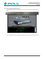
USER GUIDE
C58
HIGH DEFINITION MULTI-PORT IP
STREAMING SYSTEM
Publication: 81-9059-0704-0, Rev. B
www.PESA.com
April 2014
Phone: 256.726.9200
PESA XSTREAM C58 USER GUIDE
Publication 81-9059-0704-0, Rev. B
April 2014
Thank You for Choosing PESA!!
We appreciate your confidence in our products. PESA produces quality, state-of-the-art A/V processing, routing
and distribution equipment designed to deliver our users the highest degree of performance, dependability and
versatility available anywhere. We want you to know that if you ever have a question or concern with a PESA
product, we have a team of engineers, technicians and customer service professionals available 24/7 every day
of the year to help resolve the issue.
Again thank you for choosing PESA, and we look forward to a long-term partnership with you and your facility.
SERVICE AND ORDERING
ASSISTANCE
PESA
103 Quality Circle, Suite 210
Huntsville AL 35806 USA
www.PESA.com
CUSTOMER SERVICE DEPARTMENT
Tel: 256.726.9222 (24/7)
Toll Free: 800.323.7372
Fax: 256.726.9268
Email: [email protected]
MAIN OFFICE
Tel: 256.726.9200
Fax: 256.726.9271
© 2014, 2013, PESA, All Rights Reserved.
No part of this publication (including text, illustrations, tables, and charts) may be reproduced, stored in any retrieval
system, or transmitted in any form or by any means, including but not limited to electronic, mechanical, photocopying,
recording or otherwise, without the prior written permission of PESA.
Microsoft and Windows are either registered trademarks or trademarks of Microsoft Corporation in the United States and/or
other countries.
All information, illustrations, and specifications contained in this publication are based on the latest product information
available at the time of publication approval. The right is reserved to make changes at any time without notice.
Printed in the United States of America.
April 2014 – Rev B
June 2013 – Rev A
I
PESA XSTREAM C58 USER GUIDE
Publication 81-9059-0704-0, Rev. B
April 2014
TABLE OF CONTENTS
CHAPTER 1
ABOUT THIS USER GUIDE....................................................................................... 1-1
1.1
1.2
DOCUMENTATION AND SAFETY OVERVIEW ...................................................................................1-1
CAUTIONS AND NOTES .................................................................................................................1-1
CHAPTER 2
INTRODUCTION ........................................................................................................ 2-1
2.1
2.2
2.3
2.4
2.5
OVERVIEW ...................................................................................................................................2-1
BRIEF FUNCTIONAL DESCRIPTION .................................................................................................2-1
FEATURES ....................................................................................................................................2-3
FRONT AND REAR PANEL LAYOUT ................................................................................................2-4
SPECIFICATIONS ...........................................................................................................................2-5
CHAPTER 3
INSTALLATION.......................................................................................................... 3-1
3.1
3.2
3.3
LOCATION CONSIDERATIONS ........................................................................................................3-1
REAR PANEL LAYOUT ..................................................................................................................3-1
SYSTEM I/O CONNECTIONS ...........................................................................................................3-1
3.3.1
3.3.2
3.3.3
3.3.4
3.3.5
3.3.6
3.3.7
Video Input .................................................................................................................... 3-1
Audio Input.................................................................................................................... 3-2
Gig-E Network............................................................................................................... 3-3
Analog (Line) Audio Output .......................................................................................... 3-3
HDMI Video/Audio ....................................................................................................... 3-3
USB 2.0 Audio Output Stream ....................................................................................... 3-4
USB 2.0 Video/Audio Stream ........................................................................................ 3-4
3.4
3.5
3.6
3.7
INITIAL POWER-UP .......................................................................................................................3-4
NETWORK PARAMETERS AND IP ADDRESS DATA ..........................................................................3-4
RTSP CLIENT CONFIGURATION ....................................................................................................3-4
OPERATING THE PESA XSTREAM IN A WAN ENVIRONMENT OR WITH A CDN................................3-5
CHAPTER 4
OPERATION................................................................................................................ 4-1
4.1
4.2
4.3
4.4
4.5
4.6
4.7
4.8
4.9
4.10
4.11
4.12
4.13
4.14
4.15
THE PESA XSTREAM GUI ............................................................................................................4-1
HOME PAGE .................................................................................................................................4-2
AUDIO CONTROL FUNCTIONS........................................................................................................4-2
INPUT AUDIO MENU FUNCTIONS ...................................................................................................4-3
OUTPUT AUDIO MENU FUNCTIONS................................................................................................4-5
LINE /HEADPHONE AUDIO MENU FUNCTIONS ................................................................................4-6
VIDEO CONTROL FUNCTIONS ........................................................................................................4-7
IP STREAM VIDEO CAPTURE .........................................................................................................4-8
GENERIC RTSP STREAM CAPTURE ................................................................................................4-8
INPUT VIDEO MENU FUNCTIONS ...................................................................................................4-9
OUTPUT VIDEO MENU FUNCTIONS .............................................................................................. 4-11
HDMI OUTPUT MENU FUNCTIONS .............................................................................................. 4-17
SYSTEM MENU FUNCTIONS ......................................................................................................... 4-19
USER ACCOUNT SET-UP PAGE FUNCTIONS (ADMIN LEVEL USERS ONLY) ..................................... 4-21
ABOUT (SYSTEM INFORMATION) PAGE ........................................................................................ 4-22
II
PESA XSTREAM C58 USER GUIDE
Publication 81-9059-0704-0, Rev. B
April 2014
TABLE OF CONTENTS (CONT.)
CHAPTER 5
APPENDICES............................................................................................................... 5-1
5.1
5.2
APPENDIX A - GLOSSARY OF TERMS .............................................................................................5-1
APPENDIX B – LIST OF ACCESSORIES ............................................................................................5-1
LIST OF FIGURES
FIGURE 2-1 PESA XSTREAM C58 – FRONT VIEW ...........................................................................................2-1
FIGURE 2-2 TYPICAL SYSTEM LAYOUT ..........................................................................................................2-2
FIGURE 3-1 REAR PANEL ANALOG AUDIO CONNECTOR .................................................................................3-2
FIGURE 3-2 USING PESA XSTREAM IN A WAN..............................................................................................3-5
FIGURE 4-1 GUI LOG-IN PAGE .......................................................................................................................4-1
FIGURE 4-2 AUDIO SIGNAL FLOW ..................................................................................................................4-3
FIGURE 4-3 VIDEO SIGNAL FLOW...................................................................................................................4-8
LIST OF TABLES
TABLE 3-1 AUDIO INPUT CONNECTOR PIN-OUTS ...........................................................................................3-2
III
PESA XSTREAM C58 USER GUIDE
Publication 81-9059-0704-0, Rev. B
April 2014
Chapter 1 About This User Guide
1.1 DOCUMENTATION AND SAFETY OVERVIEW
This User Guide provides instructions for installation and operation of the PESA XSTREAM High
Definition Multi-Port IP Streaming System designed and produced by PESA.
It is the responsibility of all personnel involved in the installation, operation, and maintenance of the
equipment to know all the applicable safety regulations for the areas in which they will be working.
Under no circumstances should any person perform any procedure or sequence in this manual if the
procedural sequence will directly conflict with local Safety Practices. Local Safety Practices shall
remain as the sole determining factor for performing any procedure or sequence outlined in this
document.
1.2 CAUTIONS AND NOTES
Cautions and Notes are addendum statements used in this guide that supply necessary information
pertaining to the text or topic they address. Caution statements typically notify you of steps or
procedures that could impede installation or operation; and/or cause damage to the equipment. These
additional statements may also provide added information that can simplify and/or enhance the use or
operating characteristics of the equipment (i.e., Notes). Examples of the graphic symbol used to identify
each type of statement and the nature of the statement content are shown below:
Caution statements identify conditions or practices that can result in
personal injury and/or damage to equipment if the instructions contained in
the statement are not complied with.
Notes are for information purposes only. However, they may contain
invaluable information important to the correct installation, operation,
and/or maintenance of the equipment.
1-1
PESA XSTREAM C58 USER GUIDE
Publication 81-9059-0704-0, Rev. B
April 2014
Chapter 2 Introduction
2.1
OVERVIEW
PESA’s XSTREAM is a versatile platform for audio and high definition video processing, and multi-port
IP streaming. It consolidates many A/V signal capture, processing, synchronization, and signal
distribution functions into a single 1 RU package.
An integrated web server supports a browser-based Graphical User Interface (GUI) for passwordprotected access to all operating controls and functions of the PESA XSTREAM (PXS). Since day-to-day
on-site user intervention is not required, PXS may be installed virtually anywhere and controlled from
virtually any computer running a compatible web browser application on the local Ethernet or from
practically anywhere in the world over the internet.
Installation of the PXS is straight forward and GUI operation is very intuitive.
A typical PESA XSTREAM rack unit is shown by Figure 2-1.
Figure 2-1 PESA XSTREAM C58 – Front View
2.2
BRIEF FUNCTIONAL DESCRIPTION
Figure 2-2 illustrates typical system connections to the PXS.
System architecture of the PXS is based on three independent signal processing engines, each of which
supports signal inputs from virtually any of the most widely used source formats. Each processor
provides two output streams of H.264 video, each associated with an AAC audio output stream, for a
total of six A/V IP stream outputs. Plus, the PXS provides HDMI monitor outputs and USB 2.0 outputs
for local recording, editing or archiving.
Each of the three processing engines require a unique network IP address and connect with a remote
client using RTP for transport and the RTSP protocol for connection management. The A/V stream
accessed by a remote client is specified through the IP address of the processor and the channel name.
There are six video processing channels within the PXS circuitry: five select and process video input
signals from external sources, and the sixth produces a quad-view image with the source for each
quadrant chosen from any of the five video input signals.
Each of the five video input channels is associated to one of the rear panel BNC connectors and also has
a decoder to extract streaming video in H.264 format from the network. Through control software, the
active input source for each video channel is selected from either SDI or analog video presented to the
BNC, or a specified streaming video source.
The output signal from each of the six video processing channels is encoded as an H.264 stream for an
RTP/RTSP client; and is also available as an HDMI output with audio for local monitoring and for
computer interface functions through a USB 2.0 connection.
2-1
PESA XSTREAM C58 USER GUIDE
Publication 81-9059-0704-0, Rev. B
April 2014
Each of the eight audio processing channels includes a discrete input connection for analog line level or
microphone level sources; and also provides a decoder function to extract AAC streaming audio
associated with the video when an IP streaming source is specified for any of the video input channels.
Through control software, the active input source for each audio channel is selected from either the rear
panel connector, one of the de-embedded audio signals from an SDI video input, or from a streaming
input signal source. Each channel offers gain and delay adjustments at various points in the signal path.
A software controlled mixing function within each of the audio processing channels allows you to create
a custom audio track containing various levels of any or all of the eight input signals for pairing with
each of the video output signals. Audio and video signals are time-synchronized.
Output signals from six of the processing channels are individually encoded as an AAC stream for
pairing with each of the video output streams for an RTSP client.
Two user-created audio mixer output signals are also available as balanced, line level analog outputs
through rear panel XLR connectors for use as a program or monitor audio source.
Two USB 2.0 ports allow you to interface the outputs of the PXS with external devices:
•
USB port #1, labeled Audio Out, produces a serial output stream containing audio signals present
on all eight processing channels in an uncompressed format.
•
USB port #1, labeled A/V Out, produces a serial output stream containing the signal from all six
video processing channels, plus the audio signal associated with each video channel.
Figure 2-2 Typical System Layout
2-2
PESA XSTREAM C58 USER GUIDE
Publication 81-9059-0704-0, Rev. B
April 2014
Two discrete HDMI outputs allow local monitoring:
2.3
•
The HDMI output labeled A/V Out may be selected through control software to monitor the
signal from any one of the six video processing channels and the audio associated with it.
•
The HDMI Quad View Out port is fixed to monitor the output of the quad-view processing
channel. Audio available at this HDMI output is not associated with any particular video signal
and may be mixed as needed for a unique monitor requirement.
FEATURES
• Captures multiple video and audio signals from a variety of signal formats and sources
• Five internal video processing channels, eight internal audio processing channels and an internal
quad-view multiviewer as a sixth video processing channel
• Mixing functions to create custom audio track for each video signal
• Six simultaneous and individually addressable IP output streams
• Single Unicast, Multiple Unicast or Multicast streaming mode may be selected individually for
each of the six output streams
• Time synchronized audio to video for “lip-sync” error correction
• HDMI output for quad-view display*
• HDMI output for full screen view of single selected video output*
• USB 2.0 output containing data stream with video output signal from all processing channels, plus
audio signal associated with each video channel
• USB 2.0 output containing data stream of all 8 audio pre-mix channels in an uncompressed format
• Two line level XLR audio output connections
• Front mounted, standard ¼” stereo headphone jack for audio monitoring
• Dual ports RJ-45 for Gig-E network connections
• Support RTP, RTCP and RTSP protocols**
* HDMI output can be converted to BNC connectivity using the optional PESA HDMI2BNC Converter
** RTSP output can be converted to RTMP format using a third party transcoder
2-3
PESA XSTREAM C58 USER GUIDE
Publication 81-9059-0704-0, Rev. B
April 2014
2.4
FRONT AND REAR PANEL LAYOUT
2
1
3
4
5
1. Power ON Indicator LED
2. Ethernet active link and network activity indicators for Gig-E ports 1 and 2
3. Active link indicators for USB 2.0 ports
4. Video input status indicators
5. 1/4” stereo headphone jack for monitoring analog audio output mixes
6
7
8
9
10
11
12
13 514
6. 25 pin “D” connector for connection of balanced or unbalanced analog audio sources 1 - 8
7. XLR output ports for analog Line Out audio mixes 1 and 2
8. Audio Out USB 2.0 port providing serial digital output of all eight audio processing channels
9. HDMI output ports:
Quad View Out – dedicated monitor output of the sixth (quad-view) video processing channel
AV Out – User selectable monitor output of any desired video processing channel 1 thru 6
10. A/V Out USB 2.0 port providing serial digital output of all video processing channels (five video
input channels plus the quad-view channel)
11. Gig-E Ethernet ports:
PESA XStream has a 2 port Ethernet switch built-in, you may use either port for connection to the
Ethernet
12. BNC connectors for input of analog or SDI video sources
13. IEC 320C14 power input connector (100 – 240 VAC, 50/60 Hz)
14. Main power switch with lighted “ON” indicator
2-4
PESA XSTREAM C58 USER GUIDE
Publication 81-9059-0704-0, Rev. B
April 2014
2.5
SPECIFICATIONS
VIDEO INPUTS
Number
Source
BNC
Number
Type
Formats
Return Loss
Equalization
IP Video
Connection
Format
Connector
Supported IP
Cameras:
5 Video processing channels
BNC input or decoded from IP stream
5 BNC connectors
Standard 75 Ohm, self-terminating
Analog: NTSC/PAL
Digital: SMPTE ST-292 (720p, 1080i), ST-424 (1080p)
≥15dB 1MHz to 1.5GHz; ≥10dB, 1.5GHz to 3GHz.
200m auto-equalization Belden 1694A or equivalent at 1.5Gbps;
140m auto-equalization Belden 1694A or equivalent at 3.0Gbps
RTP/RTSP
H.264 (MPEG 4/Part 10)
2 RJ-45 for 100/1000 Gig-E port
Cisco 4500
Axis M1054
Axis M1114
Support for additional IP cameras is being added on a regular
basis. Contact PESA if the specific camera you are using is not
listed, or attempt data capture using the Generic RTSP Capture
capability of the PXS. Refer to Paragraph 4.9.
AUDIO INPUTS
Source
Number
- Analog audio, Line/mic level, 8 channels
- De-embedded from SDI video input, up to 10 available sources
- AAC audio decoded from IP stream associated with IP video input signal, up
to 5 available sources
- Test tone, internally generated
8 Audio processing channels, selected from any of the above sources
Analog Audio
Type
25 Pin D connector
Optional XLR breakout cable for 8 connections available
Format
Balanced
Audio Level
Mic level with user selectable “phantom power” or
line level inputs
Gain Adjustment +12dB to -40dB line level/+59dB to 0 dB mic level
2-5
PESA XSTREAM C58 USER GUIDE
Publication 81-9059-0704-0, Rev. B
April 2014
IP STREAMING
Number
6 Individually addressable IP streams: five streams each containing video from one
of the five input processing channels plus the audio signal associated with each
video channel; the sixth stream containing signal from the quad-view processor plus
audio signal associated to the quad-view channel
Streaming Mode Single unicast, multiple unicast or multicast – independently selectable for each
stream
Connection
RTP/RTSP
Format
Video: H.264 (MPEG 4/Part 10),
Audio: AAC
Video Resolution 720p, 30fps; 720p, 60fps; 1080p, 30fps; 1080p, 60fps
Streaming Rates (selectable) 0.5Mb, 0.75Mb, 1Mb, 2Mb, 4Mb
Connector
2 RJ-45 for 100/1000 Gig-E Ethernet port
AUDIO/VIDEO OUTPUTS
HDMI
Number
1 Full screen (selected from any video processing channel, plus audio
signal associated with channel for streaming output)
1 Quad-view (dedicated to quad-view video processing channel, plus
audio signal associated with quad-view channel for streaming output)
Resolution
720p, 60fps
USB
Type
1 USB 2.0 containing data stream with video output signal from all processing
channels, plus audio signal associated with each video channel
SDI (with external HDMI to HD-SDI converter kit)
Number
Up to 2, using available accessories
AUDIO OUTPUTS
Analog
Number
2 (XLR line level – balanced), 1 Headphone
Headphone
¼” Stereo jack – front panel mounted
Audio Out 1 on left channel output and Audio Out 2 on right channel
output
USB
Type
1 USB 2.0 containing data stream of all 8 audio pre-mix channels in an
uncompressed format
NETWORK CONNECTIONS
Number
2 RJ-45
Type
Gig-E (100/1000) Ethernet
2-6
PESA XSTREAM C58 USER GUIDE
Publication 81-9059-0704-0, Rev. B
April 2014
MECHANICAL
Form Factor
Mechanical
Weight
1RU
19.00W X 1.75H X 10.50 D
482.6 mm X 44.45 mm X 266.7 mm
4lbs
ENVIRONMENTAL and MISCELLANEOUS
Control
Ethernet
Control Connection
RJ-45
AC Input Connections IEC 320C14 socket (accepts IEC 320 C13 line cord)
Network Control
Supports PESA web-based control or by SDK kit
Input Voltage
100-240 VAC, 50-60Hz
Operational Temp
0-40 degrees C
Operational Humidity 90% Non-condensing
2-7
PESA XSTREAM C58 USER GUIDE
Publication 81-9059-0704-0, Rev. B
April 2014
Chapter 3 Installation
3.1
LOCATION CONSIDERATIONS
Your PXS may be mounted in a standard 19 inch equipment rack using the attached rack mount
brackets. When the chassis is rack mounted, always ensure there is adequate clearance for air circulation
around all sides. If your installation does not incorporate an equipment rack, you may remove the rack
brackets and place the chassis on a desktop or other convenient location.
Regardless of installation location, ensure that adequate space is allowed for ventilation. The PXS uses
forced air fan cooling and must be located such that there is no obstruction blocking any of the fans.
Also consider access to video and audio cabling and a convenient Ethernet network drop.
3.2
REAR PANEL LAYOUT
With the exception of the headphone audio monitoring jack, all video, audio and network connections to
the PXS are made through connectors located on the rear panel, as shown in Paragraph 2.4. Use this
figure as a reference when completing connections to the chassis.
To ensure compatibility with virtually any A/V system installation or application, PESA XSTREAM
provides audio and video interface through many of the most common industry-standard formats and
connectors.
3.3
SYSTEM I/O CONNECTIONS
3.3.1 VIDEO INPUT
The PESA XSTREAM provides a total of five video processing channels with the signal input for each
available from either a discrete video input source attached directly to a rear panel connector; or, in
many applications, from video decoded from an H.264 stream. When streaming video is selected as a
signal source, the PXS functions as an RTSP client to connect with the server streaming the desired
video source. Typically the streaming signal is video from an IP camera.
Discrete Video Input Signals: Five rear panel mounted BNC connectors allow input of discrete SDI
video signals up to 1080p/60 resolution. Connect the video source directly to the rear panel BNC
connector.
H.264 Streaming Inputs: There is no channel specific hook-up required for a streaming video source.
Through control software you may configure up to five streaming sources by RTSP connection and
select a decoded video signal for any of the five video processing channels.
IP cameras must be on a LAN connected to the PXS. The PXS
does not connect to cameras via a WAN.
3-1
PESA XSTREAM C58 USER GUIDE
Publication 81-9059-0704-0, Rev. B
April 2014
3.3.2 AUDIO INPUT
The PESA XSTREAM provides a total of eight audio input channels with the signal input for each
available from either a discrete input directly to the device, such as a microphone, an audio signal deembedded from an SDI video input signal, or, in many applications, from audio decoded from an AAC
stream.
Discrete Audio Input Signals: Discrete analog audio connections are made through the 25-pin “D”
connector on the chassis rear panel, as shown by Figure 3-1. This connector provides input capability
for up to 8 microphone or line level, balanced or unbalanced, analog audio input signals. A switchable
source of phantom power for condenser microphones is available for each audio input source. Phantom
power may be turned on or off through the PXS control GUI. You may connect audio sources through a
mating “D” connector using the pin-outs as identified in Table 3-1. PESA also has an optional adapter
cable available that mates directly to the rear panel input connector and provides a fan-out to 8 XLR
connectors, one for each analog input source.
Figure 3-1 Rear Panel Analog Audio Connector
Audio In
Pin #
Audio In
Pin #
Channel 1 +
Channel 1 GND
24
12
25
Channel 5 +
Channel 5 GND
18
6
19
Channel 2 +
Channel 2 GND
10
23
11
Channel 6 +
Channel 6 GND
4
17
5
Channel 3 +
Channel 3 GND
21
9
22
Channel 7 +
Channel 7 GND
15
3
16
Channel 4 +
Channel 4 GND
7
20
8
Channel 8 +
Channel 8 GND
1
14
2
Table 3-1 Audio Input Connector Pin-Outs
3-2
PESA XSTREAM C58 USER GUIDE
Publication 81-9059-0704-0, Rev. B
April 2014
Be sure that phantom power is off unless a microphone that
requires it is attached to the analog input connector.
De-embedded SDI Audio: When an SDI video signal is used as the input source for any of the video
processing channels, the first two embedded audio signals within the first audio group are automatically
de-embedded and available as audio source signals. Through control software you can select any one of
up to ten possible de-embedded audio signals as an audio source signal for each of the eight audio
processing channels.
Streaming Audio Inputs: Streaming audio signals for use as a channel source are always associated to
one of the streaming video signals. Through control software you select one of the five available
streaming video signals for the audio channel input, and the AAC audio stream associated to that video
becomes the audio signal source for the channel.
The actual audio source is selected through control software. It is not necessary to physically disconnect
a discrete audio signal source from the XLR connector for an input channel if you wish to modify a
configuration and select a de-embedded signal or a streaming source for that channel.
3.3.3 GIG-E NETWORK
PESA XStream has a 2 port Ethernet switch built-in. You may use either RJ-45 port to connect the PXS
to the Ethernet. Refer to Paragraph 3.5 for IP addressing and network connection information.
3.3.4 ANALOG (LINE) AUDIO OUTPUT
Each XLR connector provides a line-level, balanced, monaural output audio signal that may be used as
program audio output, or used for monitoring/recording purposes. Through control software, you may
create a custom audio signal mix for each output from any or all of the eight pre-mix or seven post-mix
audio channels.
You may monitor the audio outputs using stereo headphones attached to the front-panel Headphone
jack. Line Out 1 audio is heard in the left headset channel, and Line Out 2 in the right channel. Through
control software, the level of each monitor channel may be adjusted.
3.3.5 HDMI VIDEO/AUDIO
PESA’S XSTREAM provides two HDMI* output connections that may be used for local monitoring.
The connector labeled Quad View Out, always displays the output of the quad-view video processing
channel and may not be changed. Audio for this output is a dedicated signal that may be mixed from any
or all of the post-mix audio output channels.
The connector labeled A/V Out, can display the output of any one of the six video processing channels
as selected through control software. Audio for this output is the same signal mix associated with the
selected video channel.
Connect a compatible monitor or other HDMI device to each output as desired.
*HDMI outputs can be converted to BNC outputs using the
optional PESA HDMI2BNC Converter Module.
3-3
PESA XSTREAM C58 USER GUIDE
Publication 81-9059-0704-0, Rev. B
April 2014
3.3.6 USB 2.0 AUDIO OUTPUT STREAM
The USB 2.0 port labeled Audio Out provides a serial output stream containing the pre-mix audio source
signal from all eight audio processing channels in an uncompressed format.
3.3.7 USB 2.0 VIDEO/AUDIO STREAM
The USB 2.0 port labeled A/V Out provides a serial data stream containing the output from all six video
processing channels, plus the audio signal associated with each video channel.
3.4
INITIAL POWER-UP
Provide a source of power to the PXS. Verify your connections before you apply power for the first
time.
Also verify that the default IP addresses used by the PXS for network connection are compatible with
your facility LAN, you may need to consult your IT administrator for this. If any of the IP addresses of
the PXS need to be changed to accommodate your network, refer to Paragraph 3.5.
Apply power to the PXS with the rear panel switch and verify the power indicator lamp is lit. You
should begin to see front panel LED indication of activity on the Ethernet connection(s).
Configure your RTSP client device per Paragraph 3.6 to connect with the PXS server. Video and audio
selections and all configuration operations are made through the control GUI, refer to Chapter 4.
3.5
NETWORK PARAMETERS AND IP ADDRESS DATA
Factory default IP address for the PESA XSTREAM processors are:
Processor 1 – 192.168.1.100
Processor 2 – 192.168.1.101
Processor 3 – 192.168.1.102
Changes to the IP address parameters are made through the software control GUI (Paragraph 4.13) that
you access through a common web browser running on a PC. To access the GUI enter the IP address of
Processor 1 into the address bar of the browser. Refer to Paragraph 4.1 for the GUI access procedure.
If the factory default addresses are not compatible with your LAN, and you can not access the GUI over
the facility network, it will be necessary to modify the address with the PXS and a PC in a direct
Ethernet connection while not connected to the LAN. Configure the PC to communicate with the PXS
using the default settings shown above, and access the control GUI per Paragraph 4.1. Change the IP
addresses of the processors as needed for network compatibility.
It is not necessary that the three processor IP addresses be sequential.
3.6
RTSP CLIENT CONFIGURATION
The PESA XSTREAM uses the RTSP protocol and RTP transport for connecting and streaming to a
remote client within the LAN. In order to complete a connection, the client must send the proper
connection request message in the correct syntax. Each of the three video processing engines is assigned
a unique IP address. You must know the address of the processor sending the stream you wish to
capture to complete a connection using the following guide:
Output Stream 1 or 2 – IP address of processor 1
Output Stream 3 or 4 – IP address of processor 2
Output Stream 5 or 6 – IP address of processor 3
3-4
PESA XSTREAM C58 USER GUIDE
Publication 81-9059-0704-0, Rev. B
April 2014
The RTSP client device or application must initiate connection with the PXS server by sending a
character string containing the following parameter data in the following syntax:
rtsp:// <IP Address> : <Access Port> / <Channel Name>
where:
• IP address is the address of the PXS processor sending the stream you wish to capture.
• Access Port identifies the port number.
• Channel Name identifies the stream from the processing engine you wish to capture. For PXS, the
channel name is OCH.1 or OCH.2, where the numeral identifies stream 1 or stream 2 from the
processor.
To connect with PESA XSTREAM, a connection request message should follow the syntax of the
example shown below. The IP address and port number shown here are for example only and not
necessarily meant to be an actual working parameter.
rtsp://192.168.1.58:544/OCH.1
3.7
OPERATING THE PESA XSTREAM IN A WAN ENVIRONMENT OR WITH A CDN
When operating or installing the PXS in a wide area network (WAN) environment, it may be necessary
to utilize a third party transcoder to convert the PXS RTSP output into an RTMP format for delivery
over a WAN to third party content distribution networks (CDN)s. This configuration is shown in Figure
3-1.
Figure 3-2 Using PESA XSTREAM in a WAN
3-5
PESA XSTREAM C58 USER GUIDE
Publication 81-9059-0704-0, Rev. B
April 2014
Chapter 4 Operation
4.1
THE PESA XSTREAM GUI
All set-up and control functions of the PESA XSTREAM are performed through GUI commands. You
may access the GUI through a web browser running on a PC with Ethernet connection to the PXS
device. With your PXS installed on the LAN and powered-up, point your web browser application to the
IP address of the PXS web server to access the GUI.
The IP Address for the PXS Web Server is always the same address as
Processor 1. Factory default IP address is 192.168.1.100.
An example of the GUI login display is shown by Figure 4-1.
Figure 4-1 GUI Log-In Page
From the login page you may access the control GUI for the first time by entering the default credentials
shown below, followed by clicking the Submit button:
User ID: admin
Password: a
4-1
PESA XSTREAM C58 USER GUIDE
Publication 81-9059-0704-0, Rev. B
April 2014
Using the default credentials, you will be logged in to the permanent administrator account. This
account can never be deleted; however, you may change the password at any time. Through this
account, additional users may be added and assigned administrator or staff access privileges.
Staff access users have full access to system configuration menus and pages, with the exception of the
Users page. Only an administrator can add or delete users, or change user passwords.
4.2
HOME PAGE
The GUI initially opens to the Audio Input page, which is also the home page, as shown below.
4.3
AUDIO CONTROL FUNCTIONS
Audio processing functions of the PESA XSTREAM allow you to select the input signal for each of up to
eight audio processing channels from a variety of signal sources and internally mix signals from any or
all of the processing channels for embedding into the streaming and HDMI video output channels.
PESA XSTREAM also allows you to select the source for up to two analog audio outputs that may be
used for program audio, recording or monitoring applications.
A simplified signal flow diagram of a single audio processing channel is shown by Figure 4-2. Operator
controls and set-up functions available through GUI screens are indicated by functional blocks of the
diagram.
4-2
PESA XSTREAM C58 USER GUIDE
Publication 81-9059-0704-0, Rev. B
April 2014
Figure 4-2 Audio Signal Flow
4.4
INPUT AUDIO MENU FUNCTIONS
Click the Input Audio tab at the top of display to access the input audio control grid. This page is also
the Home page for the PXS control GUI.
Using controls on the Input Audio page, you can select the source and enter set-up parameters of the
input signal for all eight audio processing channels, Audio 1 thru Audio 8, and enter a descriptive label
for each channel. At this point in the processing chain, each signal is at the pre-mix stage.
4-3
PESA XSTREAM C58 USER GUIDE
Publication 81-9059-0704-0, Rev. B
April 2014
The input audio control grid contains eight rows – one for each of the audio processing channels as
identified in the Label column. By factory default the processing channels are labeled as Audio 1 –
Audio 8. You may, however, enter a descriptive name for each channel by editing the text in the Label
cell for the channel, as shown in the example above. Press Enter on the keyboard to accept the text
changes and immediately write the new channel label to system memory.
Audio Input – Each field in the column contains a pull-down menu where you select the desired audio
source for the processing channel from the following options:
Line Mic 1 – 8
Select the microphone or line level audio source 1 thru 8 present at the
analog input “D” connector pins ( XLR connector when the optional
breakout cable is used).
IP 1 – 5
Select the decoded AAC audio associated with the video input for any
of the five processing channels when a streaming input source is
selected for a video processing channel.
SDI 1A – 5B
Select one of the two audio signals de-embedded from channel group
one of the video input on any of the five processing channels when an
SDI input source is selected for the video processing channel.
Test Tone
Select an internally generated test tone as input for the audio
processing channel.
Phantom Power – Clicking in this box on any row applies a source of +48 VDC phantom power to the
microphone present at the XLR input connector for the indicated analog input. A check in the box
indicates the power source is active. Toggle the phantom source off by clicking again in the box.
The phantom power selection is only available when the audio
input is selected as an analog source, and should only be activated
when a condenser type microphone, or other device, that requires
such a power source is connected to the input.
Analog Gain – Use the up and down arrows to set the desired amount of pre-amp gain applied to the
incoming analog signal. This selection is only available when an analog source is selected as the audio
input for the channel.
Digital Gain – Regardless of the source of the audio input signal (analog, IP, or de-embedded from SDI
video), every audio processing channel converts its input to a digital format signal for use by the
processing circuitry. The Digital Gain function is downstream of the Audio Input selector and digital
conversion process, and determines the master level of the audio source. Use the up and down arrows to
set the gain to the desired signal level.
Delay – Allows you to add a delay to the audio source prior to the mixing function. Use the up and
down arrows to set a delay value between 0 and 2.7 seconds.
Label – Allows you to enter a descriptive name for each of the audio processing channels. This label is
used to more easily identify a processing channel in downstream control grids.
4-4
PESA XSTREAM C58 USER GUIDE
Publication 81-9059-0704-0, Rev. B
April 2014
4.5
OUTPUT AUDIO MENU FUNCTIONS
Click the Output Audio tab at the top of the display to access the control page, as shown below.
One of the unique features of PESA XSTREAM is the ability to create a custom audio mix that is
associated with each of the video output channels. You may blend audio from any or all of the eight premix signals into the output signal for each audio processing channel. All mixing and output control
functions are done through the Output Audio page.
Audio Mixing Matrix – An audio mixer is a matrix of input channels and at least one output bus, or
channel. A fader device for each input channel determines the level (volume) of each input signal, if any
at all, present in the signal of each mixer output channel. The PXS mixing grid is a software
implementation of an 8 input by 7 output audio mixer.
Each of the first eight columns in the grid is an input channel for one of the pre-mix audio signals we
set-up through the Input Audio menu, see Paragraph 4.4. Columns are identified by the channel label
assigned to the processing channel. Each column contains seven rows that define the output channels of
the mixer. Following the mixing function in the processing chain, each signal is at the post-mix stage.
At the intersection of each output channel row and pre-mix input column is a field with up and down
arrows that effectively become the “fader” for the input signal. Volume level for each input source is
adjusted in terms of what percentage of the input signal level is added to the output channel bus.
For example, if you wanted to encode the audio input on the pre-mix channel labeled Camera 1 as the
AAC output stream associated with video streaming channel 1, you would click the up arrow in the
adjustment field to 100, as shown below.
4-5
PESA XSTREAM C58 USER GUIDE
Publication 81-9059-0704-0, Rev. B
April 2014
Now, suppose there is a source of music on the pre-mix channel labeled Music Server that you would
like to add softly in the background. You would use the adjustment arrow to set the percentage of the
signal you want to add to the mix, as shown below. In this illustration, we have added the background
source at 10% of its full level.
Gain –The Gain adjustment for each post-mix output channel is downstream of the mixing matrix, and
determines the master output level of the audio signal to the audio encoder. Use the up and down arrows
to set the gain to the desired signal level.
Delay – Allows you to add a delay to the audio signal prior to the encoding function. Use the up and
down arrows to set a delay value between 0 and 2.7 seconds.
Mute – Clicking in this box on any row mutes the signal to the audio encoder. A check in the box
indicates the signal is muted. Toggle the mute function by clicking again in the box.
Using controls on the Output Audio page, you can blend a custom audio mix for each of the seven postmix audio channels, and set operational parameters for each. Audio output processing channels are
labeled IP Stream 1 thru IP Stream 6 and HDMI Out Quad View. IP streaming output channels 1 thru 6
are encoded as AAC serial data streams and are the audio signals associated with H.264 streaming video
output channels 1 thru 5 (IP Stream 1 thru IP Stream 5) and the quad-view streaming video output
channel (IP Stream 6). The seventh post-mix audio channel is associated with the quad-view HDMI
output port (HDMI Quad View Out).
4.6
LINE /HEADPHONE AUDIO MENU FUNCTIONS
Click the Line/Headphone Audio tab at the top of the display to access the control page, as shown
below.
The PXS provides two analog audio output signal paths, labeled Line 1 and Line 2, which may be used
for monitoring or as audio-only program outputs. Each output signal is available through a rear panel
XLR connector. In addition to the XLR output, each analog signal also drives one channel of a frontpanel mounted stereo headphone jack. By this arrangement, you can simultaneously monitor both
analog outputs through a pair of stereo headphones with one of the outputs in each stereo channel.
4-6
PESA XSTREAM C58 USER GUIDE
Publication 81-9059-0704-0, Rev. B
April 2014
You may choose any one of the eight pre-mix audio signals or any one of the seven post-mix signals as
the source for each analog audio output; optionally apply a delay to the signal, if desired; and
independently set the desired output level for both the line output and the headphone monitor.
All control functions are done through the Line/Headphone Audio page.
Input Select – the fields in this column contain a pull-down menu where you select the desired audio
source for each line out / headphone monitor pair from the following options:
Main Audio 1 – 8
Select the audio signal from one of the eight pre-mix processing
channels. Processing channels are identified in the pull-down list by
the label designated for the channel, or by the default labels of Audio
1 thru Audio 8.
IP Audio 1 – 6
Select one of the six post-mix signals associated with streaming video
output channels 1 thru 5 (IP Audio 1 thru IP Audio 5) or the quadview streaming video output channel (IP Audio 6).
HDMI Audio 1
Selects the post-mix signal embedded into the HDMI quad-view video
output channel (HDMI Audio 1).
Delay – Allows you to add a delay to both the line output and headphone monitor audio signal. Use the
up and down arrows to set a delay value between 0 and 2.7 seconds.
Gain – A pair of independent Gain adjustments for the line output level and the headphone level are
provided downstream of the delay function. Use the up and down arrows to set the desired gain for each
output.
Mute – Clicking in this box on any row mutes the audio output signal. A check in the box indicates the
signal is muted. Toggle the mute function by clicking again in the box.
As indicated by the layout of the GUI page, Line Out 1 is audible in the left channel of the stereo
headphones for monitoring, and Line Out 2 is audible in the right headset channel.
4.7
VIDEO CONTROL FUNCTIONS
Video control functions of the PXS are selected from the tabs at the top of the GUI display area, and
allow you to select a signal source for each of the five video processing channels from an analog or
digital video device or IP stream source, and set the IP network communication and access parameters
for each signal path. Other functions allow you to set the operating and access parameters for PESA
XSTREAM’s output streams, and select the video sources for the HDMI monitor outputs.
A simplified signal flow diagram of a typical video processing channel is shown by Figure 4-3.
4-7
PESA XSTREAM C58 USER GUIDE
Publication 81-9059-0704-0, Rev. B
April 2014
Figure 4-3 Video Signal Flow
4.8
IP STREAM VIDEO CAPTURE
In order to capture a video source from a network stream the PXS functions as an RTSP client and must
initiate a connection with the server streaming the desired signal. Specifics of the connection including
the channel identifier or filename, password protection, etc. vary by streaming source.
Operating firmware of the PXS includes access capability for network cameras commonly found in
installations using the PXS device.
If the device or source you wish to capture is not currently in the PESA XSTREAM device library, the
Generic RTSP capture mode may be able to help, refer to Paragraph 4.9.
4.9
GENERIC RTSP STREAM CAPTURE
If you wish to capture a streaming source from an RTSP server that is not currently contained in PESA
XSTREAM’s library of devices, you may be able to configure the Generic RTSP function to capture the
stream. Generic RTSP mode is selected from the Input Video menu, IAW Paragraph 4.10.
In order to communicate with a server using Generic RTSP, the server must be sending the stream using
the RTSP communication protocol over an RTP transport stream. To initiate the client/server
handshake, you must have the following information:
• IP address and access port number of the RTSP server
• Filename, other identifying name or character string to identify the stream you wish to capture
Generic RTSP capture communicates only with open access servers (no password or other security
measure required).
When you select Generic RTSP mode from the Input Video menu, PXS builds a character string using
parameter data you enter in the fields of the input source row, in the following syntax. Text shown in
brackets < > identifies the field by column name where data for the string is entered:
rtsp:// <RTSP IP Address> : <RTSP Port> / <Username>
where:
• Parameter data you enter in the RTSP IP Address field is the IP address PXS uses to attempt
communication with the RTSP server
• Parameter data you enter in the RTSP Port field is the access port PXS uses to communicate with
the server application.
4-8
PESA XSTREAM C58 USER GUIDE
Publication 81-9059-0704-0, Rev. B
April 2014
• Parameter data you enter in the Username field is the character string of the filename, channel
name, or other identifying name or character string that identifies the stream you wish to capture
When you save the data entries on the GUI menu, PXS immediately attempts to initiate communication
with the specified RTSP server. If the connection is accepted, decoded video appears as the input source
for the indicated processing channel.
4.10 INPUT VIDEO MENU FUNCTIONS
Click the Input Video tab at the top of the display to access the control screen, as shown in the example
illustration below. The screen is in the form of a spreadsheet grid with individual cells for each data
entry.
Using controls on the Input Video page, you select the source and enter set-up parameters of the input
signal for the five video processing channels, Video 1 thru Video 5, and enter a descriptive label for
each channel.
Anytime a new entry or change to an existing entry is made to any cell in the grid, the cell is highlighted
in yellow and the message Unsaved Changes is displayed at the top of the grid, as shown in the
following illustration. Once you have made all required entries or edits to the grid, click the Save button
to apply the changes and remove the message prompt. Click Cancel to clear changes you have entered
without saving or applying the changes.
The input video control grid contains five rows – one for each of the video processing channels
identified in the Label column. By factory default the processing channels are labeled as Video 1 –
Video 5. You may, however, enter a descriptive name for each channel by editing the text in the Label
cell for the channel, as shown in the example above. Press Enter on the keyboard to accept the text
changes and immediately write the new channel label to system memory.
4-9
PESA XSTREAM C58 USER GUIDE
Publication 81-9059-0704-0, Rev. B
April 2014
The purpose of each cell is introduced below:
Source – Each field in the column contains a pull-down menu where you select the desired video signal
source for the processing channel from the following options:
Analog In (NTSC/PAL)
Selects the video signal connected to rear panel Video Input BNC for
the processing channel (Video 1 derives its signal from BNC 1, etc.)
as the source for the processing channel, and specifies that the input
signal is from an analog NTSC or PAL video source.
Digital In (SDI)
Selects the video signal connected to rear panel Video Input BNC for
the processing channel (Video 1 derives its signal from BNC 1, etc.)
as the source for the processing channel, and specifies that the input
signal is from an SDI digital video source.
IP Stream
In this mode, the XStream emulates an RTSP client with the captured
video and audio signals available as input sources. Network address,
device address and other parameters required to capture the video
stream are entered in the remaining fields of the row.
Unused (color fill)
Indicates there is no video input signal for the video processing
channel. An internally generated solid color fill screen signal is
present on the processing channel.
Device Type – When IP Stream is selected as the input signal source for a video processing channel, a
pull-down menu in the Device Type column may be opened to a listing of IP cameras currently
supported by the PXS RSTP client function. Fields in this column are only active when IP Stream is
selected in the Source column for the processing channel. Each Device Type pull-down menu currently
contains the following options:
Generic RTSP
Selecting the Generic RTSP function allows the RTSP client to
capture video from certain compatible IP streams from network
sources when all of the required connection parameters are known for
the RTSP server and entered in the fields on this page for the video
processing channel. Refer to paragraph 4.9.
Cisco 4500, Axis M1054, Axis M1114
The remaining items in the current listing identify by brand and model
number the IP cameras currently supported by the PESA XStream.
Selecting any of these choices automatically configures the XStream
RTSP client to receive streaming video from the selected device.
Supported IP streaming devices are added as required; therefore,
the pull-down menu in your GUI revision may not exactly match
the example list shown here. However, the functions are the same
regardless of the actual content of the list.
4-10
PESA XSTREAM C58 USER GUIDE
Publication 81-9059-0704-0, Rev. B
April 2014
Network Parameter Fields – The remaining columns in each row of the menu grid allow you to enter
specific parameters for the IP video device or stream when IP Stream is selected as the input signal
source for a video processing channel. HTTP and RTSP IP address and access port parameter data
should be supplied to you by a network administrator or other source. Username and Password fields
allow you to enter the secure access information for the indicated IP device. If Generic RTSP mode is
selected, the Username field is where you enter the filename or channel name of the desired video
stream from the RTSP server, and the Password field is not used.
Label – Allows you to enter a descriptive name for each video processing channel. This label is used to
more easily identify a processing channel in downstream control grids.
4.11 OUTPUT VIDEO MENU FUNCTIONS
Click the Output Video tab at the top of the display to access the control screen, as shown in the
example illustration below. The screen is in the form of a spreadsheet grid with individual cells for each
data entry.
The PESA XSTREAM provides six IP output streams; each containing an H.264 encoded video signal
and the AAC encoded audio signal associated with the video. Each stream connects with a client device
over an RTP transport using the RTSP communication protocol. Parameters and options entered through
the Output Video menu page allow you to configure PESA XSTREAM’s IP output streams.
The video source signal for each of the IP stream outputs is derived from the output of one of the five
video processing channels or the quad-view processing channel output. The video output control menu
contains six rows, one for each of the output IP streams. The left-most column identifies the video
processing channel, by label, from which the signal source for the IP stream is derived. The video
processing channel to IP stream association is fixed and can not be modified.
4-11
PESA XSTREAM C58 USER GUIDE
Publication 81-9059-0704-0, Rev. B
April 2014
When a new entry or change to an existing entry is made to any cell in the grid, the cell is
highlighted in yellow and the message Unsaved Changes is displayed at the top of the grid,
as shown in the following example. Once you have made all required entries or edits to the
grid, click the Save button to apply the changes and remove the message prompt. Click
Cancel to clear changes you have entered without saving or applying the changes.
Any four of the five video processing channel signals may be inserted in the quadrants of the quad-view
signal channel. You select the desired video signal for each quadrant through a pull-down menu on the
HDMI Output tab. Refer to Paragraph 4-12.
Each of the IP streams may be password protected such that any RTSP client attempting to establish a
connection with the PXS server channel must have the correct username and password in order for the
connection to be completed.
Enable Password – Clicking in this box on any row enables password protection for the RTSP channel.
A check in the box indicates password protection is active. Toggle the password function by clicking
again in the box.
Username and Password – When you have enabled password protection for the RTSP channel, enter,
in their respective columns, the desired Username and Password you will require a client device to send
in order to connect with the PXS output stream. If you enable password protection, you must enter both
a username and password in the fields.
Output Resolution – Each row in this column contains a pull-down menu where you select the desired
output resolution and frame rate for the streaming output from the available options shown here:
Encoder Settings – Clicking any of the three “Change” buttons in this column opens a dialog box that
allows you to select the desired settings for the H.264 encoder for each output channel of the indicated
pair. An example dialog box showing the settings for output channels 1 and 2 is shown below:
4-12
PESA XSTREAM C58 USER GUIDE
Publication 81-9059-0704-0, Rev. B
April 2014
• I-Frame Interval - Intra coded frame also
known as Key frames. I-frames are coded
without reference to any frame except
themselves and can be used to create random
access points in the video. This will allow the
decoder to start decoding properly at that picture
location. Select the I-frame interval from the
pull-down menu options.
• IDR Frames - An encoder sends an IDR
(Instantaneous Decoder Refresh) coded picture to
clear the contents of the reference picture buffer.
On receiving an IDR coded picture, the decoder
marks all pictures in the reference buffer as
unused for reference. An IDR frame specifies
that no frame after the IDR frame can reference
any frame before it. This makes seeking the
H.264 file easier and more responsive in a player.
Select the IDR frame value from the pull-down
menu options shown here.
• Target Bit Rate - The setting chosen from the Target
Bit Rate pull-down menu, in conjunction with Rate
Control defines the output streaming rate for the
encoder.
4-13
PESA XSTREAM C58 USER GUIDE
Publication 81-9059-0704-0, Rev. B
April 2014
• Rate Control - Constant Bit Rate (CBR) encoding
and Variable Bit Rate (VBR) encoding are two
techniques for controlling the bit rate of the
compressed video stream.
If you are not sure of the bitrate to use for your specific
application or for a particular installation, PESA recommends
that you start streaming at a low bitrate then increase the setting
as you verify compatibility with your local area network and with
external equipment.
• Profile - The H.264 standard has many sets of
capabilities which are referred to as profiles. A
profile defines specific encoding techniques that can
be used by decoders to decode the video. Choose the
desired output stream profile from the pull-down
menu options.
• Level - A Level is a specified set of constraints that
indicate a degree of required decoder performance for
a profile. The level of support within a profile specifies
the maximum picture resolution, frame rate, and bit
rate that a decoder may use.
• Entropy - CABAC (Context-adaptive binary
arithmetic coding) More efficient (e.g. better
quality), but harder to decode for use in
Main/High profile only. CAVLC (Contextadaptive variable-length coding) is less
efficient but easier to decode. It is best to use
CABAC when encoding with Main/High
4-14
PESA XSTREAM C58 USER GUIDE
Publication 81-9059-0704-0, Rev. B
April 2014
Advanced Settings – Clicking any of the “Change” buttons in this column opens a dialog box that
allows you to select operating parameters for the indicated output channel from the options shown
below:
• Channel Name – You may enter a name for the output stream that is used within the RTSP
connection request message from a remote client. Channel names may use any of the following
valid characters:
- Alpha characters A-Z or a-z
- Numerals 0 – 9
- Period ( . ), Underscore ( _ ) or Dash ( - )
- Spaces are not allowed
You may assign the stream a name that, for example, identifies the stream or describes its contents.
In order to receive the output stream from the PXS, the RTSP client device or application must
initiate connection with the PXS server by sending a character string containing the following
parameter data in the following syntax:
rtsp:// <IP Address> : <Access Port> / <Channel Name>
where:
- IP address is the address of the PXS processor sending the stream.
- Access Port identifies the port number.
- Channel Name identifies the stream from the processing engine. This entry is the channel
name assigned to the stream in the Channel Name cell of the Advanced Settings menu.
To connect with PESA XSTREAM, a connection request message should follow the syntax of the
example shown below. The IP address, port number and channel name shown here are for example
only and not necessarily meant to be an actual working parameter.
rtsp://192.168.1.58:544/ConfRoom
4-15
PESA XSTREAM C58 USER GUIDE
Publication 81-9059-0704-0, Rev. B
April 2014
• Channel Mode – PESA’s XSTREAM allows
you to set the mode of each output stream
from the pull-down menu options shown
here.
Single Unicast allows one and only one remote client to connect to the output stream. This mode is
used when private, point-to-point streaming is desired.
Multiple Unicast allows multiple point-to-point connections to the output stream.
Multicast provides a one-to-many connection scheme to allow distribution to a higher number of
clients with proper network infrastructure.
• Authentication Mode – When password
protection is selected for an output stream,
any RTSP connection request received from
a remote client is authenticated before a
connection is allowed.
The XSTREAM allows you to choose the mode of authentication from the pull-down menu options
shown here. When the Password mode is selected, the user name and password entered for the
output streaming channel must be included in the syntax of the RTSP connection request message
from the client. In HTTP mode, the user name/password is included in an HTTP request.
• Use Random Multicast Address – By networking constraints, all source-specific multicast (SSM)
streams must be assigned a network address in the range of 232.0.1.0 – 232.255.255.255. PESA’s
XSTREAM will either randomly assign an SSM address to each stream, or allow you to specify an
address for an output stream, within the range of permissible addresses. When the default option
Yes is selected from the pull-down menu, a random SSM address is assigned. Selecting No allows
you to manually enter any desired, valid SSM address for the output stream.
PESA recommends that you use the random multicast address
option unless your installation or application has a specific need
to specify a stream address.
• Multicast Address – This cell allows you to enter the manual SSM address for the output stream
when random addressing is disabled. Refer to the previous paragraph.
• Multicast TTL – The multicast Time to Live (TTL) setting determines the number of router
“hops” through which the multicast packets are allowed to pass before being eliminated from the
stream. You may enter any number between 1 and 255 for the time to live value. A value of 1 is
typically used to limit stream access to local or campus area networks.
4-16
PESA XSTREAM C58 USER GUIDE
Publication 81-9059-0704-0, Rev. B
April 2014
Disable – Clicking in this box on any row will prevent PESA XSTREAM from completing a connection
attempt from an RSTP client device, and if a connection is currently established when the disable
selection is activated, the existing connection will be broken. A check in the box indicates the streaming
channel is disabled. Toggle the disable function by clicking again in the box.
RTSP Player Strings – This field contains six cells, one for each of the six IP output streams where
each cell displays a character string containing the connection parameters for each of the PXS RTSP
channels. Entering these connection parameters into an RTSP client will initiate a connection with the
PXS server and establish a streaming transport. These strings are generated by the PXS software and
there is no user-entered data for any of these cells.
When connecting the PXS to a third party content distribution network
(CDN), a third party transcoder is required to convert the PXS RTSP
output to an RTMP format for use by the CDN. Refer to Paragraph 3-7.
4.12 HDMI OUTPUT MENU FUNCTIONS
Click the HDMI Output tab at the top of the display to access the control menu, as shown below.
PESA XSTREAM provides two HDMI video output signals through rear panel connectors. One is
dedicated to the quad-view video signal and may not be changed. The signal source for the second
output may be selected from any of the five video processing channel signals or the quad-view channel
signal.
Audio is available at each HDMI output connector. With the selectable video output signal, audio
present at the connector is the audio signal associated with the selected video source.
With the dedicated quad-view output, the signal from audio processing channel HDMI Quad View Out
is available at the HDMI connector.
The HDMI outputs are typically used with local monitors for on-site monitoring of the video and audio
output streams.
Menu selections entered through the HDMI Output page allow you to configure the video sources for
the quad-view signal channel, and the HDMI video output.
4-17
PESA XSTREAM C58 USER GUIDE
Publication 81-9059-0704-0, Rev. B
April 2014
HDMI Video Out – This field contains a pull-down menu where you select the desired video signal for
the HDMI Video output connector from the following options:
Where Video 1 thru Video 5 select the HDMI output
signal from the output signal from video processing
channels 1 thru 5. Quad View selects the signal from
video processing channel 6, the quad-view processor, as
the HDMI video output.
HDMI Quad View Out – This field contains four rows, each associated to one of the quad-view screen
quadrants. Selections entered here determine the signal sources used by video processing channel 6 in
generating the quad-view display screen for both the HDMI quad-view output and video streaming
output IP Stream 6. Each pull-down menu allows you select the desired video signal for the screen
quadrant from the following options:
Where Video 1 thru Video 5 select the quadrant signal
from the output of video processing channels 1 thru 5.
Color Fill inserts an internally generated solid color fill
into the quadrant.
Signal sources selected through the HDMI Quad View Out pull-down lists
determine video sources contained in the quad-view display screen for both
the HDMI quad-view output and video streaming output IP Stream 6.
Background Color – This field contains a pull-down menu where you select the desired background
screen color. The selected color serves as the fill color when unused is selected as the source for any
video processing channel. The color selected here is also the border color between the quadrants of the
quad-view display and is the color used when color fill is selected as the video source for any quadrant
of the quad-view display.
4-18
PESA XSTREAM C58 USER GUIDE
Publication 81-9059-0704-0, Rev. B
April 2014
4.13 SYSTEM MENU FUNCTIONS
Click the System tab at the top of the display to access the control menu, as shown below
PESA XSTREAM’s system architecture is based on three independent processing engines which each
produce two H.264 compliant video output streams and two AAC compliant audio streams. Since each
processor connects independently over the Ethernet network, each processor must be assigned a unique
IP address; therefore, the PXS device requires that three unique IP addresses be dedicated for its use. It
is not necessary that the three addresses be numerically sequential; it is however, necessary that all three
addresses be contained within the same subnet with the same mask and gateway network parameters.
It is not necessary that the three unique IP addresses assigned to the PXS
processing engines be numerically sequential; however, all three addresses
MUST be contained within the same subnet, with the same Subnet Mask
and Gateway parameters.
PESA XSTREAM is shipped from the factory with a static default IP address assigned to each processor.
If it is necessary to change the IP address of any or all of the processors to accommodate your local
LAN, PXS gives you the option of manually entering address parameters or enabling support for the
dynamic host configuration protocol (DHCP) that allows the network server to assign each processor an
individual IP address.
Data entry fields on the System menu page allow you to configure network operating characteristics and
perform operating firmware updates to the PXS device as follows:
Network Parameters – Enter a unique IP address for each processor in the fields Video Processor 1 IP
thru Video Processor 3 IP, and the remaining network parameters in the fields Subnet Mask and
Gateway.
4-19
PESA XSTREAM C58 USER GUIDE
Publication 81-9059-0704-0, Rev. B
April 2014
Factory power-on default mode for DHCP support is disabled. If you wish to use DHCP and allow the
network server to assign IP addresses to the processors, click the Enable DHCP box. A check in the box
indicates DHCP mode is enabled. Toggle the disable function by clicking again in the box.
Click Save to accept and implement changes you have made to the network parameters. Click Reset to
restore the network parameters to default settings.
Hardware Name – If desired, you may enter a descriptive name for the PESA XSTREAM unit for easy
identification if multiple units are used in a system. The name you enter in this field is displayed in the
center banner at the top of the GUI display image, as shown in Paragraph 4.2.
Flash Update – Upon receipt of a firmware update from PESA, this function allows you to update the
operating firmware loaded in flash memory.
The following procedure outlines the steps for updating firmware:
1. Copy the update file provided by PESA to a convenient directory on the host PC hard drive.
2. Click Browse on the System menu page and navigate to the update file you just saved and select
it from the listing. Ensure that the proper file is selected and that the correct filename is shown
in the Filename: box and click Update to continue.
3. Follow the prompts to initiate the update.
Reboot XSTREAM – Click the Reboot XSTREAM box to initiate a hardware reset of the PXS device. You
will be prompted to verify the reboot request before the reboot process is initiated.
Reset to Default – Click the Reset to Default box to restore all operating parameters of the PXS to
factory default values. You will be prompted to verify the reset request before the process is initiated.
4-20
PESA XSTREAM C58 USER GUIDE
Publication 81-9059-0704-0, Rev. B
April 2014
4.14 USER ACCOUNT SET-UP PAGE FUNCTIONS (ADMIN LEVEL USERS ONLY)
Click the Users button above the main display area to access the user set-up page, as shown below
Authorized users of the PESA XSTREAM device may be assigned or removed, and the password of each
account may be changed, through control functions of the Users page.
Users Display – The Users display area shows a listing of all authorized users and their Email address,
sorted by Username.
If the user is authorized administrator privileges, a green check mark is shown in the Admin column.
You may delete a user by clicking the red icon in the Delete column. You will be prompted to verify the
action before the user is deleted.
Click the Change button in the Password column to change the password of the selected user. A pop-up
box prompts you to enter the new password twice before it is accepted.
Any administrator may add or delete and assign admin privileges to new users. The system level
administrative account shown as User admin, can not be deleted or have the admin privilege removed
by any user.
Add New User – Enter the Username and Password you wish to assign to the new user, and the users
Email address.
If you wish to allow the user administrator privileges, click to place a check in the Admin box.
Click the Add button to activate the new account and add the new user to the display listing.
4-21
PESA XSTREAM C58 USER GUIDE
Publication 81-9059-0704-0, Rev. B
April 2014
4.15 ABOUT (SYSTEM INFORMATION) PAGE
Click the About button above the main display area to access the system information page, as shown
below
Revision information for firmware modules currently in use by the device are shown in the scroll list.
4-22
PESA XSTREAM C58 USER GUIDE
Publication 81-9059-0704-0, Rev. B
April 2014
Chapter 5 Appendices
5.1
APPENDIX A - GLOSSARY OF TERMS
AAC - Advanced Audio Coding is a standardized, compression and encoding scheme for digital audio.
AAC generally achieves better sound quality than MP3 at similar bit rates.
HDMI - High-Definition Multimedia Interface is a compact audio/video interface for transferring
uncompressed video data and compressed/uncompressed digital audio data from an HDMI-compliant
device to a compatible computer monitor, video projector, digital television, or digital audio device.
H.264 – Also known as MPEG-4 AVC (Advanced Video Coding), H.264 is a standard for video
compression, and is often used for recording, compression, and distribution of high definition video.
H.264/MPEG-4 AVC is a block-oriented motion-compensation-based coder/decoder (codec) standard.
RTP – Real-Time Transport Protocol defines a packet format for delivering audio and video over IP
networks. RTP is used in conjunction with the RTP Control Protocol (RTCP). While RTP carries the
media streams (e.g., audio and video), RTCP monitors transmission statistics and quality of service, and
also assists synchronization of multiple streams.
RTCP – Real-Time Control Protocol is the control protocol that works in conjunction with RTP. RTCP
control packets are periodically transmitted by all participants in an RTP session.
RTMP – Real-Time Messaging Protocol is a proprietary protocol for streaming audio, video and data
over the Internet, typically between a Flash player and a server.
RTSP – Real-Time Streaming Protocol is a network protocol for control of streaming media servers,
used to establish and control media sessions between end points.
XLR – XLR defines a style of electrical connector, primarily found on professional audio and video
equipment. They are most commonly associated with balanced audio interconnection.
5.2
APPENDIX B – LIST OF ACCESSORIES
2.5" SATA Removable Storage Media (optional)
Cable Assembly Balanced Audio “Snake” XLRF to DB25M, 8 CH, 3 meters (optional)
Ethernet Cable 1 meter (optional)
USB2.0 Cable 3 meters (optional)
HDMI Cable 3 meter (optional)
PRO-HDMI2HD-C, Converter, HDMI to SD/HD/3G w/HDMI Cable (optional)
5-1