1
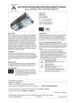
User Guide and Assembly Instructions AL2007 armature
Type: AL2007 - AL2007D - ALPL70D
AGRILIGHT b.v.
Vlotlaan 560,
2681 TX Monster
The Netherlands
Tel: +31 (0)174.287.287
Fax: +31 (0)174.287.292
Internet: www.agrilight.com
E-mail: [email protected]
IP54
Dear customer
Designated use
Thank you for buying an Agrilight b.v. product. These light fittings
were designed specifically for lighting cattle houses and meet the
requirements and specifications of the contemporary market. These
light fittings are the result of comprehensive research and clever
development and have been built in accordance with the latest
technical developments.
This manual will give you the necessary information to enable you to
safely and correctly install and use your light fittings. We advise you
to read it carefully and to keep it safe. In the event of doubt, please
do not hesitate to contact your service technician or Agrilight B.V.
for additional information.
The AL2007 light fittings are intended for lighting cattle houses. Any
other use does not comply with their designated use.
Agrilight b.v. does not accept any responsibility for damage or loss or
injury resulting from any other use than that for which the light fittings
have been developed and designed.
For your safety: Note!
Agrilight b.v. attaches the greatest importance to the light fittings being
used and maintained in a manner which gives priority to user safety.
To ensure safe and reliable use, proceed as follows:
1. Read this manual before installing the light fittings.
2. Make sure that all people involved in installing the light fittings and
putting them into use know the relevant information from this
manual before the light fittings are installed and/or put into use.
Make sure that the instructions are actually understood.
Responsibility for this rests with the person who is responsible for
installation.
Use
Since these light fittings have reflecting covers, perfect light
distribution can mostly be achieved in a cattle house of up to 24
metres wide, using a single row of light fittings in the centre of the
house. The light fittings in the AL2007 series are dust and
watertight and comply with the inspection requirements for
intensive livestock farming.
230V electric power
There is 230V live power on components in the light
fittings.
Bespoke lighting layout
A successful lighting system starts with a thoroughly devised lighting
layout with 4 light options, created specifically for your cattle house.
This advice is free of charge and obligation and takes into account any
obstacles in your cattle house to ensure that the light is uniformly
distributed throughout the house. You will be receiving this lighting
layout enclosed with our quotation.
In-line test for AL2007 light fittings
The following tests are carried out during production:
• 500 Volts test
• Earth test
• Function test
Safety instructions
Always comply with the safety instructions in this
manual. Any failure to comply with the safety
instructions, warnings and instructions may result in
serious or lethal personal injury and to material
damage to the installation.
Installation
To enable optimum performance of these light fittings it is crucial
that they are installed and put into use by a recognised installer,
in accordance with the lighting layout (installation drawing).
CE-marking
Service parts
Referring to the declaration of conformity for the
light fitting, the CE mark on the light fitting’s rating
label also confirms that the light fittings comply with
the strict European safety standards.
To ensure proper operation of the unit, only original Agrilight B.V.
components should be used, or components of the same quality.
The trigger-switch does not comprise any serviceable parts.
EU declaration of Conformity:
Manufacturer: Agrilight b.v.
Address: Vlotlaan 560, 2681 TX Monster, The Netherlands
Hereby certifies that the Agrilight B.V. armatures with type designation:
AL2007 / AL2007D / ALPL70D
comply with the provisions and regulations laid down in directive: “Low voltage”, 73/23/EEG
And comply with the standards: EN60598-1 and EN60598-2-1
Monster, 2010
Agrilight b.v.
We reserve the right to make changes to text, drawings and graphs etc. without prior notice.
Document : AL2007
Version: 02
Date: March 2010
1
The packaging contains
Unpacking and inspecting
1. Carefully unpack the AL2007 light fitting.
2. Immediately inspect it for any damage due to transport or
other causes.
3. Immediately report any damage to a light fitting to the carrier,
the insurance company and Agrilight b.v., referring to the
delivery documents. We advise you not to put a damaged
light fitting into use, even if the damage seems to be only
superficial. If you are considering putting a damaged light
fitting into use, first consult Agrilight b.v.
(figure 1)
No. Quantity Description
(1)
(2)
(3)
(4)
(5)
(6)
1
1
1
2
1
2
(7)
(8)
1
1
AL2007 light fitting
Swivel nut
Swivel plug
Suspension bracket
(for chain suspension)
Mounting bracket
(for bracket installation)
(a) 950-mm support
(for bracket installation)
(a) 450-mm support
(for bracket installation)
(a) 200-mm support
(for bracket installation)
Bulb (is supplied separately, contrary to this picture)
Wire steel light support (ALPL70D)
Other fasteners. (if and to the extent that they have been ordered)
(2)
(7)
(5)
(8)
(3)
(6a)
(6b)
(4)
(6c)
(1)
Figure 1: Contents of the packaging
An introduction to the different types of light fitting
The AL2007 series comprises three types of light fitting, each of which is available in various watt ratings (see also the Technical specifications).
• AL2007
: AL100 Watts, AL150 Watts, AL250 Watts, AL400 Watts
• AL2007D : AL100D Watts, AL150D Watts
• ALPL70D : AL70D Watts
(B)
(A)
TYPE: AL2007
TYPE: AL2007D
TYPE: ALPL70D
The AL2007 light fitting was designed specifically
for lighting cattle houses. Depending on your
requirements and the results of the lighting
layout, the light fittings have high-quality:
Type AL2007 is also available in a dim
version, identified by the letter D. This
AL2007D has been fitted with 0-10 Volt
control for this purpose.
This enables you to control the light level in
the cattle house to use between 20% and
100% of the bulbs’ power to save energy.
The ALPL70D light fittings can be dimmed
and have been designed specifically for
lighting poultry houses. The light fittings
have white 70W fluorescent bulbs with
colour code 830. The light level of this type
of bulb can be dimmed from 100% to 3% of
the bulbs’ power, which will lower their current consumption by a proportionate level.
•
high-pressure sodium bulbs
(yellow light) (A).
or
•
metal halide bulbs
(white light) (B).
Choke
AL2007D and ALPL70D light fittings have electronic chokes. This enables optimum light
level control and makes the bulb perform even better.
Technical specifications of AL2007, AL2007D and ALPL70D
Specifications
ALPL70D*
AL2007
AL70D* Watts AL100 Watts
AL150 Watts
9,70 Kg
PL
70 watts
230V / 50Hz
0,4 Amp
> 0,98
12,80 Kg
HPS of MH
150 watts
230V / 50Hz
0,76 Amp
> 0,85
Dimensions L x W x H
Weight (fully assembled)
Bulb type
Bulb power
Mains voltage**/Frequency
Current
Power factor (indicative)
*
**
2
AL250 Watts
AL2007D*
AL400 Watts AL100D* Watts AL150D* Watts
480 x 370 x 240 (mm)
D = can be dimmed via 0-10 volt control
Other voltage ratings on request.
12,40 Kg
HPS of MH
100 watts
230V / 50Hz
0,52 Amp
> 0,85
13,30 Kg
HPS of MH
250 watts
230V / 50Hz
1,30 Amp
> 0,85
14,40 Kg
HPS of MH
400 watts
230V / 50Hz
2,3 Amp
> 0,85
10,10 Kg
HPS
100 watts
230V / 50-60Hz
0,50 Amp
> 0,98
10,10 Kg
HPS
150 watts
230V / 50-60Hz
0,75 Amp
> 0,98
Installation
If the following instructions and safety
warnings are not complied with, this may
result in death or serious personal injury and
damage to the equipment.
•
•
•
•
•
Only a certified technician is permitted to install the AL2007.
Some caution is required when handling the armature, also to
prevent damage being caused to the components due to
mechanical stress. Avoid shocks and other kinds of stresses
or loads during transport, when assembling and mounting, and
when using the armature.
Always block off any traffic in the vicinity where the AL2007
is being installed before commencing with any work on the
installation.
Always disconnect the armature from the power source
before carrying out any work on the installation. Ensure that
the power supply is not turned on accidentally.
Keep the direct vicinity free from animals and any internal
transport whilst carrying out installation activities.
•
•
Only use insulated tools!
Place and secure the light in the armature before mounting the
armature.
•
Ensure that the power supply and voltage corresponds
to the power supply and voltage required by the
armature. These are clearly indicated on the armature
sticker.
•
When connecting up, consult the circuit diagram in this
manual and always ensure that you comply with the
legally applicable connecting requirements (e.g. NEN
1010 for the Netherlands).
The lighting plan shows the conditions that must be taken into
account when installing. These instructions must be fully complied
with in order to ensure uniformity and a proper illumination level.
Agrilight B.V. cannot be held liable for damage
and/or injury resulting from improper mounting
and installation.
Installing a light fitting using a mounting bracket
1. Install the bulb in the light fitting. Consult the section “Replacing bulbs” on page 4 for the work procedure.
3. Attach the two supports (6) to
2. Install the mounting bracket (5) to the ceiling,
the mounting bracket.
mounting structure or supporting beam. Properly
anchor the bracket to prevent it coming loose!
Installing a light fitting using chains
4. Push the 2 supports (6) into the slots at the top
of the light fitting (1) until the lugs click into the
support ends, locking them to prevent them
coming loose. In principle, this connection
cannot be undone again.
Levelling
(A)
1. Push the 2 suspension brackets (4) into the slots at the top of the light fitting
until the lugs click into the bracket ends, locking them to prevent them coming
loose. In principle, this connection cannot be undone again.
2. Install the chains to the ceiling, mounting structure or supporting beam.
3. Attach the light fitting by engaging the chains in the holes (A).
A spirit level vial has been installed in the plastic cover
on the electronics side of the light fitting. You can adjust
the light fitting horizontally (around the bulb axis) by
turning the light fitting around the bulb axis until the
spirit level vial is central.
Making the electrical connections
Never remove the glass cover of the light fitting,
otherwise the gasket in the cover might not seal
properly anymore. Removing the glass cover
invalidates your guarantee rights! Only carry out
assembly and disassembly work via the plastic end
covers of the light fitting.
Type AL2007 comes with a 1.5 m lead as standard
which only has to be connected in the junction box.
1. Remove the plastic end cover from the light fitting on the electronics side (2 screws).
2. Undo the two screws at the bottom of the electric slide and remove the slide from the light fitting.
3
Replacing bulbs
Always use the correct bulb in a light fitting, otherwise
the light fitting may be damaged. The correct type of
bulb is stated on the rating sticker on the light fitting.
• AL2007
bulb types: HPS of MH
(100W, 150W, 250W, 400W)
• AL2007D bulb types: HPS (100W, 150W)
• ALPL70D bulb types: PL 70W 4pin
Please be aware that both the armature glass and the
light can be very hot and cause severe burns. Leave
the light to cool down for at least half an hour before
removing and handling.
The armature glass must never be detached or removed
as this will cause damage to the sealing. The warranty
becomes invalid if the armature glass is detached or
removed. A lamp may only be removed or inserted through
the opening in the side of the light compartment. This
opening can be accessed only when the plastic cover is
detached.
Before replacing the bulb interrupt the power supply to
the light fitting to ensure a safe work situation.
Do not touch the bulb with your bare hands but wear
clean gloves. This way you prevent the bulb glass being
polluted and dirt burning into the glass.
Removing the end cover
1. Remove the two Torx screws from the plastic cover of the light compartment using a Torx (T20) screwdriver.
2. Use the two tabs to release and remove the cover. In the resulting opening there is a reflector with a rectangular window which
provides manual access to the light.
Installing / replacing bulbs of AL2007 and AL2007D light fittings
Carefully turn the bulb in an anti-clockwise direction to unscrew it
and screw the new bulb into the light fitting in the opposite
direction until it is finger-tight. Make sure you do not deform the
reflector plates while replacing bulbs.
After installing the bulb, we recommend carefully centring it in
respect of the reflector / bulb axis by hand.
The slight lateral clearance of the bulb in the fitting can be used
for this.
Slightly pushing the glass of the bulb from the side should suffice.
Installing / replacing bulbs/lamp support of ALPL70D light fittings
The fluorescent light (PL) is provided with a steel wire light support that supports the ends of the fluorescent light. This ensures the
‘straight and horizontal’ insertion and support of the fluorescent light in relation to the reflector assembly.
The lampbrace is designed to support both the fluorescent tubes of General Electric (three fold lamp) and Osram (four fold lamp).
Replacing bulb / lamp support
1. Lamp replacement: remove the steel wire light support mounted between the reflector wings and remove the light by carefully pulling it
straight out of the fitting. Make sure that the reflector parts are not distorted in any way as these are essential for ensuring a proper
and optimum distribution of light.
2. Fit the light into position by inserting it straight and horizontally into the light fitting.
3. Mount the steel wire supports of the light by sliding it carefully into the light glass and whilst sliding it into position at both ends of the
reflector wings. Slide the light support into position within a distance of approx. 4-6 cm from the end of the light (see photos below)
and at right angles to the length of the light. Make sure that the reflector parts are not distorted in any way as these are essential for
ensuring a proper and optimum distribution of light.
Restoring the end cover
4 - 6 cm
1. Clean the contact surfaces of the armature and the cover using a mild detergent on a damp cloth. Inspect the rubber sealing and
gasket and replace if necessary.
2. Rub some mild soap or acid-free vaseline onto the rubber sealing and gasket. This will enable the cover to be fitted more easily.
3. Close the armature by replacing the cover and by screwing the two Torx screws tightly into position. To prevent damage to the cover
or to the sealing do not use a battery-powered device to do this, nor apply excessive force. When closed, the cover should fit just
inside the rim of the aluminium armature housing.
Maintenance
Always remove the voltage from the light fitting before carrying out maintenance work on the light fitting!
Pollution may negatively affect the service life of the light fitting. To maintain optimum light output we recommend regularly checking the
state of the bulbs and cleaning the light fitting. A special cleaning kit is available for the AL2007 light fittings, consisting of a rounded brush,
a telescopic bar, a customised bucket and special detergent. For additional information or to order this cleaning kit, contact your installer or
Agrilight b.v.
4
Malfunction
When checking malfunctions, be aware of the
risk of electrically live components. Although the
armatures are designed with safety in mind and
are earthed, hazards due to malfunctions can
never be ruled out. Only certified technicians are
permitted to handle the electrical installation or to
perform measurements on the unit.
Always disconnect the armature before opening
the plastic cover (turn off the main switch and
secure it, e.g. with the use of a padlock).
Be aware of and prevent any accidental
activation by others or by an automated control
and/or dimmer switch. In the event of a
malfunction, never touch the armature whilst the
power supply is still connected or if the casing of
the armature is damaged or wet.
The light fitting does not work:
Check that there is mains voltage:
• Check the switch panels;
• Check the fuses;
• Check your computer settings (if computer-controlled);
• Check / replace the bulb.
Check to determine whether the bulb has reached the end of its
lifecycle:
• The bulb is flashing on and off;
• The end of the bulb is starting to turn black;
• Brown discoloration on the glass of the bulb;
If the bulb does not work: replace the bulb as soon as possible or
disconnect the light fitting from its power supply.
If the bulb still does not work:
• Check the wiring;
• Replace the starter if the light fitting still does not work;
• Replace the ballast resistor if the light fitting still does not work.
Note! Light fittings which can be dimmed (D) have no loose starters or
capacitors. Replace the ballast resistor unit if the new bulb does not
work.
CONDITIONS OF WARRANTY
General
1. If it appears that your product does not function well, even though you have used it in the correct manner and in accordance with
the user manual and assembly instructions, the product will be replaced free of charge within a period of one year after
purchase. In order to claim this warranty the customer must submit the product invoice to Agrilight B.V. with the 1 year warranty
period.
2. The product must be returned to Agrilight B.V. within 30 days following the occurrence of the defect or malfunction for the
purpose of verification.
3. The product must be provided with a project name and sent to the following address:
Agrilight b.v.
Attn.: Service Dept.
Vlotlaan 412
2681 TV Monster, The Netherlands
4. When Agrilight B.V. sends the replacement parts you will receive an invoice that will be credited to your account when and if it
can be verified that the malfunction of defect is covered by the warranty.
5. If Agrilight B.V. has not received the defective product by return mail within 30 days of the invoice date, the warranty invoice will
be treated as a sales invoice, after which period the invoiced amount must be paid to Agrilight B.V. within 30 days.
6. The warranty does not cover the following situations for which the customer will be invoiced during the warranty period:
a. Defects or damage resulting from fire, earthquakes, floods, lightning strikes, other natural disasters, as well as
environmental pollution and problems related to power supply.
b. Defects resulting from sand, mud, dirt etc. entering the cabinet of the product.
c. Defects resulting from transport, accidents, shock and vibrations etc. following the purchase from and delivery of the
product by Agrilight B.V..
d. Defects resulting from carelessness or incorrect storage, improper maintenance etc.
e. Defects resulting from improper use (such as the use of the unit for purposes not listed in the user manual and/or assembly
instructions etc.).
f . Defects resulting from (uncertified) repairs and modifications.
g. If the invoice cannot be submitted together with the product when warranty claims are made.
h. If changes have been made to the original purchase invoice or to the customer name on the invoice.
7. The liability on the part of Agrilight B.V. is limited to the scope of this warranty and only includes the replacement and/or repair of
the product. Agrilight B.V. accepts no liability for damages incurred directly or indirectly as a result of any defects in the product.
Agrilight B.V. is not liable for expenses incurred as a result of disassembly and assembly/mounting, or expenses incurred as a
result of travel and accommodation.
8. Any damage resulting from transport or incomplete delivery must be reported to Agrilight B.V. within 5 working days. Any
notifications received by Agrilight B.V. beyond this period do not fall within the scope of the warranty or warranty period.
Warranty on the lights
1.
2.
3.
4.
A warranty period of 1 year applies to the lights of armatures supplied by Agrilight B.V.
This warranty applies only to normal use and normal operating conditions with regard to power/voltage and frequency.
In the case of all lights supplied by Agrilight B.V. account must taken of approx. 1% failure per 1000 lighting hours.
Lights that fail prematurely during the course of the warranty period will be replaced by Agrilight B.V. Lights that fail as a result of
abnormal external effects, due to breakage of the exterior bulb following thermo-shock or due to theft, do not fall under the
replacement warranty.
5. The warranty does not apply to failure of the lights applied to systems in which those light types were used if such a system is
not in compliance with IEC standards and requirements.
Aging and tolerances in the intensity of the lights applied
The light will age during use and will eventually emit less light as the number of total life-cycle lighting hours increases.
The drop in light intensity is increased by a voltage that exceeds the prescribed rated power.
LIABILITY
Agrilight B.V. states emphatically that it cannot be held liable for damages of any kind or magnitude, caused by non-compliance with
the instructions in this manual or as a result of non-compliance with the connecting and installing requirements according to NEN
1010. We also refer to our terms and conditions of delivery according to the conditions and requirements laid down by the
Netherlands Metal Association and any additional warranty provisions of Agrilight B.V.
We reserve the right to make amendments without further notification.
User Guide and Assembly Instructions AL2007 armature
Type: AL2007 - AL2007D - ALPL70D
VSA
C
VSA:
C:
I:
B.H.:
Ballast resistor / Choke
Capacitor
Ignition / Starter
Bulb holder
I
* The white wire must be
connected to the 230V
output of the VSA (choke)
on all bulb versions.
AL2007 (100W, 150W, 250W, 400W)
EVSA
EVSA: Ballast resistor / Choke
B.H.: Bulb holder
Dimmer
AL2007D (100W, 150W)
EVSA
EVSA: Ballast resistor / Choke
B.H.: Bulb holder
Dimmer
ALPL70D (70W)
6