1
Sun Fire™ V20z and Sun Fire V40z
Servers
Troubleshooting Techniques and
Diagnostics Guide
Sun Microsystems, Inc.
www.sun.com
Part No. 817-7184-12
July 2005, Revision 01
Submit comments about this document at: http://www.sun.com/hwdocs/feedback
Copyright 2005 Sun Microsystems, Inc., 4150 Network Circle, Santa Clara, California 95054, U.S.A. All rights reserved.
Sun Microsystems, Inc. has intellectual property rights relating to technology that is described in this document. In particular, and without
limitation, these intellectual property rights may include one or more of the U.S. patents listed at http://www.sun.com/patents and one or
more additional patents or pending patent applications in the U.S. and in other countries.
This document and the product to which it pertains are distributed under licenses restricting their use, copying, distribution, and
decompilation. No part of the product or of this document may be reproduced in any form by any means without prior written authorization of
Sun and its licensors, if any.
Third-party software, including font technology, is copyrighted and licensed from Sun suppliers.
Parts of the product may be derived from Berkeley BSD systems, licensed from the University of California. UNIX is a registered trademark in
the U.S. and in other countries, exclusively licensed through X/Open Company, Ltd.
Sun, Sun Microsystems, the Sun logo, Java, AnswerBook2, docs.sun.com, and Solaris are trademarks or registered trademarks of Sun
Microsystems, Inc. in the U.S. and in other countries.
All SPARC trademarks are used under license and are trademarks or registered trademarks of SPARC International, Inc. in the U.S. and in other
countries. Products bearing SPARC trademarks are based upon an architecture developed by Sun Microsystems, Inc.
The OPEN LOOK and Sun™ Graphical User Interface was developed by Sun Microsystems, Inc. for its users and licensees. Sun acknowledges
the pioneering efforts of Xerox in researching and developing the concept of visual or graphical user interfaces for the computer industry. Sun
holds a non-exclusive license from Xerox to the Xerox Graphical User Interface, which license also covers Sun’s licensees who implement OPEN
LOOK GUIs and otherwise comply with Sun’s written license agreements.
U.S. Government Rights—Commercial use. Government users are subject to the Sun Microsystems, Inc. standard license agreement and
applicable provisions of the FAR and its supplements.
DOCUMENTATION IS PROVIDED "AS IS" AND ALL EXPRESS OR IMPLIED CONDITIONS, REPRESENTATIONS AND WARRANTIES,
INCLUDING ANY IMPLIED WARRANTY OF MERCHANTABILITY, FITNESS FOR A PARTICULAR PURPOSE OR NON-INFRINGEMENT,
ARE DISCLAIMED, EXCEPT TO THE EXTENT THAT SUCH DISCLAIMERS ARE HELD TO BE LEGALLY INVALID.
Copyright 2005 Sun Microsystems, Inc., 4150 Network Circle, Santa Clara, Californie 95054, Etats-Unis. Tous droits réservés.
Sun Microsystems, Inc. a les droits de propriété intellectuels relatants à la technologie qui est décrit dans ce document. En particulier, et sans la
limitation, ces droits de propriété intellectuels peuvent inclure un ou plus des brevets américains énumérés à http://www.sun.com/patents et
un ou les brevets plus supplémentaires ou les applications de brevet en attente dans les Etats-Unis et dans les autres pays.
Ce produit ou document est protégé par un copyright et distribué avec des licences qui en restreignent l’utilisation, la copie, la distribution, et la
décompilation. Aucune partie de ce produit ou document ne peut être reproduite sous aucune forme, par quelque moyen que ce soit, sans
l’autorisation préalable et écrite de Sun et de ses bailleurs de licence, s’il y en a.
Le logiciel détenu par des tiers, et qui comprend la technologie relative aux polices de caractères, est protégé par un copyright et licencié par des
fournisseurs de Sun.
Des parties de ce produit pourront être dérivées des systèmes Berkeley BSD licenciés par l’Université de Californie. UNIX est une marque
déposée aux Etats-Unis et dans d’autres pays et licenciée exclusivement par X/Open Company, Ltd.
Sun, Sun Microsystems, le logo Sun, Java, AnswerBook2, docs.sun.com, et Solaris sont des marques de fabrique ou des marques déposées de
Sun Microsystems, Inc. aux Etats-Unis et dans d’autres pays.
Toutes les marques SPARC sont utilisées sous licence et sont des marques de fabrique ou des marques déposées de SPARC International, Inc.
aux Etats-Unis et dans d’autres pays. Les produits portant les marques SPARC sont basés sur une architecture développée par Sun
Microsystems, Inc.
L’interface d’utilisation graphique OPEN LOOK et Sun™ a été développée par Sun Microsystems, Inc. pour ses utilisateurs et licenciés. Sun
reconnaît les efforts de pionniers de Xerox pour la recherche et le développement du concept des interfaces d’utilisation visuelle ou graphique
pour l’industrie de l’informatique. Sun détient une license non exclusive de Xerox sur l’interface d’utilisation graphique Xerox, cette licence
couvrant également les licenciées de Sun qui mettent en place l’interface d ’utilisation graphique OPEN LOOK et qui en outre se conforment
aux licences écrites de Sun.
LA DOCUMENTATION EST FOURNIE "EN L’ÉTAT" ET TOUTES AUTRES CONDITIONS, DECLARATIONS ET GARANTIES EXPRESSES
OU TACITES SONT FORMELLEMENT EXCLUES, DANS LA MESURE AUTORISEE PAR LA LOI APPLICABLE, Y COMPRIS NOTAMMENT
TOUTE GARANTIE IMPLICITE RELATIVE A LA QUALITE MARCHANDE, A L’APTITUDE A UNE UTILISATION PARTICULIERE OU A
L’ABSENCE DE CONTREFAÇON.
Please
Recycle
Contents
Preface
xi
Before You Read This Document
Using UNIX Commands
xi
xi
Typographic Conventions
Related Documentation
xii
xii
Documentation, Support, and Training
Third-Party Web Sites
xiii
Sun Welcomes Your Comments
1.
Preventive Maintenance
Guidelines for Success
Managing Change
xiv
1
1
2
Visually Inspecting Your System
3
External Visual Inspection
3
Internal Visual Inspection
3
Troubleshooting Dump Utility
2.
Diagnostics
xiii
4
7
SP-based Diagnostics
8
How to Start SP-based Diagnostics
8
Contents
iii
CD-Based Diagnostics
9
Installing and Running CD-Based Diagnostics
BIOS Version 2.2.0.0 and Later
Earlier BIOS Versions
9
10
10
Installation of CD-Based Diagnostics
10
Running CD-Based Diagnostics from the Options Menu
11
Menu Options 11
Remote Access to CD-Based Diagnostics
Available Diagnostics Tests and Modules
Running Diagnostic Tests
Test Results
15
17
Saving Test Results
19
SP-based Diagnostics
19
CD-Based Diagnostics Tests
Stopping Tests
19
19
Troubleshooting Topics
BIOS
21
21
BIOS Error or Warning Events
BIOS POST Codes
Boot Issues
DIMM Faults
ECC Errors
Inventory
24
25
26
27
29
Lights, LCD, LED
Log Files
21
25
Clear CMOS Jumper
30
30
Machine Check Error
iv
14
16
Sample Output
3.
12
31
Sun Fire V20z and Sun Fire V40z Servers Troubleshooting Techniques and Diagnostics Guide • July 2005
Network Connectivity
32
Network Share Volume
Operating System
Operator Panel
33
33
33
Illuminated, Readable Text, Non-working Buttons
Illuminated, Unreadable Text
Illuminated, No Text
No Illumination
34
34
34
PCI or PCI-X Hot-plugs
35
Platform OS Does not Boot
PPCBoot - Bad CRC Error
Restore Default Settings
36
37
38
SCSI Configuration Utility
39
RAID Properties Menu Item Disabled
IM Volume Uses Extra SCSI ID
39
39
Configuration Utility Disables Selection of Disk
Service Processor
40
41
‘Booting SP . . . ’ Displays on Operator Panel
Continuous Boot of SP
Failure to Boot
43
Via the SP
43
Failure to Boot after Downgrade
44
45
Failure to Retain User Accounts and Settings
Mount to Network Share Volume
Persistent Storage Issues
SSH Script Hangs
41
42
Via a PC Attached to the Serial Port
Update Failed
33
45
46
46
47
47
Contents
v
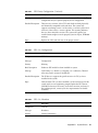
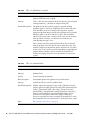
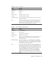
System Events
47
Thermal Trip Events
48
VRM Crowbar Assertions
A.
Diags Test Results
Test Descriptions
Voltage
49
51
51
52
Voltage Trimming
Voltage Read
Test Results
52
52
53
Non-Trim Voltage Passed
Trim Voltage Passed
53
53
Voltage Exceeds Limit Failure
Hardware Failure
Fan
54
54
Fan Controller Programming
Test Results
55
Fans Passed
55
High Speed Failure
56
Low Speed Failure
57
Memory
54
59
March Test
59
RandAddr Test
Retention Test
Test Results
59
59
60
Memory Tests Passed
Service Failure
ECC Failure
60
61
61
BIOS Setting Failure
vi
53
61
Sun Fire V20z and Sun Fire V40z Servers Troubleshooting Techniques and Diagnostics Guide • July 2005
NIC
63
Test Results
63
NIC Passed
63
Service Failure
64
Link Down Failure
64
Link Setting Mismatch Failure
Link Status Unknown Failure
Loopback Failure
Write Failure
65
Read Failure
65
64
64
Comparison Failure
Storage
64
65
66
Test Results
66
Storage Passed
66
Device Does Not Recognize Self-test Command Failure
Device Cannot Process Self-test Command Failure
Self-test Failure
66
67
Self-test Corruption Failure
Flash Memory
66
67
68
Test Results
68
Flash Memory Passed
68
Open System Failure
68
Read System Failure
68
Access Device Failure
Write System Failure
Erase Failure
69
69
69
Magic Number Failure
69
Data Comparison Failure
70
Contents
vii
LED
70
Test Results
70
LED Passed
70
Device Not Present Warning
Read Failure
72
Write Failure
72
Temperature
72
73
Test Results
73
Temperature Passed
73
Reading Exceeds Warning Threshold Passed
Device Not Present Warning
Read Failure
74
74
Reading Exceeds Critical Threshold Failure
Operator Panel
75
Test Results
75
OpPanel Passed
75
Write Failure
75
Data Comparison Failure
Power Passed
76
76
Power Good Failure
Read Failure
C.
System Events
75
76
Test Results
B.
74
75
Read Failure
Power Supply
73
77
78
79
Event Details
79
POST Codes
103
Contents
viii
POST Codes for Phoenix BIOS
103
POST Codes for Boot Block in Flash ROM
D.
Glossary
109
111
Contents
ix
x
Sun Fire V20z and Sun Fire V40z Servers Troubleshooting Techniques and Diagnostics Guide • July 2005
Preface
The Sun Fire V20z and Sun Fire V40z Servers—Troubleshooting Techniques and
Diagnostics Guide provides information about and solutions for system problems that
customers might encounter. It includes instructions for use of the diagnostics tests
and detailed explanations of all system events. This document is written for
technicians, system administrators, authorized service providers (ASPs), and users
who have advanced experience troubleshooting and replacing hardware.
Before You Read This Document
Some troubleshooting procedures require the removal and replacement of system
components. Therefore, it is important that you review the safety guidelines and
component removal and replacement procedures in these documents:
■
Sun Fire V20z and Sun Fire V40z Servers Safety and Compliance Guide
■
Sun Fire V20z and Sun Fire V40z Servers User Guide
Using UNIX Commands
This document might not contain information about basic UNIX® commands and
procedures such as shutting down the system, booting the system, and configuring
devices. Refer to the following for this information:
■
Software documentation that you received with your system
■
Solaris™ Operating System documentation, which is at:
http://docs.sun.com
xi
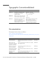
Typographic ConventionsRelated
Typeface*
Meaning
Examples
AaBbCc123
The names of commands, files,
and directories; on-screen
computer output
Edit your.login file.
Use ls -a to list all files.
% You have mail.
AaBbCc123
What you type, when contrasted
with on-screen computer output
% su
Password:
AaBbCc123
Book titles, new words or terms,
words to be emphasized.
Replace command-line variables
with real names or values.
Read Chapter 6 in the User’s Guide.
These are called class options.
You must be superuser to do this.
To delete a file, type rm filename.
* The settings on your browser might differ from these settings.
Documentation
The documents listed as online are available at:
http://www.sun.com/products-nsolutions/hardware/docs/Servers/Workgroup_Servers/Sun_Fire_V20z/
index.html
xii
Application
Title
Part Number
Safety information
Important Safety Information for Sun Hardware
Systems
816-7190-xx
Safety notices and
international compliance
certification statements
Sun Fire V20z and Sun Fire V40z Servers—Safety
and Compliance Guide
817-5251-xx
Hardware and system
software installation
Sun Fire V20z and Sun Fire V40z Servers—
Installation Guide
817-5246-xx
Maintenance procedures
and other information
Sun Fire V20z and Sun Fire V40z Servers—User
Guide
817-5248-xx
Operating-system
installation
Sun Fire V20z and Sun Fire V40z Servers—Linux
Operating System Installation Guide
817-5250-xx
Sun Fire V20z and Sun Fire V40z Servers Troubleshooting Techniques and Diagnostics Guide • July 2005
Application
Title
Part Number
Troubleshooting and
diagnostics
Sun Fire V20z and Sun Fire V40z Servers—
Troubleshooting Techniques and Diagnositcs Guide
817-7184-xx
Late-breaking
information
Sun Fire V20z and Sun Fire V40z Servers Release
Notes
817-1771-xx
Comparison of server
models
Differences Between Versions of the Sun Fire V20z
and Sun Fire V4z Servers
817-7185-xx
Documentation, Support, and Training
Sun Function
URL
Description
Documentation
http://www.sun.com/documentation/
Download PDF and HTML documents,
and order printed documents
Support and
Training
http://www.sun.com/supportraining/
Obtain technical support, download
patches, and learn about Sun courses
Third-Party Web Sites
Sun is not responsible for the availability of third-party web sites mentioned in this
document. Sun does not endorse and is not responsible or liable for any content,
advertising, products, or other materials that are available on or through such sites
or resources. Sun will not be responsible or liable for any actual or alleged damage
or loss caused by or in connection with the use of or reliance on any such content,
goods, or services that are available on or through such sites or resources.
Preface
xiii
Sun Welcomes Your Comments
Sun is interested in improving its documentation and welcomes your comments and
suggestions. You can submit your comments by going to:
http://www.sun.com/hwdocs/feedback
Please include the title and part number of your document with your feedback:
Sun Fire V20z and Sun Fire V40z Servers Troubleshooting Techniques and Diagnostics
Guide, part number 817-7184-12
xiv
Sun Fire V20z and Sun Fire V40z Servers Troubleshooting Techniques and Diagnostics Guide • July 2005
CHAPTER
1
Preventive Maintenance
Many problems can be avoided with careful system setup, comprehensive change
management, and adherence to established, repeatable procedures.
Guidelines for Success
Below are some guidelines that can help you prevent problems and simplify
troubleshooting.
■
Use uniform naming conventions for your servers, such as names that denote
server locations.
■
Use unique IDs or names for your devices to lessen the risk of competition for the
same resource. Use the server setup utility to check for possible conflicts.
■
Create a backup plan.
■
■
If data changes frequently, schedule backups to occur frequently.
■
Maintain a library of backups, based on your information restoration needs.
■
Periodically test your backups to ensure that your data is stored correctly.
Use enterprise systems management tools to automate certain processes, or
manually track this information:
■
Periodically check hard disk space. Ensure that each hard drive has a
minimum of 15 percent free space.
■
Keep historical data. For example, a baseline record of initial CPU use levels
ensures that you will be aware of significant increases. If problems occur, you
can compare the baseline and current data. Other things you might track
include user, bus, and power utilization rates.
■
Maintain a trend analysis to account for predictable changes. For example, if
the CPU utilization rate always increases by 50 percent during late morning,
you can assume that the increase is normal for that server.
1
■
Create a problem resolution notebook. If a problem occurs, keep a log of the
actions you took to resolve it. In the future, the information in the log can help
you or someone else solve the same problem more quickly. This information
also can ensure accuracy in any part replacement issue.
■
Keep an updated network topology map in an accessible location. This map
can help troubleshooting efforts for networking problems.
Managing Change
Most server problems occur after something in the server changes. When you make
changes to your server, follow these guidelines:
■
Document the system settings before the change.
■
If possible, make one change at a time, in order to isolate potential problems. In
this way, you can maintain a controlled environment and reduce the scope of
troubleshooting.
■
Take note of the results of each change. Include any errors or informational
messages.
■
Check for potential device conflicts before you add a new device.
■
Check for version dependencies, especially with third-party software.
■
To find and fix the cause of a server problem, collect information about:
■
2
■
Events that occurred prior to the failure.
■
Whether any hardware or software was modified or installed.
■
Whether the server recently was installed or moved.
■
How long the server exhibited symptoms.
■
The duration or frequency of the problem.
After you assess the problem and note your current configuration and
environment:
■
Visually inspect your system (see below).
■
Execute diagnostics tests (see “Diagnostics” on page 37).
Sun Fire V20z and Sun Fire V40z Servers Troubleshooting Techniques and Diagnostics Guide • July 2005
Visually Inspecting Your System
Improperly set controls and loose or improperly connected cables are common
causes of problems with hardware components. When you investigate a system
problem, first check all the external switches, controls, and cable connections. If this
does not resolve your problem, then visually inspect the system’s interior hardware
for problems such as a loose card, cable connector, or mounting screw.
See the Sun Fire V20z and Sun Fire V40z Servers User Guide for information about how
to remove and replace hardware components.
External Visual Inspection
To perform a visual inspection of the external system:
1. Inspect the status indicators that can indicate component malfunction. See
“Lights, LCD, LED” on page 64.
2. Verify that all power cables are properly connected to the system, the monitor, and
the peripherals, and check their power sources.
3. Inspect connections to any attached devices (network cables, keyboard, monitor,
mouse) and any devices that are attached to the serial port.
Internal Visual Inspection
Note – Before you continue, read the instructions in the document Important Safety
Information about Sun Hardware Systems, which is shipped with your system. Also
review the instructions for removal and replacement of components in your Sun Fire
V20z and Sun Fire V40z Servers User Guide.
You can use the System Status screen in the SM Console to identify status
information of all system hardware components and sensors. This System Status
screen simplifies the search for components that have problems or for failed
components that must be replaced. The component images that display in the
System Status screen represent the actual hardware components and their
approximate locations and sizes. See the Systems Management Guide for more
information.
1. To perform a visual inspection of the internal system, power off the system.
Chapter 1
Preventive Maintenance
3
2. Disconnect all power cables from electrical outlets. (Some servers have two power
supplies and two power cables. Ensure that both are disconnected from electrical
outlets.)
Caution – When you unplug the AC power cords from the power supplies, system
ground is also removed. To avoid electrostatic discharge damage to the machine,
you must maintain an equal voltage potential to the machine. Ensure that you wear
ESD protection, such as an ESD wrist strap, during all procedures in which you
touch components in the system, and during removal and replacement procedures.
3. Remove the server cover (follow the procedures in the user guide for your server).
Caution – Some components can become hot during system operations. Allow
components to cool before you touch them.
4. Remove components, if necessary, and verify that sockets are clean.
5. Replace components and verify that they are firmly seated in their sockets or
connectors.
6. Check all cable connectors inside the system to verify that they are firmly and
correctly attached to their appropriate connectors.
7. Replace the server cover.
8. Reconnect the system and any attached peripherals to their power sources.
9. Power on the server and the attached peripherals.
Troubleshooting Dump Utility
Note – The Troubleshooting Dump Utility also is discussed in the Sun Fire V20z and
Sun Fire V40z Servers—Server Management Guide, including command syntax,
arguments, and returns.
The Troubleshooting Dump Utility (TDU) captures important platform OS and
service processors (SP) debug data. When you execute this command, this data is
gathered and stored in the specified nfs directory in tar format or sent to stdout,
depending on the command option you choose. Along with the log file, TDU creates
4
Sun Fire V20z and Sun Fire V40z Servers Troubleshooting Techniques and Diagnostics Guide • July 2005
a summary log file that contains the detail of whether or not TDU successfully
gathered each requested piece of information. The summary log file is included in
the tar file.
Key TDU definitions are:
■
GPR - General Purpose Registers.
■
MCR - Machine Check Registers.
■
MSR - Machine Status Registers, including the MCRs.
■
SPR - Special Purpose Registers.
■
CSR - PCI Configuration Space Registers.
■
TCB - Trace Buffers from K-8.
■
TMB - Trace Buffers (TCB) from DRAM
The following data is captured by default:
■
SST data (5KB).
■
Uncleared current events (120KB).
■
Software Inventory (approximately 25KB).
■
Hardware Inventory (approximately 25KB).
■
pstore data:
■
■
Group file (approximately 0.5KB)
■
Event configuration file (evcfg, approximately 4KBb).
■
Security configuration file (seccfg, approximately 5KB).
■
Ethernet configuration file (netifcfg2-eth0, approximately 0.2KB).
Current processes on the Service Processor (10KB).
Optionally, the TDU can capture the following data:
■
K-8 registers (-c|--cpuregs), including GPRs, SPRs, MSRs, MCRs and TCB
(19KB).
■
All PCI configuration registers (-p|--pciregs) (25KB).
■
TCB from DRAM (--tmb, 128KB by default or user-defined size up to1GB).
Note – Storage of 1 KB of TMB in text mode takes about 4K on disk. Storage of
32KB of default TMB takes 128 KB and storage of 128 MB of TMB takes about 1GB of
disk space.
To run the Troubleshooting Dump Utility, use this command:
sp get tdulog
Chapter 1
Preventive Maintenance
5
When you specify the -f option, the captured data is gathered and stored on the SP
in a compressed tar file. The Troubleshooting Dump Utility can take up to 15
minutes to run. The system prompt displays when it is complete.
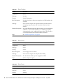
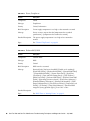
Every server management command returns a code when it completes. Below are
two return codes, their IDs, and brief descriptions.
Return
ID
Definition
NWSE_Success
0
Command completed successfully.
NWSE_InvalidUsage
1
Invalid usage: bad parameter usage, conflicting options
specified.
Note – Return code IDs are decimal numbers.
6
Sun Fire V20z and Sun Fire V40z Servers Troubleshooting Techniques and Diagnostics Guide • July 2005
CHAPTER
2
Diagnostics
Diagnostics are a set of tests that determine the health of the hardware in your Sun
Fire V20z server or Sun Fire V40z server. The diagnostics tests that are included with
the server check the platform and the SP.
Diagnostics tests:
■
Test and verify hardware functionality. For example, “fan failed to reach target
speed.”
■
Indicate and isolate device failures. For example: “device not present.”
■
Isolate hardware or software problems as diverse as voltage levels or the SP’s
read and write flash files.
■
Identify replaceable parts. (Instructions for removing and replacing parts are in
the Hardware Components and Service document.)
You can run diagnostics tests in either of two ways.
■
SP-based diagnostics, detailed below, run via the SP.
■
CD-based diagnostics, explained on page 9, run via a diagnostics CD.
Note – While you run diagnostics on your server, do not interact with the SP
through the command-line interface of IPMI. The values returned by the sensors are
not reliable in this case. Sensor commands that are issued while diagnostics are
loaded might result in the logging of false critical events in the events log.
Specific tests are designed to run on the SP and other tests are designed to run on
the platform OS. See “Diagnostics Modules” on page 14, for more information.
7
SP-based Diagnostics
You can run diagnostics tests from the SP. The diagnostics files are included in the
Network Share Volume (NSV) directory. If you choose to run SP-based diagnostics
tests:
■
You can run tests on either the SP or on the platform. (See Table 3-1, “Diagnostics
Modules” on page 45 for more information.)
■
You can run tests on the SP, only.
■
You can run the tests remotely.
■
You can save test results in the external (NSV) location, if the NSV is mounted.
See the Sun Fire V20z and Sun Fire V40z Servers—Installation Guide for information
about how to set up the SP, how to install and configure the NSV software, and how
to use SSH scripting. See the Sun Fire V20z and Sun Fire V40z Servers—Server
Management Guide for information about how to update the diagnostics tests.
Note – The diagnostics version that is in the NSV must be the same as the version
that is installed on the SP.
How to Start SP-based Diagnostics
1. To enable both SP and platform diagnostic tests, execute the command, diags
start. This command reboots the platform into diagnostics mode. Wait at least
two or three minutes before you attempt to run the tests.
or
To enable only SP diagnostics tests without rebooting the platform, execute the
command diags start –n.
Note – For CD-based diagnostics, the -n argument specifies: Do not load the SP
with diagnostics.
2. To determine if the diagnostics tests are available to run, execute the command
diags get state. The command returns one of these states:
8
Sun Fire V20z and Sun Fire V40z Servers Troubleshooting Techniques and Diagnostics Guide • July 2005
Success Text Message
The SP and the platform diagnostics systems are available to receive
test requests.
or
Error Text Message
The platform diagnostics system is not available.
See “Diagnostics Modules” on page 14, for a table of diagnostics modules and the
types of tests that they contain. The table indicates whether each test module runs
on the SP or on the platform.
CD-Based Diagnostics
Note – It is possible to run platform-only tests on a previous release of the NSV
(earlier than 2.x.x.x), but the user must manually disable interleaving to run memory
tests. It is not possible to run SP tests from the CD with these earlier releases of the
NSV.
■
You can run diagnostics tests from a CD. These options are available:
■
You can run tests on either the SP or on the platform.
■
You can run tests on the platform, only.
■
After you boot the CD, you can run the tests remotely—use SSH to log on to the
diagnostics tests.
■
You can save test results to a USB stick or a floppy disk.
Installing and Running CD-Based Diagnostics
BIOS does not, by default, boot into diagnostics mode. If the CD is installed in the
server when the system boots and if the CD drive is first in the boot order, BIOS
detects the CD and reboots in diagnostics mode. To accomplish this, follow the
instructions, below.
Chapter 2
Diagnostics
9
BIOS Version 2.2.0.0 and Later
In BIOS versions 2.2.0.0 and later, you can set up BIOS to boot into the diagnostics
mode. Then, during boot, the CD detects the BIOS setting and reboots the machine
into diagnostics mode, if necessary. This is an option in the BIOS Advanced Menu.
See the BIOS Configuration information in the Sun Fire V20z and Sun Fire V40z
Servers—User Guide, for information about how to suppress the reboot.
Earlier BIOS Versions
If your BIOS version cannot boot in diagnostic mode (this information is detected on
boot), the system displays a set of steps that the user can follow to configure the
BIOS settings and to successfully run the memory tests. (If the settings are incorrect,
the memory tests print warnings.)
Installation of CD-Based Diagnostics
To ensure that the CD boots automatically, it must be first in your server’s boot
sequence. The boot sequence is established in the BIOS Boot menu. You can alter the
sequence as noted, below:
■
In the BIOS Boot menu, use the plus (+) or minus (-) to move the CD-ROM drive
to the top of the list. For more information, see the Sun Fire V20z and Sun Fire
V40z Servers—User Guide.
■
If the server boots from the hard disk drive, remove the HDD.
■
If the server boots from a PXE server, disconnect the Ethernet cables.
1. See your system vendor for the location of the ISO image:
cd_diags.iso
2. Burn the ISO image onto a CD.
3. Insert the CD into the drive and boot the platform. (The CD drive must be first on
the boot list, in order for this to occur automatically. See the bullet points, above,
to ensure this.)
When the CD has booted, the platform IP address displays:
Welcome to CD Diagnostics <version displayed>.
Platform eth0 connected for SSH sessions at <ipaddr>
Platform eth1 connected for SSH sessions at <ipaddr>
You can use this IP address if you want to SSH remotely. See “Remote Access to CDBased Diagnostics” on page 43. You are logged on automatically as the user
diagUser.
10
Sun Fire V20z and Sun Fire V40z Servers Troubleshooting Techniques and Diagnostics Guide • July 2005
As soon as the CD boot process is complete, you are logged on and the CD
diagnostics menu displays on your screen. You can use the menu options to run tests
and capture system information, or you can use the command line.
Running CD-Based Diagnostics from the Options Menu
The options menu simplifies the process of running a full set of diagnostics tests and
capturing system information on a floppy or USB storage device.
Menu Options
1. View Documentation - Use this option to open the documentation. This online
documentation explains:
■
all the menu options
■
helpful tips
■
known issues
■
commands you can run from the command line
■
instructions for using SSH from a remote machine
■
other important information
2. Create script run_commands.sh – Use this option to run tests and save system
information in a log file. This option opens a series of three prompts. When you
select the prompts, a script is created and stored in the same location as the saved
log file. You can use it to run operations on multiple machines.
3. Run script run_commands.sh - Use this option to run a script that you saved to a
floppy disk.
4. Go to Command Line Interface - Use this option to go to the command line
interface. See the Sun Fire V20z and Sun Fire V40z Servers—Server Management
Guide for more information.
5. Shutdown System - Use this option to terminate diagnostics tests and shut down
the OS.
Note – For detailed information, select View Documentation.
Chapter 2
Diagnostics
11
Remote Access to CD-Based Diagnostics
Remote access requires the prior creation of a manager-level user on the platform.
See the Sun Fire V20z and Sun Fire V40z Servers—Server Management Guide for
instructions.
To use a remote command-line interface for CD-based diagnostics tests, via SSH
network access:
1. SSH to the platform IP address as the user: setup.
If you already created a manager-level user on the SP, you are prompted for a
username and password to create a new account. You can use any username except
one of these:
diagUser
setup
root
When your username and password are validated, you are logged off.
2. Now use your user name and password to SSH to the platform.
3. To enable only platform diagnostics tests without loading the SP tests, execute the
command diags start –n.
For SP-based diagnostics, the -n argument specifies: “Do not boot the platform with
diagnostics.”
or
To enable both SP and platform diagnostic tests, execute the command, diags start.
This command reboots the platform into diagnostics mode.
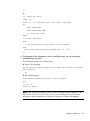
Wait at least two or three minutes before you attempt to run the tests.
or
Implement one of the following in shell or Perl:
diags start
sleep 240
rc = diags get state
if (rc ==0)
then
# run desired tests using diags run tests command
else
echo "Diagnostics not loaded in expected time. rc = $rc"
12
Sun Fire V20z and Sun Fire V40z Servers Troubleshooting Techniques and Diagnostics Guide • July 2005
fi
or
rc = diags get state
timer = 0
while (rc == 25 (device error)) and (timer < MAX_WAIT)
do
sleep SLEEP_TIME
timer=time+SLEEP_TIME
rc = diags get state
done
if (timer < MAX_WAIT)
then
# run desired tests using diags run tests command
else
echo "Error loading platform diagnostics. rc = $rc"
fi
4. To determine if the diagnostics tests are available to run, you can execute the
command diags get state.
The command returns one of these states:
■
Success Text message
The SP and the platform diagnostics systems are available to receive
test requests.
or
■
Error Text Message
The platform diagnostics system is not available.
end
if re == 0
diags run tests -a
Note – See “Running Diagnostic Tests,” below, for command-line arguments. See
the Sun Fire V20z and Sun Fire V40z Servers—Server Management Guide for more
information about commands and the use of scripts for systems management.
Chapter 2
Diagnostics
13
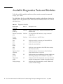
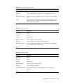
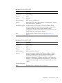
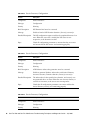
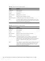
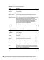
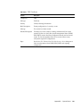
Available Diagnostics Tests and Modules
To list the available modules and the tests they contain, execute the command:
diags get tests.
The table below lists the available diagnostics modules and indicates whether the
module runs on the platform OS or on the SP. Each module contains one or more
individual tests.
TABLE 2-1
14
Diagnostics Modules
Module Name
(command)
Runs on
Description of Test
Memory
(memory)
Platform
Identify memory errors, address decoding faults, and
dataline faults
Network Controllers
(nic)
Platform
Test the platform NIC interfaces, using an internal
loopback test.
Storage
(storage)
Platform
Invoke self-tests on the SCSI drive.
Fans
(fan)
SP
Verify that each fan is rotating and that the RPM is
within the specified ranges.
Flash
(flash)
SP
Read and write flash files.
LED
(led)
SP
Verify the correct operation of the LED drive circuitry.
(Non-interactive tests.)
Operator Panel
(oppanel)
SP
Verify the memory of the Operator Panel. Indicates
values and locations of any errors.
Power
(power)
SP
Verify that the power backplane and power supplies are
functioning properly. (Not available for all systems.)
Temperature
(temp)
SP
Verify that each of the temperature sensors is functional
and that the temperature is within the specified ranges.
Voltage (voltage)
SP
Verify the derived (generated by various VRMs in the
system) and bulk voltages.
Sun Fire V20z and Sun Fire V40z Servers Troubleshooting Techniques and Diagnostics Guide • July 2005
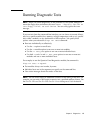
Running Diagnostic Tests
Note – When you launch diagnostics on the platform OS, the system attempts to
mount the floppy drive and returns this error: mount : Mounting /dev/fd0 on
/mnt/floppy failed. No such device. You can safely ignore this error
message.
If you run tests from the command-line interface, you can choose to execute all tests,
tests for a specific module (fans, memory, voltage, temperature, and so on), specific
tests within a module, or any combination of these options. You specify these
options when you execute the diags run tests command.
■
Run tests individually or collectively.
■
Use the -a option to run all tests.
■
Use the -m module option to run one or more test modules.
■
Use the -n test_name option to run one or more individual tests.
■
Use both -m module and -n test_name options to run one or more test
modules and one or more individual tests.
For example, to run the Operator Panel diagnostics module, the command is:
diags run tests –m oppanel.
■
Test modules always run in order, by name.
■
Individual tests run in the sequence you specify on the command line.
■
View status messages about the success of the tests.
Note – You can write scripts for additional control over the timing of the tests. For
example, you can write a shell script to repeat a test a specified number of times. See
the Sun Fire V20z and Sun Fire V40z Servers—Server Management Guide for details.
Chapter 2
Diagnostics
15
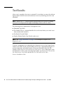
Test Results
After a test is complete, the status is returned. If a test detects an error, the software
reports details about the error and continues to run any remaining tests that were
submitted.
Note – Specify the -v| --verbose option to display details for all tests, including
successes. For example, details might include high, normal, and low values.
The following data is generated for all diagnostics tests.
■
Submitted Test Name
■
Test Handle (This is a unique identifier that can be used when you cancel a test
from another shell window.)
■
Test Result (Passed, Failed)
■
Details (Failure Details, Tests Details, and so on.)
Note – See “Diags Test Results” on page 51, for examples of output for all
diagnostics tests.
To locate a component that is identified by a diagnostics test see the System Status
window of the SM Console, which enables you to view a representative display of
system components and related sensors. For more information about the SM
Console, see the Sun Fire V20z and Sun Fire V40z Servers—Server Management Guide.
For illustrations of the system and component labels, see the Sun Fire V20z and Sun
Fire V40z Servers—User Guide and the Sun Fire V20z and Sun Fire V40z
Servers—Installation Guide.
16
Sun Fire V20z and Sun Fire V40z Servers Troubleshooting Techniques and Diagnostics Guide • July 2005
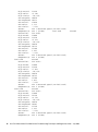
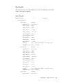
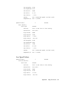
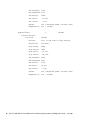
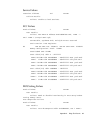
Sample Output
This section contains output that could be returned if you start diags in no-platform
mode, with the power on, and with the --verbose argument. For example:
diags start -n
platform set power state on -f
diags run tests -a -v
Typical output is included below:
Submitted Test Name
speed.allFans
Results
Submitted Test Name
speed.allFans
Test Details:
fan1.tach
Controller:
High Rated:
High Actual:
High Delta:
High Limits:
Low Setpoint:
Low Expected:
Low Actual:
Low Delta:
Low Limits:
Sensor:
Component(s):
fan2.tach
Controller:
High Rated:
High Actual:
High Delta:
High Limits:
Low Setpoint:
Low Expected:
Low Actual:
Low Delta:
Low Limits:
Sensor:
Component(s):
fan3.tach
Controller:
High Rated:
Test Handle
1
Test Handle
1
Test Result
Passed
Passed
fan-ctrl
13000
13740
+5.39%
-10/+35%
10010
10580
11100
4.69%
-/+15%
Fan 1 measured speed (ID=fan1.tach)
Fan 1 (ID=NA)
Passed
fan-ctrl
13000
13920
+6.61%
-10/+35%
10010
10718
11100
3.44%
-/+15%
Fan 2 measured speed (ID=fan2.tach)
Fan 2 (ID=NA)
Passed
fan-ctrl1
13000
Chapter 2
Diagnostics
17
High Actual:
High Delta:
High Limits:
Low Setpoint:
Low Expected:
Low Actual:
Low Delta:
Low Limits:
Sensor:
Component(s):
Controller:
High Rated:
High Actual:
High Delta:
High Limits:
Low Setpoint:
Low Expected:
Low Actual:
Low Delta:
Low Limits:
Sensor:
Component(s):
fan5.tach
Controller:
High Rated:
High Actual:
High Delta:
High Limits:
Low Setpoint:
Low Expected:
Low Actual:
Low Delta:
Low Limits:
Sensor:
Component(s):
fan6.tach
Controller:
High Rated:
High Actual:
High Delta:
High Limits:
Low Setpoint:
Low Expected:
Low Actual:
Low Delta:
Low Limits:
Sensor:
Component(s):
18
13860
+6.20%
-10/+35%
10010
10672
11040
3.33%
-/+15%
Fan 3 measured
Fan 3 (ID=NA)
fan-ctrl1
13000
13920
+6.61%
-10/+35%
10010
10718
11100
3.44%
-/+15%
Fan 4 measured
Fan 4 (ID=NA)
Passed
fan-ctrl2
13000
13980
+7.01%
-10/+35%
10010
10765
11100
3.02%
-/+15%
Fan 5 measured
Fan 5 (ID=NA)
Passed
fan-ctrl2
13000
14160
+8.19%
-10/+35%
10010
10903
11340
3.85%
-/+15%
Fan 6 measured
Fan 6 (ID=NA)
speed (ID=fan3.tach)
fan4.tach
Passed
speed (ID=fan4.tach)
speed (ID=fan5.tach)
speed (ID=fan6.tach)
Sun Fire V20z and Sun Fire V40z Servers Troubleshooting Techniques and Diagnostics Guide • July 2005
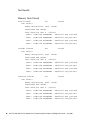
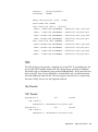
Saving Test Results
SP-based Diagnostics
To save SP-based diagnostic test results, save the output as a network share volume
file. For example, to save results of all the tests that you run in diags.log1, use:
diags run tests -all > /mnt/log/diags.log1
CD-Based Diagnostics Tests
To save CD-Based diagnostic test results, mount a USB stick or a floppy drive and
save the results.
■
To mount a USB stick use this command:
mount /usbstorage
Note – Mounting usbstorage works only if you have a single disk drive in your
system.
■
To mount a floppy, use this command:
mount /floppy
■
To remove the device, use this command:
umount /<usbstorage | floppy>
Stopping Tests
■
To cancel one or more individual tests, run this command:
diags cancel tests {-t|--test} TEST HANDLE {-a|--all}
■
To stop all tests, press Ctrl+C from within the shell in which you started the
tests.
■
To terminate all diagnostics tests and end the session, run the diags terminate
command.
Chapter 2
Diagnostics
19
20
Sun Fire V20z and Sun Fire V40z Servers Troubleshooting Techniques and Diagnostics Guide • July 2005
CHAPTER
3
Troubleshooting Topics
This chapter contains troubleshooting instructions and references for a variety of
issues. Information is organized alphabetically, according to general topics, is crossreferenced as necessary, and is indexed in the last section of this document.
BIOS
This section describes possible causes and suggested troubleshooting steps for
systems management events that are related to BIOS.
Note – See the Sun Fire V20z and Sun Fire V40z Servers—Server Management Guide
and the SM Console Online Help for information about how to update the BIOS. See
“Update Failed” on page 83, to troubleshoot BIOS updates.
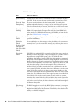
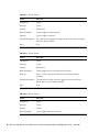
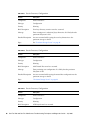
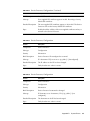
BIOS Error or Warning Events
The errors listed in the table below are returned by the sp get events command.
The possible causes and suggested actions to take in order to resolve each problem
(in order of probability, based on experience) are listed below.
Note – See the Sun Fire V20z and Sun Fire V40z Servers—Server Management Guide for
more information about the sp get events command.
21
TABLE 3-1
BIOS Error Messages
Error
Solution or Reference
[CPU ID Error]
Possible cause of this error is unmatched CPU Revs. Determine the Rev of
each CPU. If they are not the same, replace with consistent Rev CPUs.
[Date and Time
Setting Error]
This error usually indicates that the battery failed. To remedy this
problem replace the battery, run setup, set time and date, cycle power
with a five-minute delay in off state, and check to see if the error recurs.
[Diag Failed
Memtest]
To remedy this problem, replace the reported DIMM, then reboot.If other
DIMMs fail, replace them and repeat the test.If the same DIMM fails,
replace entire set of DIMMs with known good DIMMs, and run the tests
again. See “DIMM Faults” on page 26.
[Diagnostic Load During loading of the diagnostics from the SP to the platform, the load
Failure]
operation failed. Retry.
[DMA Test
Failed],
[Software NMI
Failed], [FailSafe Timer NMI
Failed]
You are unlikely to see this message as the probability of its occurrence is
extremely low. If you do receive this message, try rebooting the server.
[Fixed Disk
Failure]
If all HDDs in a multiple-HDD system have failed, the power supply is
the likely source of the problem. The power supply is a possible source of
the problem in a single-HDD system, also. But check the other
possibilities listed below, first.The HDD data cable might be connected
improperly or the backplane connector mating might be skewed. Ensure
that the connector is securely connected to the backplane. A drive might
not be inserted completely. Pull out the drive, inspect it, reinsert it, and
verify that the mating is smooth and complete. Drive electronics or
interface failed. If possible, insert the drive into a different slot in the
same system.If possible, insert the drive into a different slot in the same
system. If the drive works in the other system, return the drive to the
server that experienced the initial problem.If the drive fails in the other
system also, try a different drive in the original system, if possible.If the
second drive works in the second system, but not in the first system,
return the first system.If the drive that worked in the second system does
not work in the first system and the drive from the first system does not
work in the second system, the drive electronics and backplane might be
bad. Return the system.
[Flash Image
The BIOS Image that is used in the BIOS Update command is corrupted,
Validation Error] or was not a BIOS image (wrong filename), or the transfer of the image to
the platform failed. Retry the operation. If it still fails, check that the file is
actually a valid BIOS image file.
22
Sun Fire V20z and Sun Fire V40z Servers Troubleshooting Techniques and Diagnostics Guide • July 2005
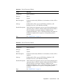
TABLE 3-1
BIOS Error Messages (Continued)
Error
Solution or Reference
[Flash Process
Failure]
This error probably indicates that the flash chip is defective. To remedy
the problem, replace the flash chip. If the problem persists, it might
indicate a problem that is not serviceable by the user. Contact the Support
Center.
[Incorrect BIOS
image file]
The BIOS Image provided to the BIOS update command is a BIOS for a
different platform. Obtain the correct BIOS image for your platform.
[IP Failure]
An internal communication error occurred between BIOS and the SP.
Retry the operation.
[Memory
Mismatched]
Pairs of DIMMs must match. Determine if DIMMs in each pair match,
and reconfigure, if necessary. See “DIMM Faults” on page 26.
[Operating
System not
found]
Possible causes of this error are: Empty drive or media (contains no boot
block).Intended boot device is not in the BIOS setup boot settings.Floppy
disk was left in floppy drive.Media is damaged or corrupted. (Usually
this is caught under fixed drive failure, if booting from the hard drive.)
[Parity Error
(Memory)],
[Extended
Memory
Truncation]
BIOS probably would report a bad DIMM mapped out. If either of these
errors occurs intermittently, run memory tests. See “Diagnostics” on
page 7, and “Memory” on page 59.
[Real-Time
Clock Error]
This error can indicate a South bridge failure, a BIOS failure, a bad
crystal, or a bad oscillator. Possible solutions are to re-flash the BIOS or to
replace the battery.
[Shadow RAM
Failed], [System
RAM Failed],
[Extended RAM
Failed]
These errors indicate a general memory DIMM error. The first two
indicate that the failure occurred below the first MG of RAM. See “DIMM
Faults” on page 26, for details.If you are unable to boot the diagnostics
kernel, replace all DIMMs with known good DIMMs. If this is successful,
then use diagnostics to identify the bad DIMMs.
[System Timer
Error]
This is a legacy error. It can indicate a South bridge failure or a BIOS
failure. The most likely cause is a corrupted BIOS. To remedy this, re-flash
the BIOS.
Received [early] BIOS can detect some hardware errors before enough of the system is
fatal error from working to report a more specific error code. If known good CPUs are
BIOS: [Unable to installed, contact the Support Center for help.
do anything]
Chapter 3
Troubleshooting Topics
23
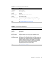
TABLE 3-2
BIOS Warning Messages
Warning
Solution or Reference
[CMOS
Checksum
Failure],
[CMOS
Settings do not
match
hardware
configuration],
[CMOS
Invalid]
To remedy these problems re-run setup (see “BIOS Configuration”
in the Software Installation and Configuration Guide), save, exit,
and cycle power. If one of the errors occurs again, replace the
battery, run setup, set time and date cycle power with a fiveminute delay in off state.If the problem recurs, contact the
Support Center.
[PCI-X Slot
During setup (see “BIOS Configuration” in the Software
disabled for
Installation and Configuration Guide), ensure that in the
8131 Errata 56] Advanced menu, you set the option to allow the card to be
recognized. Do this only if you are certain that the card will not
cause data corruption, or are willing to take the risk. The card was
powered off to prevent data corruption. For more information, see
the Sun Fire V20z and Sun Fire V40z Servers—Release Notes.
Received
warning from
BIOS: [CMOS
Battery
Failure]
This error probably indicates a battery failure. To remedy this
problem replace the battery, run setup, set time and date, cycle
power with a five-minute delay in off state.If the problem recurs,
contact the Support Center.
BIOS POST Codes
If hardware or configuration errors occur, the BIOS displays warning or error
messages on the video display, if one is attached. However, some errors can be so
severe that the BIOS cannot initialize the video or halts immediately. In these cases,
you can determine the last Power On Self Test (POST) task that the BIOS executed. It
is indicated by the value written to port 80.
24
■
The sp get port80 command - For information about how to use this
command to retrieve the last port 80 post code, see the SM Console Online Help
or the Sun Fire V20z and Sun Fire V40z Servers—Server Management Guide.
■
Last 10 POST codes - For information about how to use the Operator Panel to
retrieve the last 10 port 80 POST codes, see the Sun Fire V20z and Sun Fire V40z
Servers—Server Management Guide.
■
POST codes and definitions - “POST Codes” on page 103, provides a list of POST
codes and brief definitions.
Sun Fire V20z and Sun Fire V40z Servers Troubleshooting Techniques and Diagnostics Guide • July 2005
■
BIOS Error or Warning Events - The section above includes information about the
problems that produce the most frequently reported POST codes, with tips for
problem resolution.
The most common POST codes that are reported on the Sun Fire V20z and Sun Fire
V40z servers and suggested troubleshooting actions are listed in the table, below.
TABLE 3-3
Common POST Codes
POST Code
Reference or Solution
00
Indicates that no BIOS executed far enough to write any POST codes. This
usually is caused by failure to power on, fatal CPU, or a fatal BIOS flash
part issue.
C0
Indicates that an operating system was not detected.
28
Indicates that the SPDs on a DIMM did not read correctly. Probably
indicates a bad DIMM. See “DIMM Faults” on page 26.
2C
An address or a data error caused by a bad DIMM, VRM, or CPU. See
“DIMM Faults” on page 26.
49
PCI config space error. Remove PCI boards to find offending board,
shuffle order, replace, or use other brand as needed.
Boot Issues
For information about boot problems that are associated with the platform OS, see
“Platform OS Does not Boot” on page 36. For boot problems that are associated with
the SP, see “Service Processor” on page 41.
Clear CMOS Jumper
In some troubleshooting procedures, it is necessary to clear the CMOS jumper.
Instructions for this procedure are below.
■
In the Sun Fire V20z Server, the CMOS jumper is J110.
■
In the Sun Fire V40z Server, the CMOS jumper is J125.
1. Power down the server.
2. Disconnect the AC power cord. If you have two power supplies, disconnect both
AC power cords.
Chapter 3
Troubleshooting Topics
25
3. Remove the system cover as instructed in the Hardware Components and Service
document.
4. Locate the appropriate jumper. Facing the server from the front panel:
■
In the Sun Fire V20z Server, J110 is located on the left rear area of the
motherboard.
■
In the Sun Fire V40z Server, J125 is located right of the middle area of the
motherboard.
5. Move the jumper to the parked position (away from the dot) so that the CMOS
clears on the next boot.
6. Replace the system cover and reconnect the AC power.
7. Reboot the server and press F2 during the boot, to go into the BIOS setup.
8. Press F9 to set defaults.
9. Press F10 to save changes.
10. Power down the server, disconnect the AC power cord(s), and remove the system
cover.
11. Move the jumper back to the active position (closer to the dot) so that the CMOS
retains setting on the next boot.
12. Replace the system cover, reconnect the AC power, and reboot the server.
DIMM Faults
Note – To enable DIMM fault reporting, you must install the NSV software on your
system, as detailed in the Sun Fire V20z and Sun Fire V40z Servers—Installation Guide.
Although these drivers are available in the NSV, it is not necessary to mount the
NSV to the SP in order to enable this functionality.
The system fault LED blinks and identifies uncorrectable DIMM faults or correctable
faults that exceed the threshold. Faults also are reported in the event log, the SM
Console, and diags memory tests. (See “ECC Errors” on page 27, for an example of
diags output that reports a DIMM fault.) The system might continue to operate
normally, depending on the type of failure, the location of the failure, and the
robustness of the platform operating system.
26
Sun Fire V20z and Sun Fire V40z Servers Troubleshooting Techniques and Diagnostics Guide • July 2005
IPMI System Event Log (SEL) records are generated for both correctable and
uncorrectable DIMM ECC errors. To determine the type of error, examine the sensorspecific offset in Event Data 1. The CPU (memory bank) and DIMM numbers are
located in the high and low nibbles of the Event Data 3 field, respectively.
■
If the error is uncorrectable, shut down the system and replace the DIMM.
■
If the error is correctable, clear the initial, correctable DIMM errors, then monitor
the system to determine if the problem recurs. You can continue to clear the
correctable errors and monitor the system, but be aware that repetitive correctable
errors might eventually cause uncorrectable errors.
Note – See the Operator Panel’s server menu options in the Sun Fire V20z and Sun
Fire V40z Servers—Server Management Guide. These errors also appear in the system
events log. See “System Events” on page 79.
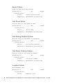
ECC Errors
In both the Sun Fire V20z Server and the Sun Fire V40z Server, each CPU can
support four DIMMs.
■
For each CPU, the four DIMM slots are grouped into two banks (bank 0 and bank
1), each with two DIMM slots.
■
You must install the DIMMs in matched pairs, one bank at a time. The two
DIMMs in a given bank must be of the same size, type and vendor.
■
Each CPU can support two banks of DIMMs. Although each bank must contain a
pair of matching DIMMs, it is not necessary that the size and vendor of the
DIMMs between bank 0 and bank 1 match.
If your log files report an ECC error or a problem with a memory DIMM, complete
the steps below.
Note – See “Log Files” on page 30, for a summary of log files that are available with
your server.
In the example below, the log file reports an error with the DIMM in CPU0, bank 0,
slot 1.
1. Power down your server and remove the cover.
2. Remove the DIMMs that were indicated in the log file and label them.
Chapter 3
Troubleshooting Topics
27
3. Visually inspect the DIMMs for physical damage, dust, or any other
contamination on the connector.
4. Visually inspect the DIMM slots for physical damage. Look for cracked or broken
plastic on the slot.
5. Dust off the DIMMs, clean the contacts, and reseat them. (You can leave the labels
on the DIMMs.)
6. Reboot the system. If the problem persists, continue to Step 7.
7. Power down the server again and remove the cover.
8. Remove the DIMMs that were identified in the log file.
9. Exchange the individual DIMMs between the two slots of a given bank. Ensure
that they are inserted correctly, with latches secured.
■
This step can isolate the problem to one of the DIMMs, or confirm that it is due to
some other cause, such as a bad slot on the motherboard.
■
In this example, remove both DIMMs from bank 0 for CPU0 and switch the
DIMMs between the slots.
10. Power on the server and run the process that caused the DIMM error.
11. Review the log file. (See “ECC Failure” on page 96, for sample output.)
12. If the error now appears in CPU0, bank 0, slot 0 (opposite to the original error),
the problem is related to the individual DIMM that is now in slot 0.
or
If the error still appears in CPU0, bank 0, slot 1 (as the original error did), the
problem is not related to an individual DIMM. Instead, it might be caused by
CPU0 or by the DDR VRM for CPU0.
13. If you have a Sun Fire V20z Server with a single CPU, you cannot independently
troubleshoot the problem any further. A replacement part might be necessary.
or
If you have a server with at least two CPUs, continue with Step 14.
14. Label, then exchange the memory VRMs between the two CPUs.
■
This step can isolate the problem to the memory VRM for CPU0 or confirm that it
is due to some other cause.
■
In this example, remove the VRMs for CPU0 and CPU1, then switch the DDR
VRMs between the CPUs.
15. Power on the server and run the process that caused the DIMM error.
16. Review the log file.
28
Sun Fire V20z and Sun Fire V40z Servers Troubleshooting Techniques and Diagnostics Guide • July 2005
17. If the error now appears on CPU1 (a different CPU from the original error), the
problem is related to the DDR VRM that originally was seated for CPU0. A
replacement part might be necessary.
or
If the error still appears in CPU0, bank 0, slot 1 (as the original error did), the
problem is not related to the memory VRM. It might be due to CPU0 or the
motherboard. A replacement part might be necessary.
Inventory
Use the inventory get all, inventory get hardware, and inventory get
software commands to view a list of field-replaceable hardware components or
current software components and versions. See the Sun Fire V20z and Sun Fire V40z
Servers—Server Management Guide for details about these commands.
If you have an NSV version 2.2 or earlier, and you add a newer NSV version to the
same location, the inventory get software command, with the [{-a|--all}]
argument, might time out. If this is the case, follow the instructions, below.
1. Move and unzip any newer NSV versions to a different location from the location
of your 2.2 NSV.
or
Review the older NSV and remove folders for operating systems that you no
longer need.
2. Try the command again.
Chapter 3
Troubleshooting Topics
29
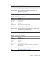
Lights, LCD, LED
TABLE 3-4
Lights on the Front Panel
Problem
Solution or Reference
Locate light
blinks
The Locate Light can be illuminated (or extinguished) by pressing the
Locate Light button beside it. The system administrator turns the Locate
Light on in order to simplify the task of locating a specific server. A
blinking Locate Light does not indicate a problem.
System Fault
LED is
illuminated
The System Fault LED (Machine Check Error) light is illuminated when a
variance occurs. For troubleshooting tips, see “Machine Check Error” on
page 31, “System Events” on page 47, and “System Events” on page 79 for
more information.
Platform Power
State Indicator
light is not
illuminated
Check power connection to AC. On the Sun Fire V20z Server, check the
AC Power Switch and the AC Present Indicator on the back panel.
Operator Panel
LCD is not
illuminated
Check power connection to AC. On the Sun Fire V20z Server, check the
AC Power Switch and the AC Present Indicator on the back panel. See
also various SP boot issues and solutions in “Service Processor” on
page 41.
LCD displays
“SP booting,”
then hangs
Use the SP Reset button to reboot the SP. (The SP Reset button is on the
back panel.)
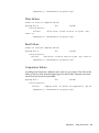
Log Files
Depending on the functions and features you use, your server can produce these log
files:
30
■
IPMI event log - See the Systems Management Guide for more information about
IPMI functionality. When the IPMI log is full, it rejects new entries.
■
SP Event Log - See “System Events” on page 79, and “Service Processor,
ResourceAllocation” on page 96 for more information.
■
Diagnostics log files - See “Diags Test Results” on page 51 for more information.
■
TDU log files - See “Troubleshooting Dump Utility” on page 4 and see the
Systems Management Guide for more information.
Sun Fire V20z and Sun Fire V40z Servers Troubleshooting Techniques and Diagnostics Guide • July 2005
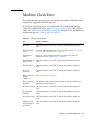
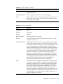
Machine Check Error
This section describes possible causes of events that are related to Machine Checks,
and provides suggested troubleshooting steps.
If a Machine Check error occurs, the System Fault LED is illuminated. Machine
Check errors indicate EEC errors (see “ECC Errors” on page 27) or VRM Crowbar
events (see “VRM Crowbar Assertions” on page 49). These errors are reported in the
system event log (see “System Events” on page 79).
TABLE 3-5
Machine Check Errors
Error
Solution or Reference
[Bus Unit]
This error indicates a bad CPU. To remedy the problem, replace the
CPU.
[Correctable ECC
error.]
This error indicates memory ECC errors, with ECC on. See “ECC Errors”
on page 27. See “DIMM Faults” on page 26.
[Detected on a
scrub.]
Raw data: <data>. This error should occur with a CPU error or a
memory error. See “DIMM Faults” on page 26.
Error detected in
[Data Cache]
This error indicates a bad CPU. To remedy the problem, replace the
CPU.
[Error IP Valid.]
This error indicates a bad CPU. To remedy the problem, replace the
CPU.
[Error not
corrected]
This error indicates a bad CPU. To remedy the problem, replace the
CPU.
[Error occurred at
address
<address>.]
See “DIMM Faults” on page 26.
[Error reporting
disabled.]
The machine check feature has been turned off. For maximum system
reliability, leave this option on.
[InstructionCache] This error indicates a bad CPU. To remedy the problem, replace the
CPU.
[Invalid bank
reached]
This error indicates a bad CPU. To remedy the problem, replace the
CPU.
[Load/Store unit]
This error indicates a bad CPU. To remedy the problem, replace the
CPU.
Machine Check
error detected on
cpu <CPU>
This error indicates a bad CPU. To remedy the problem, replace the
CPU.
Chapter 3
Troubleshooting Topics
31
TABLE 3-5
Machine Check Errors (Continued)
Error
Solution or Reference
[Machine Check in This error indicates a bad CPU. To remedy the problem, replace the
Progress.]
CPU.
[Misc. register
contains more
info.]
This error indicates a bad CPU. To remedy the problem, replace the
CPU.
[North Bridge]
This error indicates a bad CPU. To remedy the problem, replace the
CPU.
[Processor state
may have been
corrupted]
Any specific details that are included with this error message, such as
addresses, might be inaccurate, and are unreliable for further
troubleshooting.
[Restart IP Valid.]
This error indicates a bad CPU. To remedy the problem, replace the
CPU.
[Second error
detected.]
This error indicates a bad CPU. To remedy the problem, replace the
CPU.
[Un-correctable
ECC error.]
This error indicates memory ECC errors. See “ECC Errors” on page 27.
See “DIMM Faults” on page 26.
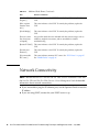
Network Connectivity
Note – Review the Sun Fire V20z and Sun Fire V40z Servers—Installation Guide and
the Sun Fire V20z and Sun Fire V40z Servers—Server Management Guide for detailed
information about network connectivity.
32
■
If you are unable to ping the SP ethernet port, use the Operator Panel to reset the
IP address.
■
If you are using DHCP, ensure that your DHCP server is up.
Sun Fire V20z and Sun Fire V40z Servers Troubleshooting Techniques and Diagnostics Guide • July 2005
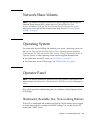
Network Share Volume
Note – For detailed information about how to install, upgrade, and manage the
Network Share Volume (NSV), see the Sun Fire V20z and Sun Fire V40z
Servers—Installation Guide, the Sun Fire V20z and Sun Fire V40z Servers—Server
Management Guide and the SM Console Online Help. See also “Restore Default
Settings” on page 38.
Operating System
For information about installing and updating your server’s operating system, see
the Sun Fire V20z and Sun Fire V40z Servers—Linux Operating System Installation
Guide, the Sun Fire V20z and Sun Fire V40z Servers—Guide for Pre-installed Solaris 10
Operating System, or other operating system vendor-supplied documentation.
■
For information about ECC errors, see “ECC Errors” on page 27.
■
For information about OS boot hangs, see “DIMM Faults” on page 26.
Operator Panel
Note – For detailed information about the use of the Operator Panel buttons and
other controls, see the Sun Fire V20z and Sun Fire V40z Servers—Server Management
Guide.
This section provides troubleshooting ideas for problems with the Operator Panel
LCD display.
Illuminated, Readable Text, Non-working Buttons
If the LCD is illuminated and readable text displays, but the buttons do not appear
to work, there could be a problem with DHCP settings. It is possible that the SP
cannot find a DHCP server.
Chapter 3
Troubleshooting Topics
33
1. Use the SM Console or SM commands to ensure that the SP network is set to
DHCP.
2. Reboot the SP.
Note – For solutions to SP problems that cause this symptom, see the SP boot issues
in “Service Processor” on page 41.
Illuminated, Unreadable Text
If the LCD is illuminated, but the text is unreadable, check and reseat the cables. If
the problem persists, it might indicate that the motherboard is faulty. Replace the
motherboard.
Illuminated, No Text
If the LCD is illuminated, but no text displays, one of the following might be the
cause.
■
If you performed a PIC Update, this symptom indicates that the boot mode
probably has been altered and must be reset to defaults before the SP can boot. To
accomplish this, see “Failure to Boot” on page 43, and “Failure to Boot after
Downgrade” on page 45.
■
If you updated PPCBoot, this symptom indicates that the update damaged the
system. The system must be replaced.
■
If you attempted to update PRS, this symptom indicates that the process did not
complete, and that the system was damaged. The system must be replaced.
■
If you did not perform any updates, the problem might be with the Operator
Panel assembly. Replace the Operator Panel Assembly.
No Illumination
As noted in “Lights, LCD, LED” on page 30, if the panel is not illuminated, check the
cable connections. If all cables are securely seated, other possible causes of this
symptom include problems with the LCD, with the Operator Panel assembly, or with
the motherboard.
34
Sun Fire V20z and Sun Fire V40z Servers Troubleshooting Techniques and Diagnostics Guide • July 2005
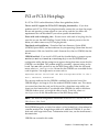
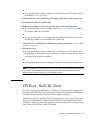
PCI or PCI-X Hot-plugs
If a PCI or PCI-X card malfunctions, follow these guidelines, below.
Drivers and OS support for PCI or PCI-X hot-plug functionality - If you have
problems with PCI or PCI-X hot-plug functionality, ensure that you have the proper
drivers and operating system support on your server, and that you follow the
requirements that are described in your server-specific documentation.
Errors with cards in hot-plug slots - If errors occur with cards in hot-plug slots, be
sure that you use the AMD HotPlug Control Utility to remove power to the slot
before you add or remove any PCI hot-plug devices.
Downloads and installations - Download the latest firmware, Option ROM
(OPROM, Option BIOS), and device drivers for your operating system from the card
manufacturer’s Web site. Install the card’s firmware first, then its OPROM, then the
drivers.
OPROM enabled - If you install a SCSI card that should display a prompt to press
Ctrl-A (or Ctrl-C, or Ctrl-S, or Ctrl-any key) to run the OPROM-based
configuration utility, but the prompt never appears during boot time, ensure that the
OPROM is not disabled. This problem might be caused by a jumper setting on the
board. Press F2 while you boot to run the BIOS Setup utility. From the Advanced
menu, select PCI Configuration. Ensure that the OPROM scan is enabled for the
card in question. You might receive an error such as:
Expansion ROM not initialized -PCI Mass Storage Controller in slot 3
Bus:3, Device:02, Function:01
This message indicates that the OPROM is enabled, but the initial size of the
OPROM image is too large to fit in the standard OPROM shadow area. This means
you cannot boot from the card, and if the card has a boot-time setup utility, you
cannot use that functionality. If you disable other OPROMs (in order to free more
OPROM shadow space), you might be able to load it. To do this, select PCI
Configuration on the Advanced menu of the BIOS Setup utility.
Note – See the BIOS configuration information in the Sun Fire V20z and Sun Fire
V40z Servers—User Guide.
Each OPROM image has an initial size when it is first loaded, but is later reduced to
a smaller residual size. It might be possible to fit additional OPROMs, if you first
load cards with larger initial sizes. To determine initial sizes, see the manufacturer’s
documentation.
OPROMs are scanned in this order:
Chapter 3
Troubleshooting Topics
35
1. On-board devices (Video, NICs, SCSI)
2. Physical Slot 1
3. Physical Slot 2
4. Physical Slot 3
5. Physical Slot 6
6. Physical Slot 7
7. Physical Slot 4
8. Physical Slot 5
Note – You can change the boot order from the Boot menu of the BIOS Setup utility,
but you cannot change the order of OPROM scans.
Platform OS Does not Boot
This issue can result from poor cable connections or poorly seated hardware. If your
platform OS does not boot, follow the steps below.
1. Verify that AC power is available and that the AC power cord is connected
securely to the AC connector on the server’s power supply. If you have a server
with two power supplies, ensure that both are connected securely. If you have a
2100 server, ensure that the AC switch on the back of the server is in the “on”
position.
2. If you have power to the SP but not the platform, power down your server, unplug
the AC connector from the wall, and remove the system cover. See the Hardware
Components and Service document for instructions about how to remove the
system cover.
a. Ensure that the SCSI signal cable, SCSI power cable, and other internal cables
are attached securely.
b. Ensure that all DIMMs, DDR VRMs, and CPU VRMs are seated firmly in their
respective slots.
c. Remove all PCI option cards from the server.
3. Replace the system cover, reconnect the AC power, and reboot the server.
■
36
If the platform does not boot, go to Step 7.
Sun Fire V20z and Sun Fire V40z Servers Troubleshooting Techniques and Diagnostics Guide • July 2005
or
■
If the platform boots without incident and you removed any PCI option cards as
instructed in Step 2, go to Step 4.
4. Power down the server, disconnect the AC power, and remove the system cover.
5. Re-install one of the PCI option cards.
6. Replace the system cover, reconnect the AC power, and reboot the server.
■
If the platform boots without incident, repeat Step 4, Step 5, and Step 6, until all
PCI options cards are re-installed.
or
■
If, after you re-install any PCI option card, the platform does not boot, you have
isolated the problem to an individual PCI option card.
7. Clear the server’s CMOS jumper. Follow the procedure outlined in “Clear CMOS
Jumper” on page 25.
8. Reboot the server.
■
If the platform boots without incident and you removed any PCI option cards,
replace them, as instructed in Step 5 and Step 6, in order to isolate the option card
that might have caused the problem.
or
■
If the platform does not boot, it might be necessary to replace the motherboard.
Note – In versions 2.3 and later, you can set an IPMI boot option parameter to clear
the CMOS. This eliminates the need to remove the system cover and move the
jumper from the active position to the parked position.
PPCBoot - Bad CRC Error
This error message does not indicate a critical error. The situation that triggers this
message occurs only when you connect via the Serial Port, perform a flash update,
and disconnect or reset the SP before PPCBoot update completes.
Immediately after the “Bad CRC Error” message displays, the system retrieves the
necessary environmental variables and writes them into the appropriate partition.
On the next reboot, the error message does not display, unless you once again reset
the SP before the PPCBoot update is complete.
Chapter 3
Troubleshooting Topics
37
Restore Default Settings
Note – Related material is included in “Failure to Retain User Accounts and
Settings” on page 45.
If you experience general problems with the SP (or simply wish to restore its original
settings), you can use the sp reset to default-settings command to restore
selected settings.
Note – You also can use the LCD buttons on the Operator Panel to restore default
settings. See the Sun Fire V20z and Sun Fire V40z Servers—Server Management Guide
for details.
The SP configuration files are stored in a persistent file system in the /pstore
directory. When the SP boots, it checks these files for existing configuration
information. By default, the SP will reboot 60 seconds after the sp reset to
default-settings command executes, unless you specify the --nowait option,
in which case the reboot occurs immediately. A message displays every 20 seconds
to indicate that the reboot will occur.
sp reset to default-settings {-a|--all}
[{-c|--config}] [{-n|--network}] [{-s|--ssh}]
[{-u|--users}] [{-W|--nowait}]
For example:
sp reset to default-settings {-a|--all}
The --all option resets all SP settings to their default configurations, including
events and IPMI settings (files are deleted immediately).
Note – To reset IPMI settings only, do not use the SP command. Instead, use the
IPMI command: ipmi reset. See the Sun Fire V20z and Sun Fire V40z
Servers—Server Management Guide for more information about IPMI and about all
commands.
38
Sun Fire V20z and Sun Fire V40z Servers Troubleshooting Techniques and Diagnostics Guide • July 2005
SCSI Configuration Utility
Note – For detailed information about how to use the SCSI Configuration Utility
that is included with your server, see the Sun Fire V20z and Sun Fire V40z
Servers—User Guide.
RAID Properties Menu Item Disabled
To resolve this problem, check these points:
■
Is the adapter in the boot adapter list?
■
Does the LSI adapter have Integrated Mirroring firmware?
■
Is an IM volume already created on each Fusion-MPT adapter in the system?
■
Is “Disable Integrated RAID” set to Yes in the Global Properties screen?
■
Are there at least two disks on the selected SCSI bus?
IM Volume Uses Extra SCSI ID
In this situation, the IM volume with two mirrored disks uses an extra SCSI ID off
the bus—none of the physical disks of the IM volume has the same SCSI ID as the
IM volume—and the configuration utility will not allow the disk at the ID that is
currently defined as the volume ID to be configured.
To change the IM volume configuration so that it does not use an extra SCSI ID, but
also keeps the same volume ID:
1. Go to the RAID Properties screen. Determine which SCSI ID the primary disk is
using and which SCSI ID the volume is using. Also determine the SCSI IDs of the
remaining disks of the IM volume.
2. Set the IM volume disks to “No” and save the configuration—break the volume.
3. Return to the RAID Properties screen and reconfigure the IM volume in this
manner:
■
Primary disk at same ID as before.
■
Secondary disk at ID used previously by the volume.
■
Hot spare at SCSI ID used previously by the secondary disk.
Chapter 3
Troubleshooting Topics
39
4. To save the configuration, press Esc and follow the on-screen instructions. This
creates the IM volume and triggers an automatic resync.
Configuration Utility Disables Selection of Disk
In this situation, the configuration utility does not allow a disk to be selected for an
IM volume.
To determine why the disk cannot be selected, press F4 on the RAID Properties
screen. The diagnostic codes for each disk display in the Size column. Code
definitions are in the table below.
TABLE 3-6
40
Diagnostic Codes for Disks
Code
Definition
0
Status is good.
1
Could not get serial number from disk.
2
Cannot confirm that disk has SMART capability.
3
Maximum disks have been configured for volume already.
4
Inquiry data that was returned says disk does not support wide, qtags,
disconnects, or sector size is not 512 bytes.
5
User disabled qtags or disconnects for disk on device properties screen.
6
Partitions on disk exceed size that can be mirrored by an already selected
secondary or hot spare disk.
7
Disk is not large enough to mirror partitions that are contained on
selected primary disk.
8
Hot spare was detected while no IM volume exists. You must delete hot
spare and save that configuration.
9
Disk partition uses some of all of the last 32 sectors of the disk (16
Kbytes). The last 32 sectors are required for IR (Integrated RAID) internal
processing.
10
Disk has sector size other than 512 bytes.
11
Device is not a compatible device type; must be a non-removable disk.
12
Hot spare is too small to mirror volume.
13
Maximum disks already are configured for volume.
Sun Fire V20z and Sun Fire V40z Servers Troubleshooting Techniques and Diagnostics Guide • July 2005
Service Processor
This section contains information about problems that are associated with the SP.
Note – For detailed information about how to set up, update, and use the SP, see the
Sun Fire V20z and Sun Fire V40z Servers—Installation Guide and the Sun Fire V20z and
Sun Fire V40z Servers—Server Management Guide.
‘Booting SP . . . ’ Displays on Operator Panel
If the SP image becomes corrupted, the SP fails to boot and the Operator Panel LCD
continuously displays the message: ‘Booting SP.’ If left for a number of minutes,
the fault light starts to blink and the SP reset button and the front buttons become
inoperable. As a result of this issue, you will be unable to access or configure the SP
via the Operator Panel, and the SP cannot monitor or manage the system.
A recovery operation is required. This operation is performed through the Operator
Panel after an AC power reset.
1. Setup the Java Update Server according to the procedures in the Server Management
Guide. Record the IP address of the server and the port number.
2. Disconnect the system from AC power.
3. Reconnect the system to AC power. The SP will start to boot and the following
will be displayed on the front panel:
SP Boot: <3..2..1> secAny Key for menu
4. Within three (3) seconds, press the Select (center) button on the Operator Panel to
interrupt the SP boot process. After you do this, the Operator Panel LCD displays
the following:
Menu:
Update SP?
5. Press the Select button to select the update operation. The following displays in
the Operator Panel’s LCD:
SP’s IP addr:
0.0.0.0
Chapter 3
Troubleshooting Topics
41
6. Use the buttons on the Operator Panel to specify and enter the SP’s IP address,
Netmask, and Gateway address, according to the procedures outlined in the
Systems Management Guide. After you specify the SP’s network information, the
following is displayed:
Update from IP:
0.0.0.0
7. Specify the IP address and port number of the Java Update Server you set up in
Step 1, using the front panel buttons as described above.
8. Confirm the update with the Select (center) button.
The SP update proceeds. You will be able to monitor the update process on the
Update Server, as well as on the Operator Panel.
Note – If you do not see output from the Update Server or if the Operator Panel
returns to the ‘Booting SP’ state, the SP could not reach the Update Server. Check
your network connections and settings and try again.
When the update is complete, the SP should be fully operational.
Continuous Boot of SP
A failure to initialize is usually caused by networking problems that are related to
either DHCP addressing or to the NSV server.
■
If configured for DHCP and the DHCP server is non-responsive or very slow to
respond, the SP can take too long to initialize and be reset by the PRS chip. If this
is the case, either repair the problem with the DHCP server or switch to static
addressing.
■
A non-responsive or slow-to-respond NSV server can also cause initialization to
fail. In this case, repair the problem with the NSV server, or use the sp delete
mount command to remove the NSV mount from the SP.
Networking issues or general connectivity issues (if external access is enabled)
usually cause loss of heartbeat. It can also be caused by intermittent problems on the
SP, such as sensor lockup or application failure.
42
■
Verify that the SP network settings are still valid (for example, DHCP/Static IP
addresses) and, if used, that the NSV mount point is valid and available.
■
Reboot the SP and see if the problem persists.
■
If it does, an AC power cycle of the system might be necessary to correct the
problem.
Sun Fire V20z and Sun Fire V40z Servers Troubleshooting Techniques and Diagnostics Guide • July 2005
■
If possible, attempt to reload the SP software with the sp update flash all
command from a known good image.
Note – For SP boot hangs, press the SP Reset button on the server’s back panel. Also
see “‘Booting SP . . . ’ Displays on Operator Panel” on page 41.
Failure to Boot
The boot mode probably has been altered. Reset the boot defaults. To accomplish
this, first either:
■
Log on to the SP with a Manager or Service account.
or
■
Attach a PC to the Serial Port.
Via the SP
1. Power down the server, disconnect the AC power cord(s), and remove the system
cover.
2. Place a jumper on TH84 pin set, which is located at the end of the 66 MHz PCI-X
slot. (Use the CMOS jumper for this purpose—from J110 or J125—if necessary.)
3. Establish an SSH session to the SP. Create an initial manager account as required,
according to the procedures in the Sun Fire V20z and Sun Fire V40z
Servers—Installation Guide.
Chapter 3
Troubleshooting Topics
43
4. To create a service-level account, enter:
access add user -g service -u s -p s3.
5. To su (super user) to the service account, enter:
su s
6. To enable the root account, enter:
sp set root on
7. Specify the service account password and new root account password, in response
to the prompt. At the $ type prompt, to su to the root account, enter:
su -
8. Specify the root account password you set in Step 5, in response to the next
prompt. At the # type prompt, enter:
setenv uboot 0
9. Power down the server, disconnect the AC power, and remove the system cover.
10. Remove jumper TH84.
11. Replace the system cover, reconnect the AC power, and power on the server.
The SP boot should succeed and the LCD should display appropriate text.
Via a PC Attached to the Serial Port
1. Power down the server, disconnect the AC power cord(s), and remove the system
cover.
2. Place a jumper on TH84 pin set, which is located at the end of the 66 MHz PCI-X
slot. (Use the CMOS jumper for this purpose—from J110 or J125—if necessary.)
3. Move the jumper at J19 to set the SP output to the Serial Port.
4. Attach a PC to the Serial Port.
5. Replace the system cover and reconnect the AC power cord(s).
6. Power on the server. The Serial Power displays:
Hit any Key to Stop Autoboot = 0.
7. Immediately press the space bar (within the first three seconds of the boot).
8. At the prompt => type:
saveenv
44
Sun Fire V20z and Sun Fire V40z Servers Troubleshooting Techniques and Diagnostics Guide • July 2005
9. Power down the server, disconnect the AC power cord(s), and remove the system
cover.
10. Remove the jumper you placed on pin set TH84.
11. Replace the system cover, reconnect the AC power cord(s), and power on the
server.
The SP boot should succeed and the LCD should display appropriate text.
Failure to Boot after Downgrade
If this problem occurs immediately after the SP starts booting, use the Operator
Panel to update the flash. Details are in the Sun Fire V20z and Sun Fire V40z
Servers—Installation Guide and the Sun Fire V20z and Sun Fire V40z Servers—User
Guide.
Note – The sp update flash all command does not update pstore data.
Details about the sp update flash all command are in the Sun Fire V20z and
Sun Fire V40z Servers—Server Management Guide.
Failure to Retain User Accounts and Settings
A corruption of the flash partition that is used to retain SP state information might
cause the failure to retain user accounts and settings across an SP reboot or AC
power reset. As a result of this issue you must reset desired settings after every SP
reboot. This can occur even though the SP is operational and accessible.
To identify this issue, log on to the SP and enter the mount command. An entry for
/pstore will not be present.
localhost $ mount
/dev/rd/0 on / type ext2 (rw)
none on /dev type devfs (rw)
proc on /proc type proc (rw)
localhost $
If you experience this problem, perform the following recovery operation through an
SSH session.
1. Establish an SSH session to the SP. Create an initial manager account as required,
according to the procedures in the Server Management Guide.
Chapter 3
Troubleshooting Topics
45
2. To create a service-level account, enter:
access add user -g service -u s -p s3
3. To su to the service account, enter:
su s
4. To enable the root account, enter:
sp set root on
5. Specify the service account password and new root account password, in response.
6. To su to the root account, enter:
su -
7. Specify the root account password set in Step 5, in response.
8. To erase the flash partition intended to contain SP state information, enter:
eraseall /dev/mtd/flashfs
9. To reboot the SP, enter:
sp reboot
After the reboot, the SP should be fully operational.
Mount to Network Share Volume
If you receive a permission error when you attempt to add the SP mount to the NSV,
ensure that the remote mount has been granted read/write permission.
Persistent Storage Issues
If you monitor system events via any of the methods available with your server, you
might receive error messages about persistent storage issues. It is unusual for the
persistent storage area to become full during normal operations. If becomes full, and
if root access was used to place other files into this space, remove them. Then
remove configuration files, as appropriate. For example, use access delete
trust, access delete public key, sensor set -R, sp delete event, and
so on.
See “System Events” on page 79, for a list of system events and troubleshooting
suggestions.
See the Sun Fire V20z and Sun Fire V40z Servers—Server Management Guide for
information about all the available event-monitoring methods.
46
Sun Fire V20z and Sun Fire V40z Servers Troubleshooting Techniques and Diagnostics Guide • July 2005
SSH Script Hangs
When you use SSH in a script to execute a console command, the {-W|--nowait}
option applies as a parameter to SSH, rather than to the command you want to
execute. To ensure that SSH returns immediately after the command is executed, use
the {-n|--no platform} and the {-f|--forced} SSH options with the {-W|-nowait} option.
For example:
ssh -n -f [email protected] “platform set os state update-bios -i
10.10.100.200 -p 5555 -r LATEST -W”
Update Failed
If you attempted to update the SP, but the update failed, verify that the update
server has been loaded, and that you have specified the correct IP and the correct
port number.
If you attempted to update the BIOS, but the update failed, ensure that you have the
correct version of the BIOS image.
Note – See the Sun Fire V20z and Sun Fire V40z Servers—Server Management Guide for
detailed information about how to use the update server.
System Events
System events can yield important information about problems or potential
problems in the system. You can use any of these methods to monitor system events:
■
Use the sp get events command. See the Sun Fire V20z and Sun Fire V40z
Servers—Server Management Guide or the SM Console Online Help for more
information about this and other commands.
■
Use the SM Console. All events that display in the SM Console also appear in the
system events log. See the Sun Fire V20z and Sun Fire V40z Servers—Server
Management Guide for information about the Web-based SM console.
■
Use the Operator Panel. All events that display in the Operator Panel or that
trigger the system fault light also appear in the system events log. See the Sun Fire
V20z and Sun Fire V40z Servers—Server Management Guide for information about
the Operator Panel.
Chapter 3
Troubleshooting Topics
47
■
Use Simple Network Management Protocol (SNMP). You can configure SNMP to
issue notifications when certain events occur. See the Sun Fire V20z and Sun Fire
V40z Servers—Server Management Guide for information about SNMP integration.
■
Use Intelligent Platform Management Interface (IPMI). The IPMI system events
log records some types of system events. See the Sun Fire V20z and Sun Fire V40z
Servers—Server Management Guide for more information about IPMI systems
management and the IPMI systems events log.
The system provides information that you can use to evaluate the problem. The
format and types of information that the system returns vary slightly among the
four monitoring methods that are listed above.This information can include:
■
Name of the component
■
Type of component (software update, hardware machine check, and so on)
■
Severity of the event
■
Brief message that describes the event
■
Detailed message that describes the event
View events - When a system event occurs, the system fault LED on the front panel
blinks. To view the critical event that caused the alert, run the command sp get
events.
Reset system fault LED - To reset the system fault LED, you must delete critical
events from the SP event log or clear the log, completely.
Clear - To clear the entire event log, run the command sp delete event -a.
Delete specific events - To delete selected events from the log, run the command sp
delete event event-id-number.
Note – Appendix B, “System Events” provides additional event details and specific
troubleshooting steps for all possible system events.
Thermal Trip Events
When your CPU experiences a thermal trip, an event is issued that indicates that the
platform has been shut down. For example:
CPU 0 has thermally tripped and shut down. Powering off System.
When this condition occurs, the system fault LED on the front panel blinks. To fix
this condition:
48
Sun Fire V20z and Sun Fire V40z Servers Troubleshooting Techniques and Diagnostics Guide • July 2005
1. Correct the airflow problem that caused the thermal trip (fan failure, environment
became too hot, cover was off too long, and so on).
2. After the system cools, remove all AC power to the system (remove the plug on
both power supplies) for 30 seconds.
3. Plug the system in again.
4. Boot the system normally.
VRM Crowbar Assertions
VRM crowbar assertions occur when a CPU or a DDR VRM detects a voltage
condition or a temperature condition that exceeds the threshold. When this occurs,
either the SP or the PRS forcefully shuts down the system. (Usually, the PRS shuts
the system down, since the crowbar signal usually causes the VRM to stop
confirmation of the “power good” signal).
When the condition clears, the system is allowed to resume power. While the
crowbar is asserted, the system fault LED blinks and the front panel power button,
the platform set power command and the platform os state command are
disabled.
Note – See “System Events” on page 79 for more information about power supply
and power good signal events. See “Machine Check Error” on page 31 for more
information about all machine check errors.
Chapter 3
Troubleshooting Topics
49
50
Sun Fire V20z and Sun Fire V40z Servers Troubleshooting Techniques and Diagnostics Guide • July 2005
APPENDIX
A
Diags Test Results
This section provides additional details about the diagnostics tests that might help to
determine the cause of the problems. The details include annotated output of the
tests, descriptions of the test algorithms, possible test failure cases, and additional
troubleshooting suggestions.
Test Descriptions
This appendix describes the steps that a diagnostics test performs, and the
components that might trigger a failure.
■
The platform must be off before you start diagnostics, unless you use the –n
argument.
■
Starting diagnostics applies power to the platform, starts the non-standby fans,
and begins loading the platform diagnostic system.
■
Starting diagnostics in no-platform mode (diags start -n command) keeps the
current platform state “as is” and allows execution of only the SP diagnostic
modules. Memory, storage, and NIC test modules are unavailable in this mode.
51
Voltage
The voltage limits test verifies that each voltage is within the high and low limits
that are defined for that voltage.
Voltage Trimming
Note – If a given voltage supports trimming, the trimming function is exercised.
The voltage trim failure criteria is plus or minus 2 percent from the reading at
nominal trim, with the exception of the low trim on the Bulk 3.3V S5 which is trimHi
> trimNom > trimLo.
The limits test reads the initial trim setting that is associated with the voltage that is
tested, before it reads the voltage from the analog-to-digital conversion (ADC).
If the voltage is within limits, the diagnostic reads the voltage again, with the trim
set to nominal, then high, and finally low, and saves the value of each reading as a
variable. The actual codes for nominal, low, and high settings vary among VRMs,
the CPUs and the power supplies.
Voltage Read
If the nominal values of the monitored voltages is greater than 2.0 volts each, they
are normalized to 2.0 volts by a divider network, before they are applied to the
inputs of the ADC. The input range of the ADC is 0.0 to 2.5 Volts. The voltage
calculation is:
Voltage
= reading *
2.5 / 4096
The result then is scaled, based on the nominal voltage of the net that is tested. For
example,for VCC_120_S0 (12 volts); the voltage (V) would be multiplied by 6.0. (The
voltage was divided by 6 in the divider network to obtain the nominal 2.0 volts
input.)
The voltage is read 5 (five) times and the result is the average of the 5 (five) readings.
52
Sun Fire V20z and Sun Fire V40z Servers Troubleshooting Techniques and Diagnostics Guide • July 2005
Test Results
Non-Trim Voltage Passed
limits.bulk.v2_5-s0
88
Passed
Test Details:
Actual:
2.485
Nominal:
2.500
Maximum Limit:
2.625
Minimum Limit:
2.375
Sensor:
Bulk 2.5V S0 voltage (ID=bulk.v2_5-s0)
Component(s):
Motherboard (ID=planar.vpd)
Trim Voltage Passed
limits.bulk.v3_3-s0
91
Passed
Test Details:
Actual Trim High:
3.400
Actual Trim Nominal: 3.321
Actual Trim Low::
3.237
Nominal:
3.300
Maximum Limit:
3.465
Minimum Limit:
3.135
Sensor:
Bulk 3.3V S0 voltage (ID=bulk.v3_3-s0)
Component(s):
Motherboard (ID=planar.vpd)
Voltage Exceeds Limit Failure
limits.bulk.v1_8-s5
46
FAILED
Failure Details:
Failure:
Voltage exceeds maximum limit.
Actual:
1.932
Nominal:
1.800
Maximum Limit:
1.890
Minimum Limit:
1.710
Sensor:
Bulk 1.8V S5 voltage (ID=bulk.v1_8-s5)
Component(s):
Motherboard (ID=planar.vpd)
Appendix A
Diags Test Results
53
Hardware Failure
limits.bulk.v1_8-s5
46
FAILED
Failure Details:
Failure:
device or address.
Unable to set voltage trim.
No such
Sensor:
Bulk 1.8V S5 voltage (ID=bulk.v1_8-s5)
Component(s):
Motherboard (ID=planar.vpd)
Fan
This test verifies that the maximum speed of the fan is within spec and that the fan
speed can be controlled.
At the start of the test, all fans are set to full on. This bypasses the internal control
loop to drive the fans to full speed as rapidly as possible. When the fans have settled
at the target speed for 24 seconds, the maximum speed is recorded. Next, the fans
are set to run at the low speed. When the fans have settled at the target speed for 24
seconds, the low speed is recorded. The speed readings are compared to the upper
and lower limits, to determine if the test failed.
The fans sometimes will approach the set-point asymptotically and hover slightly
outside of the desired range. The tandem fans (fan0,1 fan2,3 fan 4,5) exhibit a
characteristic increase in speed on the order of 1000 RPM in the downwind fan
(fans1,3,5). Each fan controller has an internal clock that is specified at +/-(plus or
minus) 10 percent, plus variations for temperature and voltage.
The allowable tolerances for determination of pass/fail currently allow a deviation
of -10/+35% (minus 10 to plus 35 percent) for the high limits and -/+15% (minus 15
to plus 15 percent) for the low limits.
Fan Controller Programming
Before it manipulates the fan controller, the test saves the initial state of the fan
controller, in order to restore this initial state after completion of the test.
Each controller manages two fans, a primary and a secondary. Each fan has a
tachometer output that produces 2 (two) pulses-per-revolution. The master fan’s
tachometer output (tach0) is the feedback signal for the internal control loop of the
controller. The slave fan’s tachometer output (tach1) is used only for reading the
speed of the slave fan. The controller supports open loop or closed-loop operation,
as well as full on and off control.
54
Sun Fire V20z and Sun Fire V40z Servers Troubleshooting Techniques and Diagnostics Guide • July 2005
Test Results
All results are from a Sun Fire V40z Server. A Sun Fire V20z Server has similar
output, with fewer fan groups.
Fans Passed
speed.allFans
2
Passed
Test Details:
fan1.tach
Passed
Controller:
fan-ctrl2
High Rated:
8000
High Actual:
7920
High Delta:
-1.01%
High Limits:
-10/+35%
Low Setpoint: 6160
Low Expected: 6098
Low Actual:
6780
Low Delta:
10.05%
Low Limits:
-/+15%
Sensor:
Fan 1 measured speed (ID=fan1.tach)
Component(s): Fan 1 (ID=NA)
fan2.tach
Passed
Controller:
fan-ctrl2
High Rated:
8000
High Actual:
8580
High Delta:
+6.76%
High Limits:
-10/+35%
Low Setpoint: 6160
Low Expected: 6607
Low Actual:
7320
Low Delta:
9.75%
Low Limits:
-/+15%
Sensor:
Fan 2 measured speed (ID=fan2.tach)
Component(s): Fan 2 (ID=NA)
fan3.tach
Controller:
Passed
fan-ctrl3
Appendix A
Diags Test Results
55
High Rated:
8000
High Actual:
8100
High Delta:
+1.23%
High Limits:
-10/+35%
Low Setpoint: 6160
Low Expected: 6237
Low Actual:
6900
Low Delta:
9.61%
Low Limits:
-/+15%
Sensor:
Fan 3 measured speed (ID=fan3.tach)
Component(s): Fan 3 (ID=NA)
fan4.tach
Passed
Controller:
fan-ctrl3
High Rated:
8000
High Actual:
8760
High Delta:
+8.68%
High Limits:
-10/+35%
Low Setpoint: 6160
Low Expected: 6745
Low Actual:
7320
Low Delta:
7.85%
Low Limits:
-/+15%
Sensor:
Fan 4 measured speed (ID=fan4.tach)
Component(s): Fan 4 (ID=NA)
High Speed Failure
speed.allFans
1
FAILED
Failure Details:
fan1.tach
FAILED
Failure:
fan1 is excessively fast at high speed
setting; inlet air path may be obstructed.
56
Controller:
fan-ctrl2
High Rated:
8000
High Actual:
10900
High Delta:
+36.25%
High Limits:
-10/+35%
Sun Fire V20z and Sun Fire V40z Servers Troubleshooting Techniques and Diagnostics Guide • July 2005
Low Setpoint: 6160
Low Expected: 6329
Low Actual:
6900
Low Delta:
8.27%
Low Limits:
-/+15%
Sensor:
Fan 1 measured speed (ID=fan1.tach)
Component(s): Fan 1 (ID=NA)
speed.allFans
2
FAILED
Test Details:
fan1.tach
FAILED
Failure:
fan1 is too fast at low setting.
Controller:
fan-ctrl2
High Rated:
8000
High Actual:
7920
High Delta:
-1.01%
High Limits:
-10/+35%
Low Setpoint: 6160
Low Expected: 6098
Low Actual:
7200
Low Delta:
16.88%
Low Limits:
-/+15%
Sensor:
Fan 1 measured speed (ID=fan1.tach)
Component(s): Fan 1 (ID=NA)
Low Speed Failure
speed.allFans
1
FAILED
Failure Details:
fan1.tach
FAILED
Failure:
fan1 is too slow at low setting.
Controller:
fan-ctrl2
High Rated:
8000
High Actual:
8760
High Delta:
+8.68%
High Limits:
-10/+35%
Appendix A
Diags Test Results
57
Low Setpoint: 6160
Low Expected: 6329
Low Actual:
5200
Low Delta:
-18.46%
Low Limits:
-/+15%
Sensor:
Fan 1 measured speed (ID=fan1.tach)
Component(s): Fan 1 (ID=NA)
speed.allFans
2
FAILED
Failure Details:
fan1.tach
FAILED
Failure:
fan1 is too slow at high setting.
Controller:
fan-ctrl2
High Rated:
8000
High Actual:
7000
High Delta:
-14.28%
High Limits:
-10/+35%
Low Setpoint: 6160
Low Expected: 6098
Low Actual:
6780
Low Delta:
10.05%
Low Limits:
-/+15%
Sensor:
Fan 1 measured speed (ID=fan1.tach)
Component(s): Fan 1 (ID=NA)
58
Sun Fire V20z and Sun Fire V40z Servers Troubleshooting Techniques and Diagnostics Guide • July 2005
Memory
The memory tests are implemented as a loadable kernel module and a user-space
component. The kernel module implements ioctl functions that actually perform
most of the tests.
Note – For versions earlier than 2.x.x.x, ensure that interleaving is disabled in BIOS
setup before you run the memory tests. For 2.x.x.x and higher versions, do not
disable interleaving in BIOS.
March Test
Data is written to memory from bottom to top. First it writes all 0x0. Then, as it
reads and checks the 0x0, it writes 0x5. As it reads and checks the 0x5, it writes 0x0.
Then it starts reading from the top, moving toward the bottom. As it reads and
checks for 0x0, it writes 0x5. As it reads and checks 0x5, it writes 0x0. Then it reads
and checks the 0x0. This entire process is repeated, but 0x5 is replaced with 0xa.
RandAddr Test
Data is written to memory starting from the bottom, moving toward the top. The
location of the memory data is written in the address space. Then, the test performs
a random check on an address space. If the space does not contain data that is the
same as the address, the test fails.
Retention Test
Data is written to memory starting from the bottom, moving toward the top. The test
fills the memory, alternating between 0x5 and 0xa, to achieve a checkerboard layout
in memory. It pauses for 100 ms, then reads and checks the memory for 0x5 and 0xa.
Appendix A
Diags Test Results
59
Test Results
Memory Tests Passed
march.allDimms
PF3
Passed
Test Details:
Memory Configuration: Total: 3072Mb
CPU0-1024Mb CPU1-2048Mb
CPU0: Width[128] Addr 0 - 3fffffff
DIMM 0
256Mb Addr 0000000000 - 001fffffff Even Quad Word
DIMM 1
256Mb Addr 0000000000 - 001fffffff Odd Quad Word
DIMM 2
256Mb Addr 0020000000 - 003fffffff Even Quad Word
DIMM 3
256Mb Addr 0020000000 - 003fffffff Odd Quad Word
randaddr.allDimms
PF4
Passed
Test Details:
Memory Configuration: Total: 3072Mb
CPU0-1024Mb CPU1-2048Mb
CPU0: Width[128] Addr 0 - 3fffffff
DIMM 0
256Mb Addr 0000000000 - 001fffffff Even Quad Word
DIMM 1
256Mb Addr 0000000000 - 001fffffff Odd Quad Word
DIMM 2
256Mb Addr 0020000000 - 003fffffff Even Quad Word
DIMM 3
256Mb Addr 0020000000 - 003fffffff Odd Quad Word
retention.allDimms
PF5
Passed
Test Details:
Memory Configuration: Total: 3072Mb
CPU0-1024Mb CPU1-2048Mb
CPU0: Width[128] Addr 0 - 3fffffff
60
DIMM 0
256Mb Addr 0000000000 - 001fffffff Even Quad Word
DIMM 1
256Mb Addr 0000000000 - 001fffffff Odd Quad Word
DIMM 2
256Mb Addr 0020000000 - 003fffffff Even Quad Word
DIMM 3
256Mb Addr 0020000000 - 003fffffff Odd Quad Word
Sun Fire V20z and Sun Fire V40z Servers Troubleshooting Techniques and Diagnostics Guide • July 2005
Service Failure
retention.allDimms
PF1
FAILED
Failure Details:
Failure: Unable to load services.
ECC Failure
march.allDimms
1
FAILED
Test Details:
Failure: ECC ERROR @ Address:0x01a000e700:CPU1, DIMM - 2
CPU 1 DIMM 2 (ID=cpu1.mem2.vpd)
Correctable, Syndrome 0x18, Multiple Errors Occurred
CPU1 Function 3 ECC Registers:
00
MCA NB STAT LOW: 85080a13
MCA NB STAT HIGH: 85080a13
Memory Configuration: Total: 7680Mb
CPU0-2560Mb CPU1-5120Mb
CPU0: Width[128] Addr 0 - 9fffffff
DIMM 0 0256Mb Addr 0080000000 - 009fffffff Even Quad Word
DIMM 1
256Mb Addr 0080000000 - 009fffffff Odd Quad Word
DIMM 2 1024Mb Addr 0000000000 - 007fffffff Even Quad Word
DIMM 3 1024Mb Addr 0000000000 - 007fffffff Odd Quad Word
CPU1: Width[128] Addr a0000000 - 1dfffffff
DIMM 0 2048Mb Addr 00a0000000 - 019fffffff Even Quad Word
DIMM 1 2048Mb Addr 00a0000000 - 019fffffff Odd Quad Word
*DIMM 2
512Mb Addr 01a0000000 - 01dfffffff Even Quad Word
DIMM 3
512Mb Addr 01a0000000 - 01dfffffff Odd Quad Word
BIOS Setting Failure
march.allDimms
1
FAILED
Test Details:
Failure: Need to disable interleaving in BIOS setup before
running memory tests.
Data Comparison Failure
march.allDimms
1
FAILED
Test Details:
Failure: Data Miscompare @ Addr 0x1a0000008, CPU 1 DIMM 3
Appendix A
Diags Test Results
61
Expected
: [5555555555555555]
Observed
: [5555555555505555]
Difference : [50000]
Memory Configuration: Total: 7168Mb
CPU0-2560Mb CPU1-4608Mb
CPU0: Width[128] Addr 0 - 9fffffff
DIMM 0
256Mb Addr 0080000000 - 009fffffff Even Quad Word
DIMM 1
256Mb Addr 0080000000 - 009fffffff Odd Quad Word
DIMM 2 1024Mb Addr 0000000000 - 007fffffff Even Quad Word
DIMM 3 1024Mb Addr 0000000000 - 007fffffff Odd Quad Word
CPU1: Width[128] Addr a0000000 - 1bfffffff
DIMM 0 2048Mb Addr 00a0000000 - 019fffffff Even Quad Word
DIMM 1 2048Mb Addr 00a0000000 - 019fffffff Odd Quad Word
DIMM 2
256Mb Addr 01a0000000 - 01bfffffff Even Quad Word
*DIMM 3
256Mb Addr 01a0000000 - 01bfffffff Odd Quad Word
randaddr.allDimms
2
Passed
Test Details:
Memory Configuration: Total: 7168Mb
CPU0-2560Mb CPU1-4608Mb
CPU0: Width[128] Addr 0 - 9fffffff
DIMM 0
256Mb Addr 0080000000 - 009fffffff Even Quad Word
DIMM 1
256Mb Addr 0080000000 - 009fffffff Odd Quad Word
DIMM 2 1024Mb Addr 0000000000 - 007fffffff Even Quad Word
DIMM 3 1024Mb Addr 0000000000 - 007fffffff Odd Quad Word
CPU1: Width[128] Addr a0000000 - 1bfffffff
DIMM 0 2048Mb Addr 00a0000000 - 019fffffff Even Quad Word
DIMM 1 2048Mb Addr 00a0000000 - 019fffffff Odd Quad Word
DIMM 2
256Mb Addr 01a0000000 - 01bfffffff Even Quad Word
DIMM 3
256Mb Addr 01a0000000 - 01bfffffff Odd Quad Word
retention.allDimms
3
FAILED
Test Details:
Failure: Data Miscompare @ Addr 0x1a0000008, CPU 1 DIMM 3
Expected
62
: [5555555555555555]
Sun Fire V20z and Sun Fire V40z Servers Troubleshooting Techniques and Diagnostics Guide • July 2005
Observed
: [5555555555505555]
Difference : [50000]
Memory Configuration: Total: 7168Mb
CPU0-2560Mb CPU1-4608Mb
CPU0: Width[128] Addr 0 - 9fffffff
DIMM 0
256Mb Addr 0080000000 - 009fffffff Even Quad Word
DIMM 1
256Mb Addr 0080000000 - 009fffffff Odd Quad Word
DIMM 2 1024Mb Addr 0000000000 - 007fffffff Even Quad Word
DIMM 3 1024Mb Addr 0000000000 - 007fffffff Odd Quad Word
CPU1: Width[128] Addr a0000000 - 1bfffffff
DIMM 0 2048Mb Addr 00a0000000 - 019fffffff Even Quad Word
DIMM 1 2048Mb Addr 00a0000000 - 019fffffff Odd Quad Word
DIMM 2
256Mb Addr 01a0000000 - 01bfffffff Even Quad Word
*DIMM 3
256Mb Addr 01a0000000 - 01bfffffff Odd Quad Word
NIC
The NIC phyLoop test performs a loopback test at the PHY. To accomplish this, the
test sets the PHY loopback mode in the NIC device driver, initializes a 1500-byte
data buffer with an incrementing byte pattern [0x00,0x01,0x02…0xff], and writes the
data to the NIC. Next, the test initializes a second buffer with a fixed 0xe5 pattern
and read 1500 bytes from the NIC. The test compares the data that is written from
that read. Finally, the test sets the loopback mode off.
Test Results
NIC Passed
phyLoop.Nic.0
PF1
Passed
Test Details:
Component(s): Motherboard (ID=planar.vpd)
phyLoop.Nic.1
PF2
Passed
Test Details:
Component(s): Motherboard (ID=planar.vpd)
Appendix A
Diags Test Results
63
Service Failure
Unable to load the driver bcm5700.
phyLoop.Nic.0
PF1
FAILED
Failure Details:
Failure:
Unable to load service.
Component(s): Motherboard (ID=planar.vpd)
Link Down Failure
The link status of the device is down.
phyLoop.Nic.0
PF1
FAILED
Failure Details:
Failure:
Link is down.
Component(s): Motherboard (ID=planar.vpd)
Link Setting Mismatch Failure
The link status of the device is mismatched.
phyLoop.Nic.0
PF1
FAILED
Failure Details:
Failure:
Link setting mismatch.
Component(s): Motherboard (ID=planar.vpd)
Link Status Unknown Failure
The link status of the device is unknown.
phyLoop.Nic.0
PF1
FAILED
Failure Details:
Failure:
Link status unknown.
Component(s): Motherboard (ID=planar.vpd)
Loopback Failure
The loopback is off.
phyLoop.Nic.0
PF1
FAILED
Failure Details:
Failure:
64
Loopback is off.
Sun Fire V20z and Sun Fire V40z Servers Troubleshooting Techniques and Diagnostics Guide • July 2005
Component(s): Motherboard (ID=planar.vpd)
Write Failure
Unable to write to loopback device.
phyLoop.Nic.0
PF1
FAILED
Failure Details:
Failure:
wrote <Y>.
Write error. Tried to write <X> bytes, only
Component(s): Motherboard (ID=planar.vpd)
Read Failure
Unable to read the loopback device.
phyLoop.Nic.0
PF1
FAILED
Failure Details:
Failure:
Read error. Tried to read <X> bytes, only read <Y>.
Component(s): Motherboard (ID=planar.vpd)
Comparison Failure
A reading from the device is different from what was just written. The offset of the
failure is the hex offset from the beginning of the data buffer. Expected and actual
are the first hex byte that mismatched.
phyLoop.Nic.1
PF2
FAILED
Failure Details:
Failure:
Compare error. At offset 343 expected 43, got bc.
Component(s): Motherboard (ID=planar.vpd)
Appendix A
Diags Test Results
65
Storage
The storage tests issue self-test commands to SCSI devices. There are both long and
short forms of the self-test command. The execution time of the tests is a function of
the device itself.
If the device is present, a SCSI subsystem control block that contains either the short
or the long form of the Send Diagnostic command is passed to the SCSI driver for
execution.
Test Results
Storage Passed
long.SCSI_0
PF1
Passed
Test Details:
Device: SEAGATE
ST336607LC
Version: 0004
Serial number: 3JA0KJF6000073248EGM
Device type: disk
Component(s): Hard disk drive 0 (ID=NA)
Device Does Not Recognize Self-test Command Failure
The device does not recognize the self-test command.
short.SCSI_1
PF2
FAILED
Failure Details:
Failure:
Request
Error starting DST background short test: Illegal
Component(s): Hard disk drive 1 (ID=NA)
Device Cannot Process Self-test Command Failure
The device is unable to accept and process self-test commands. The
output includes the SCSI sense key.
short.SCSI_1
PF2
FAILED
Failure Details:
Failure:
SCSI command failed: Sense Key[3]: Not Ready
Component(s): Hard disk drive 1 (ID=NA)
66
Sun Fire V20z and Sun Fire V40z Servers Troubleshooting Techniques and Diagnostics Guide • July 2005
The following is the list of sense keys.
No Sense
Recovery Data
Not Ready
Medium Error
Hardware Error
Illegal Request
Unit Attention
Data Protect
Blank Check
Vendor Specific
Copy Aborted
Volume Overflow
Miscompare
Reserved
Self-test Failure
The self-test command fails. The “Address of first failure” represents which segment
of the vendor’s test failed.
short.SCSI_1
PF2
FAILED
Failure Details:
Failure:
failure{0x0).
Test failed (Failing segment) Address of first
Component(s): Hard disk drive 1 (ID=NA)
Self-test Corruption Failure
This self-test command returned garbage.
short.SCSI_1
PF2
FAILED
Failure Details:
Failure:
Invalid Self-Test Results Page Returned by System.
Component(s): Hard disk drive 1 (ID=NA)
Appendix A
Diags Test Results
67
Flash Memory
The flash memory diagnostic verifies that the SP flash memory can be written. Each
iteration of the diagnostic flips 2 bits (1 in each chip) from their initial erased state
(1) to a 0. Eventually, all of the “1” bits in the diagnostic area of the flash are “used
up” and the diagnostic sector of the flash is erased during the test, before it writes
the 2 bits.
Test Results
Most of the possible failures are related to difficulties accessing the flash part
through the MTD driver. These are unlikely to occur and most likely point to a
software problem. If these persist, the first attempt at remediation is to erase and reprogram the entire flash of the Service Processor. See the Systems Management
Guide for information about how to update the Service Processor.
Flash Memory Passed
write.flash
2
Passed
Test Details:
Component(s): Motherboard (ID=planar.vpd)
Open System Failure
Unable to open the flash sector for read/write access.
write.flash
1
FAILED
Failure Details:
Failure:
Unable to open flash driver: <errno string>
Component(s): Motherboard (ID=planar.vpd)
Read System Failure
Unable to read the flash sector.
write.flash
1
FAILED
Failure Details:
Failure:
Unable to read flash memory: <errno string>
Component(s): Motherboard (ID=planar.vpd)
68
Sun Fire V20z and Sun Fire V40z Servers Troubleshooting Techniques and Diagnostics Guide • July 2005
Access Device Failure
Unable to determine the size of the flash sector.
write.flash
1
FAILED
Failure Details:
Failure:
Can’t determine erase size of device: <errno
string>
Component(s): Motherboard (ID=planar.vpd)
Write System Failure
Unable to write to the flash sector.
write.flash
1
FAILED
Failure Details:
Failure:
Unable to write flash memory: <errno string>
Component(s): Motherboard (ID=planar.vpd)
Erase Failure
Unable to erase the flash sector. This error could indicate a defective part or other
hardware error.
write.flash
1
FAILED
Failure Details:
Failure:
Erase operation failure: <errno string>
Component(s): Motherboard (ID=planar.vpd)
Magic Number Failure
The magic number at offset 0x0 of the flash reserved partition is not correct.
Expected value is 0x44494147 or 0xffffffff (erased). This could indicate that some
process inadvertently wrote to the diagnostics area. Re-flash the Service Processor
and re-test. See the Systems Management Guide for information about how to
update the Service Processor.
write.flash
1
FAILED
Failure Details:
Failure:
Magic number of diagnostics area incorrect,
Expected [0x44494147], Actual [0xNNNNNNNN].
Component(s): Motherboard (ID=planar.vpd)
Appendix A
Diags Test Results
69
Data Comparison Failure
A reading of the flash sector is different from what was just written. This is probably
a hardware failure. Re-flash the Service Processor and re-test. See the Systems
Management Guide for information about how to update the Service Processor.
write.flash
1
FAILED
Failure Details:
Failure:
[0xNNNNNNNN].
Data Miscompare: Expected [0xNNNNNNNN], Actual
Component(s): Motherboard (ID=planar.vpd)
LED
This group of tests verifies functionality of the LED drivers. The test consists of
reading the bit of interest in the I2C-connected LED driver chip, inverting the value
of that bit, writing it to the chip, reading the new value, verifying that it is indeed
toggled, writing the initial value and again verifying that it is correct. The LED does
not change to indicate this behavior.
Test Results
The following examples are from a 4300 server. Although a 2100 server has fewer
and different LED components, the test output is similar. The examples comprise a
condensed version of the report.
LED Passed
toggleLED.allLeds
3
Passed
Test Details:
cd
Passed
Sensor:
CDROM Light path location LED (ID=cd.lp)
Component(s): CD ROM drive (ID=NA)
cpu0
Passed
Sensor:
CPU 0 Light path location LED (ID=cpu0.lp)
Component(s): CPU 0 (ID=cpu0.vpd)
cpu0.mem0
Sensor:
cpu0.mem0.lp)
Passed
CPU 0 Dimm 0 Light path location LED (ID=
Component(s): CPU 0 DIMM 0 (ID=cpu0.mem0.vpd)
70
Sun Fire V20z and Sun Fire V40z Servers Troubleshooting Techniques and Diagnostics Guide • July 2005
cpu0.mem1
Sensor:
cpu0.mem1.lp)
Passed
CPU 0 Dimm 1 Light path location LED (ID=
Component(s): CPU 0 DIMM 1 (ID=cpu0.mem1.vpd)
cpu0.mem2
Sensor:
cpu0.mem2.lp)
Passed
CPU 0 Dimm 2 Light path location LED (ID=
Component(s): CPU 0 DIMM 2 (ID=cpu0.mem2.vpd)
cpu0.mem3
Sensor:
cpu0.mem3.lp)
Passed
CPU 0 Dimm 3 Light path location LED (ID=
Component(s): CPU 0 DIMM 3 (ID=cpu0.mem3.vpd)
cpu0.memvrm
Sensor:
(ID=cpu0.memvrm.lp)
Passed
CPU 0 Memory VRM Light path location LED
Component(s): CPU 0 memory VRM (ID=cpu0.memvrm.vpd)
cpu0.vrm
Sensor:
Passed
CPU 0 VRM Light path location LED (ID=
cpu0.vrm.lp)
Component(s): CPU 0 VRM (ID=cpu0.vrm.vpd)
cpuplanar
Sensor:
cpuplanar.lp)
Passed
Daughtercard Light path location LED (ID=
Component(s): CPU Daughter Card (ID=cpuplanar.vpd)
fault
Sensor:
Passed
System Fault Indication (ID=faultswitch)
Component(s): Fault light (ID=NA)
floppy
Sensor:
Passed
Floppy Light path location LED (ID=floppy.lp)
Component(s): Floppy disk drive (ID=NA)
oppanel
Sensor:
Passed
LCD Light path location LED (ID=frontpanel.lp)
Component(s): Front panel (ID=pic.vpd)
identify
Sensor:
Passed
Identify switch (ID=identifyswitch)
Component(s): Identify light (ID=NA)
front-fans
Sensor:
Passed
Fan Board Light path location LED (ID=pcifan.lp)
Appendix A
Diags Test Results
71
Component(s): Front Fan backplane (ID=NA)
planar
Passed
Sensor:
Motherboard Light path location LED (ID=
planar.lp)
Component(s): Motherboard (ID=planar.vpd)
disk-backplane
Sensor:
Passed
SCSI Backplane Light path location LED (ID=
scsibp.lp)
Component(s): SCSI backplane (ID=scsibp.vpd)
Device Not Present Warning
toggleLED.allLeds
3
Warning
Test Details:
cd
Not Present
Sensor:
CDROM Light path location LED (ID=cd.lp)
Component(s): CD ROM drive (ID=NA)
Read Failure
Unable to read the device.
toggleLED.allLeds
3
FAILED
Test Details:
planar
FAILED
Failure:
Unable to read LED. <errno string>
Sensor:
Motherboard Light path location LED (ID=
planar.lp)
Component(s): Motherboard (ID=planar.vpd)
Write Failure
Unable to write to the device.
toggleLED.allLeds
3
FAILED
Test Details:
planar
FAILED
Failure:
Unable to write to LED. <errno string>
Sensor:
Motherboard Light path location LED (ID=
planar.lp)
Component(s): Motherboard (ID=planar.vpd)
72
Sun Fire V20z and Sun Fire V40z Servers Troubleshooting Techniques and Diagnostics Guide • July 2005
Temperature
Each temperature sensor is initialized and the current temperature is read from the
device. The temperature then is compared against critical and warning thresholds. If
a threshold is exceeded, a failure is indicated.
Use the SP command sensor get to view the current threshold settings for a given
temperature.
localhost # sensor get -i cpu0.temp -cwWC
Identifier
Crit Low Warn Low Warn High Crit High
cpu0.memtemp NA
NA
68.00
70.00
Test Results
If the temperature is within allowable ranges, the reading is displayed in degrees
Celsius.
Temperature Passed
read.cpu0.memtemp
1
Passed
Test Details:
Temperature:
67.3
Sensor:
CPU 0 Memory temperature (ID=cpu0.memtemp)
Component(s): Motherboard (ID=planar.vpd)
Reading Exceeds Warning Threshold Passed
The temperature reading is either above or below the warning threshold.
read.ambient.temp
2
Passed
Test Details:
Temperature:
26.8
Warning:
Temperature exceeds the warning threshold of
22.0, but is still safe.
Sensor:
Ambient air temp (ID=ambienttemp)
Component(s): Box (enclosure) (ID=NA)
Appendix A
Diags Test Results
73
Device Not Present Warning
The device is not present.
Read.cpu0.memtemp
1
Warning
Failure Details:
Failure:
Device not present.
Sensor:
CPU 0 Memory temperature (ID=cpu0.memtemp)
Component(s): Motherboard (ID=planar.vpd)
Read Failure
Unable to read the device.
read.cpu0.memtemp
1
FAILED
Failure Details:
Failure:
Sensor:
Unable to read device temperature.
CPU 0 Memory temperature (ID=cpu0.memtemp)
Component(s): Motherboard (ID=planar.vpd)
Reading Exceeds Critical Threshold Failure
The temperature reading is either above or below the critical threshold.
read.cpu0.temp
2
FAILED
Test Details:
Failure:
Sensor:
Sensor is below critical threshold: 29.2 < 30.0
CPU 0 temperature (ID=cpu0.dietemp)
Component(s): CPU 0 (ID=cpu0.vpd)
read.cpu1.temp
23
FAILED
Test Details:
Failure:
Sensor:
Sensor exceeds critical threshold: 30.0 > 29.2
CPU 0 temperature (ID=cpu1.dietemp)
Component(s): CPU 0 (ID=cpu1.vpd)
74
Sun Fire V20z and Sun Fire V40z Servers Troubleshooting Techniques and Diagnostics Guide • July 2005
Operator Panel
The Operator Panel test module reads and saves the current contents of the display
buffer. Then it performs a write/read/compare of five different data patterns (0xFF
0xAA 0x55 0x66 0x99) to the display buffer. After the test is complete, the initial
contents of the display are restored.
Test Results
OpPanel Passed
write.opPanel
1
Passed
Test Details:
Sensor:
Operator Panel virtual device (ID=oppanel)
Component(s): Front panel
Read Failure
Unable to read the display buffer.
write.opPanel
2
FAILED
Failure Details:
Failure:
Unable to read OpPanel. <errno string>
Sensor:
Operator Panel virtual device (ID=oppanel)
Component(s): Front panel
Write Failure
Unable to write to the display buffer.
write.opPanel
2
FAILED
Failure Details:
Failure:
Unable to write to OpPanel. <errno string>
Sensor:
Operator Panel virtual device (ID=oppanel)
Component(s): Front panel
Data Comparison Failure
Data in the display buffer is different from what was just written.
Appendix A
Diags Test Results
75
write.opPanel
2
FAILED
Failure Details:
Failure:
and got 23.
Sensor:
Compare failed at line 2, char 12. Expected AA
Operator Panel virtual device (ID=oppanel)
Component(s): Front panel
Power Supply
The power test module is only available on Sun Fire V40z Servers that have dual
power supplies.
The power supply test verifies the presence of each power supply and reads the
status register on the power back plane. If a supply is present, the enabled and
power good status bits of the PRS are read. The VPD for that supply is read and the
checksum is verified. For each supply, a pass status is determined by these criteria:
■
Supply is present.
■
Enabled bit is set in PRS.
■
Power good status is true.
■
VPD is readable (checksum error is not fatal).
If supply is not present, absence of alert status or presence of a power good status is
considered an error. A missing power supply does not constitute a failure, but is a
warning. Power supply status for each power supply is either “Passed,” “FAILED,”
or “Warning.” The NPUI (Net Power Usage Indicator) on the power supply
motherboard is read to determine the present power consumption of each supply.
Each supply produces an output signal. The voltage of this signal is proportional to
the power consumption of that supply. This voltage is an input to a PCF8591 dual
ADC on the power supply motherboard. The converted value is read from this and
used to calculate the power consumption.
Test Results
Power Passed
read.allPowerSupplies
9
Passed
Test Details:
Power Supply 1 Status:
Presence Detect:
76
Passed
Present
Sun Fire V20z and Sun Fire V40z Servers Troubleshooting Techniques and Diagnostics Guide • July 2005
Enabled:
True
Power Good:
True
Part Number:
S00440
ECN:
A01
Serial Number:
PM16768
Manufacturer:
CHEROKEE
Date of Manufacture: 12-24-03
Component(s):
Power supply 1 (ID=ps1.vpd)
Power Supply 2 Status:
Not Present
Power Good Failure
read.allPowerSupplies
9
FAILED
Failure Details:
Power Supply 1 Status:
Power good indicator is false.
Presence Detect:
Present
Enabled:
True
Power Good:
False
Part Number:
S00440
ECN:
A01
Serial Number:
PM16768
Manufacturer:
CHEROKEE
Date of Manufacture: 12-24-03
Component(s):
Power Supply 2 Status:
Power supply 1 (ID=ps1.vpd)
Passed
Presence Detect:
Present
Enabled:
True
Power Good:
True
Part Number:
S00440
ECN:
A01
Serial Number:
PM16769
Manufacturer:
CHEROKEE
Date of Manufacture: 12-24-03
Component(s):
Power supply 2 (ID=ps2.vpd)
Appendix A
Diags Test Results
77
Read Failure
read.allPowerSupplies
9
FAILED
Failure Details:
Failure: Unable to read device. (Power supply 2)
78
Sun Fire V20z and Sun Fire V40z Servers Troubleshooting Techniques and Diagnostics Guide • July 2005
APPENDIX
B
System Events
Event Details
This appendix contains tables of details and troubleshooting suggestions for system
events. The tables are organized in alphabetical order, by component and sub-type.
Note – You can view system events if you use the sp get events command, or if you
open the System Events table in the SM Console. IPMI events usually provide
information about sensors in the system. See the Systems Management Commands
document for more information.
TABLE B-1
<comp id>, Voltage, Temp, or Fan:Sensor
In Field
Description
Component
<comp id>, Voltage, Temp, or Fan
Sub-type
Sensor:Voltage, Temp, or Fan
Severity
Critical, Warning, or Informational
Brief Description
Sensor threshold has been crossed.
79
TABLE B-1
In Field
Description
Message
Sensor <sensor> reports <value> <type> [ [but should be [between
A and B] | [greater than B] | [less than A] ] | [and has returned to
normal]
Detailed Description
The systems management software monitors a variety of sensors
including voltage, temperature, fan speed, and so on. Sensors have
thresholds that define normal, warning, and critical ranges. When a
sensor reading moves among these ranges, a system event is
generated and persisted.
Steps
Sensor thresholds should not be modified. If they have been
modified, reset them to their default settings.
For a temperature sensor, verify that the site air conditioning is
working properly and that there is proper airflow into the system.
Ensure that there is no buildup of dust on any of the system
components (especially fans, heat sinks and vent holes). Ensure that
the CPU heat sinks are properly attached (screws tightened to
specification, levers locked in position). Ensure that there is
sufficient thermal grease between the CPU and the heat sink.
For a fan sensor, ensure that there is no dust buildup on the fan.
Ensure that no foreign matter is blocking the fan blades. Ensure that
the fan is operating; if it is not, replace the fan. Exchange the fan
with a known good fan to determine if the problem persists.
For a voltage problem, ensure that the A/C voltage is correct.
Determine if there have been any recent A/C fluctuations (sags,
surges, brownouts). Ensure that the VRM modules are seated
properly. If the voltage is derived from a pluggable VRM module,
exchange the module with a known good module to determine if the
problem persists.
A return to normal is possible if the problem corrects itself or if you
hotswap a hotpluggable component (fan or power supply). If you
reboot the SP, the error state is reset to informational, unless the
problem recurs.
TABLE B-2
80
<comp id>, Voltage, Temp, or Fan:Sensor (Continued)
CPU Planar, Configuration
In Field
Description
Component
CPU planar
Sub-type
Configuration
Severity
Warning
Brief Description
Incompatible planar and cpuplanar have been detected.
Sun Fire V20z and Sun Fire V40z Servers Troubleshooting Techniques and Diagnostics Guide • July 2005
TABLE B-2
CPU Planar, Configuration (Continued)
In Field
Description
Message
CPU Planar card is a different revision from main Planar card. This
configuration may not operate properly and is unsupported.
Detailed Description
There are two revisions of the CPU card which are both physically
and electrically compatible with each other. The system only
supports connecting version 1 of the card to a version 1 planar and
version 2 of the card to a version 2 planar. This warning indicates
that you have mixed the versions. The system will operate, but
certain features might not work properly (revision E cpus, DDR 400
memory).
Steps
Replace the CPU card with one of the proper version.
TABLE B-3
CPU <X>, Configuration
In Field
Description
Component
CPU <X>
Sub-type
Configuration
Severity
Warning
Brief Description
Unknown SPU model has been installed in system.
Message
CPU Family <x>, Model <y>, Stepping <z> is unknown, Thermal
offset may lead to erroneous shutdowns.
Detailed Description
The SP does not support the specific revision of CPU you have
installed in the system.
Steps
Verify that the CPU you have installed is of the correct type for this
system and is not an engineering sample.Update the SP software
(and BIOS software, if necessary) to the latest revision, and retry. If
the problem persists, contact your sales representative for further
assistance.
TABLE B-4
CPU <X>, Heartbeat
In Field
Description
Component
CPU<X>
Sub-type
Heartbeat
Severity
Critical, Information
Appendix B
System Events
81
TABLE B-4
In Field
Description
Brief Description
Heartbeat stopped or resumed: platform OS has stopped running or
platform POCI driver has stopped.
Message
CPU<x> [has not sent a heartbeat in the last minute] | [has resumed
sending heartbeats] | [Platform no longer running OS]
Detailed Description
The platform side drivers have stopped or resumed sending
heartbeat signals to the SP, or the platform OS has been shut down
while heartbeats were lost. During normal operation, with the
appropriate platform drivers installed, the platform sends a periodic
heartbeat signal to the SP to indicate it is alive. If the heartbeat
signal is lost for more than a minute, the SP will issue the warning
message. When it resumes, or when the system reboots, the
corresponding message is sent.
Steps
This is usually caused by platform OS shutdown that is initiated
from the platform side, since the SP cannot detect this event. (The
shutdown might stop the platform drivers before the SP is notified
of this event.) It also can be caused by reinstalling or upgrading the
platform drivers. Finally, it can be caused by the platform OS
crashing or hanging. In this last case, the remedy is to reboot the
system.
TABLE B-5
82
CPU <X>, Heartbeat (Continued)
CPU <X>, MachineCheck
In Field
Description
Component
CPU<X>
Sub-type
MachineCheck
Severity
Critical, Warning, Information
Brief Description
Incompatible planar and cpuplanar have been detected.
Message
A platform CPU has issued a machine check.
Detailed Description
Machine Check error detected on cpu <CPU>. [Machine Check in
Progress.] [Error IP Valid.] [Restart IP Valid.] Error detected in [Data
Cache] | [InstructionCache] | [Bus Unit] | [Load/Store unit] |
[North Bridge] | [Invalid bank reached]. [Second error detected.]
[Error not corrected] [Error reporting disabled.] [Misc. register
contains more info.] [Error occurred at address <address>.]
[Processor state may have been corrupted] [Correctable ECC error.]
[Un-correctable ECC error.] [Detected on a scrub.] Raw data: <data>
Steps
See “Machine Check Error” on page 31.
Sun Fire V20z and Sun Fire V40z Servers Troubleshooting Techniques and Diagnostics Guide • July 2005
TABLE B-6
CPU <X>, TempSensor
In Field
Description
Component
CPU<X>
Sub-type
TempSensor
Severity
Critical
Brief Description
CPU thermal trip has occurred.
Message
CPU thermal trip has occurred.
Detailed Description
A CPU has indicated a thermal trip event and the system has been
shut down as a result.
Steps
This occurs when the temperature of a CPU reaches approximately
120C and is a fail-safe operation to help prevent damage to the
processor. If this occurs, the only recourse is to A/C cycle the power
to the system. See “Thermal Trip Events” on page 87.
TABLE B-7
CPU <X>DIMM<X>, MachineCheck
In Field
Description
Component
CPU<X>DIMM<X>
Sub-type
MachineCheck
Severity
Critical, Warning, Information
Brief Description
DIMM error has occurred.
Message
[A [fatal | recoverable] machine check error occurred on cpu <cpu>:
dimm <dimm>] | [Correctable error rate exceeded, consider
replacing the dimm.]
Detailed Description
For the recoverable error case, a DIMM module is experiencing a
high rate of correctable errors. This is affecting system performance
and reliability. For the fatal case, a DIMM module has experienced
an uncorrectable error. Data has been lost.
Steps
In both cases, replace the DIMM with a known good DIMM and see
if the problem persists. If it does, inspect the DIMM connector area
for debris (dust, metal shavings, and so on) and clean the connector
area with compressed air to remove all foreign matter. Remove and
inspect other DIMMs that are connected to the same memory
controller and their connector areas. Ensure that the DIMM edge
connector is clean and free from corrosion. Use only qualified
memory in the system. After cleaning the connector area, replace the
DIMM.
Appendix B
System Events
83
TABLE B-8
In Field
Description
Component
Planar
Sub-type
Crowbar
Severity
Critical, Information
Brief Description
Crowbar; fatal error in the power supply or the VRM modules has
occurred.
Message
Sensor <sensor> reports that [crowbar failure has been detected attempting to power system off] | [crowbar failure has been
cleared].
Detailed Description
One of the VRM modules has indicated either an over-temperature
condition, an over-current condition, or an inability to regulate
voltage properly, or the condition has been cleared. This usually is
an over-temperature error when the failure is detected.
Steps
See “Thermal Trip Events” on page 48.
TABLE B-9
Planar, Power
In Field
Description
Component
Planar
Sub-type
Power
Severity
Critical
Brief Description
Power supply fans have failed.
Message
Sensor <sensor> reports that the [fans have failed].
Detailed Description
The internal fans within a power supply have failed.
Steps
Replace the power supply.
TABLE B-10
84
Planar, Crowbar
Planar, Power
In Field
Description
Component
Planar
Sub-type
Power
Severity
Warning
Sun Fire V20z and Sun Fire V40z Servers Troubleshooting Techniques and Diagnostics Guide • July 2005
TABLE B-10
Planar, Power (Continued)
In Field
Description
Brief Description
Power supply AC has been unplugged.
Message
<power supply> does not appear to be connected to AC power
Detailed Description
The power supply is plugged into the system but is not providing
power.
Steps
Ensure that the AC line cord is plugged in. Ensure that there is AC
power to the outlet to which it is not connected. Exchange it with a
known good power supply.
TABLE B-11
Planar, Power
In Field
Description
Component
Planar
Sub-type
Power
Severity
Information
Brief Description
Power supply has been restored.
Message
<power supply> has resumed normal operation
Detailed Description
A power supply which had previously failed or been unplugged is
now available and working normally.
Steps
N/A
TABLE B-12
Planar, Power
In Field
Description
Component
Planar
Sub-type
Power
Severity
Information
Brief Description
Power supply has been installed.
Message
<power supply> installed
Detailed Description
A new power supply has been plugged into the system and
identified.
Steps
N/A
Appendix B
System Events
85
TABLE B-13
In Field
Description
Component
Planar
Sub-type
Power
Severity
Information
Brief Description
Power supply has been removed.
Message
<power supply> removed
Detailed Description
One of the power supplies no longer can be accessed. It is assumed
that it has been removed.
Steps
N/A
TABLE B-14
Planar, Power
In Field
Description
Component
Planar
Sub-type
Power
Severity
Information
Brief Description
Power supply fans have recovered from a failure.
Message
Sensor <sensor> reports that the fans have resumed normal
operation.
Detailed Description
The internal fans within a power supply have recovered from a
failure and now are working normally.
Steps
N/A
TABLE B-15
86
Planar, Power
Planar, Power
In Field
Description
Component
Planar
Sub-type
Power
Severity
Critical
Brief Description
Power supply failure has occurred.
Sun Fire V20z and Sun Fire V40z Servers Troubleshooting Techniques and Diagnostics Guide • July 2005
TABLE B-15
Planar, Power (Continued)
In Field
Description
Message
<power supply> has failed (or is not plugged in), now running in
degraded condition
Detailed Description
A power supply has failed or has become unplugged.
Steps
Ensure that the AC line cord is plugged in. Ensure that there is AC
power to the outlet to which it is not connected. Exchange it with a
known good power supply.
TABLE B-16
Planar, PowerGood
In Field
Description
Component
Planar
Sub-type
PowerGood
Severity
Warning
Brief Description
Power-good failure has occurred.
Message
Power good failure detected - latched values are DDR: <x>, CPU,
<X>, LTD: <x>, S0: <x>.
Detailed Description
The PRS chip has detected a failure in one of the power good signals
and has shut down the system as a result. This usually occurs due to
a bad voltage regulation module, due to a bad power supply, or due
to an A/C sag or surge of sufficient duration. The DDR values
indicate which DDR VRM caused the problem (numbered 3210 high
bit to low in each nybble, both are associated with each VRM). CPU
values indicate which CPU VRM caused the problem (high nybble
indicates vrm module). The LDT values indicate which LDT
regulator caused the problem. The S0 values indicate which of the
miscellaneous regulators caused the problem (0x40 = A/C, 0x20 =
Power Supply). Any failure indicated in the low nybble of the CPU
value, any part of the LDT value, or bits 2-4 of the S0 value
represents on-board regulators and are not replaceable.
Steps
If the failure indicates a pluggable module and is consistent, replace
the module with a spare, if one is available. If the failure indicates a
regulator on the planar and is consistent, the planar might require
service. If the failure indicates a power supply or is inconsistent
(moves from regulator to regulator), verify that the A/C power to
the system is clean and of the proper voltage. If it is, ensure that
both power supplies are installed, properly seated, plugged in, and
functional (green LED is illuminated when platform power is on). If
the problem persists, exchange the power supplies with spares, if
they are available, one at a time.
Appendix B
System Events
87
TABLE B-17
Planar, TempSensor
In Field
Description
Component
Planar
Sub-type
TempSensor
Severity
Critical, Information
Brief Description
Power supply temperature is too high or has returned to normal.
Message
Sensor <sensor> reports that the [temperature has exceeded
specification] | [temperature has returned to normal].
Detailed Description
The power supply temperature is too high or has returned to
normal.
Steps
See “Thermal Trip Events” on page 48.
TABLE B-18
Platform BIOS, BIOS
In Field
Description
Component
Platform BIOS
Sub-type
BIOS
Severity
Critical
Brief Description
BIOS error has occurred.
Message
Received [early] fatal error from BIOS: [Unable to do anything] |
[Fixed Disk Failure] | [Shadow RAM Failed] | [System RAM Failed]
| [Extended RAM Failed] | [System Timer Error] | [Real-Time
Clock Error] | [Date and Time Setting Error] | [CPU ID Error] |
[DMA Test Failed] | [Software NMI Failed] | [Fail-Safe Timer NMI
Failed] | [Operating System not found] | [Parity Error (Memory)] |
[Extended Memory Truncation] | [Memory Mismatched] | [Flash
Image Validation Error] | [Flash Process Failure] | [Diagnostic Load
Failure] | [IP Failure] | [Diag Failed Memtest] | [Incorrect BIOS
image file (wrong platform type?)], Post Code: <code>
Detailed Description
Steps
88
See “BIOS Error or Warning Events” on page 21.
Sun Fire V20z and Sun Fire V40z Servers Troubleshooting Techniques and Diagnostics Guide • July 2005
TABLE B-19
Platform BIOS, BIOS
In Field
Description
Component
Platform BIOS
Sub-type
BIOS‘
Severity
Warning
Brief Description
BIOS reported a DIMM fault.
Message
Dimm Fault: CPU <cpu>, Dimm <dimm>, [Fault Detected] | [Paired
with faulty Dimm] | [Unknown]
Detailed Description
The platform bios has detected an error in the DIMMs during
memory configuration and initialization. It might or might not be
possible to isolate the fault to a specific DIMM. (Certain
configurations of memory do not allow for fault isolation across the
paired DIMMs of a single memory channel.)
Steps
Run the memory diagnostics tests and see“DIMM Faults” on
page 26.
TABLE B-20
Platform BIOS, BIOS
In Field
Description
Component
Platform BIOS
Sub-type
BIOS‘
Severity
Warning
Brief Description
BIOS warning has occurred.
Message
Received warning from BIOS: [CMOS Battery Failure] | [CMOS
Invalid] | [I20 Block Storage Device excluded from Boot Menu] |
[CMOS Checksum Failure] | [CMOS Settings do not match
hardware configuration] | [Memory truncated to valid functional
memory] | [PCI-X Slot disabled for Golem Errata 56] | [Last Good
Config Checksum Invalid] | [Last Good Config Invalid], Post Code:
<code>
Detailed Description
Steps
See “BIOS Error or Warning Events” on page 21.
Appendix B
System Events
89
TABLE B-21
In Field
Description
Component
Service Processor
Sub-type
Configuration
Severity
Warning
Brief Description
User keys directory creation error has occurred.
Message
Error creating users' authorized_keys directories. It is likely that the
persistent filesystem is full.
Detailed Description
An error occurred while saving the user key directories to the
persistent storage on the SP.
Steps
See “Persistent Storage Issues” on page 46.
TABLE B-22
Service Processor, Configuration
In Field
Description
Component
Service Processor
Sub-type
Configuration
Severity
Warning
Brief Description
Add Trusted Host error has occurred.
Message
Error persisting user configuration. It is likely that the persistent
filesystem is full.
Detailed Description
An error occurred while saving the trusted host configuration to the
persistent storage on the SP.
Steps
“Persistent Storage Issues” on page 46.
TABLE B-23
90
Service Processor, Configuration
Service Processor, Configuration
In Field
Description
Component
Service Processor
Sub-type
Configuration
Severity
Warning
Brief Description
ADS keytab error has occurred.
Sun Fire V20z and Sun Fire V40z Servers Troubleshooting Techniques and Diagnostics Guide • July 2005
TABLE B-23
Service Processor, Configuration (Continued)
In Field
Description
Message
Error persisting user configuration. It is likely that the persistent
filesystem is full.
Detailed Description
An error occurred while saving the NIS configuration to the
persistent storage on the SP.
Steps
“Persistent Storage Issues” on page 46.
TABLE B-24
Service Processor, Configuration
In Field
Description
Component
Service Processor
Sub-type
Configuration
Severity
Warning
Brief Description
Delete Trusted Host error has occurred.
Message
Error persisting user configuration. It is likely that the persistent
filesystem is full.
Detailed Description
An error occurred while saving the trusted host configuration to the
persistent storage on the Service Processor.
Steps
See “Persistent Storage Issues” on page 46.
TABLE B-25
Service Processor, Configuration
In Field
Description
Component
Service Processor
Sub-type
Configuration
Severity
Warning
Brief Description
NIS config error has occurred.
Message
Error persisting user configuration. It is likely that the persistent
filesystem is full.
Detailed Description
An error occurred while saving the NIS configuration to the
persistent storage on the Service Processor.
Steps
See “Persistent Storage Issues” on page 46.
Appendix B
System Events
91
TABLE B-26
In Field
Description
Component
Service Processor
Sub-type
Configuration
Severity
Warning
Brief Description
NIS Domain bind error has occurred.
Message
Unable to bind to NIS Domain <domain>, Server(s):<server(s)>
Detailed Description
The NIS configuration request could not be completed because of an
error. Either the server list is invalid, the NIS server is nonresponsive, or the domain is invalid.
Steps
Check all configuration parameters to ensure that they are correct
and ensure that the NIS servers are functioning properly.
TABLE B-27
Service Processor, Configuration
In Field
Description
Component
Service Processor
Sub-type
Configuration
Severity
Warning
Brief Description
ADS Kerberos ticket cache generation error has occurred.
Message
Unable to generate Kerberos ticket cache with Active Directory
Account:<account>, Domain:<domain>, Server(s):<server(s)>
Detailed Description
The ticket cache for the specified user, domain, and server(s) was
not generated due to an error. Either the user account, domain, or
server list is incorrect, or the servers are non-responsive.
Steps
Check that all configuration parameters are correct and that the
Active Directory server(s) are functioning properly.
TABLE B-28
92
Service Processor, Configuration
Service Processor, Configuration
In Field
Description
Component
Service Processor
Sub-type
Configuration
Severity
Warning
Sun Fire V20z and Sun Fire V40z Servers Troubleshooting Techniques and Diagnostics Guide • July 2005
TABLE B-28
Service Processor, Configuration (Continued)
In Field
Description
Brief Description
Invalid SSL certificate exists.
Message
User supplied SSL certificate appears invalid. Reverting to factory
default SSL certificate.
Detailed Description
The user-supplied SSL certificate appears to be invalid. The Service
Processor will use the factory default SSL certificate.
Steps
Double-check the validity of the user-supplied certificate and try to
reinstall to the Service Processor.
TABLE B-29
Service Processor, Configuration
In Field
Description
Component
Service Processor
Sub-type
Configuration
Severity
Information
Brief Description
Service Processor IP reconfigure has occurred.
Message
SP <hostname> IP [is now set to <ip_addr>] | [deconfigured].
Detailed Description
The IP address on the SP has been changed.
Steps
Verify that the new value is correct.
TABLE B-30
Service Processor, Configuration
In Field
Description
Component
Service Processor
Sub-type
Configuration
Severity
Information
Brief Description
Service Processor hostname has changed.
Message
SP hostname set to <hostname>, IP is [<ip_addr>] | [not
configured.]
Detailed Description
The hostname on the SP has been changed.
Steps
Verify that the new value is correct.
Appendix B
System Events
93
TABLE B-31
In Field
Description
Component
Service Processor
Sub-type
Initialization
Severity
Warning
Brief Description
Event deserialization error has occurred.
Message
Error deserializing events.
Detailed Description
The Event Manager Event Data storage has been corrupted and
some event data has been lost. This usually occurs if the event
manager shuts down improperly (application failure) or if the
service processor is rebooted at an unexpected time (PRS or user
reset).
Steps
System was shut down improperly. Lost data cannot be recovered.
To prevent this problem, ensure that the system is shut down
properly.
TABLE B-32
94
Service Processor, Initialization
Service Processor, PlatformStateChange
In Field
Description
Component
Service Processor
Sub-type
PlatformStateChange
Severity
Information
Brief Description
Platform state change has occurred.
Message
[The platform has been powered off] | [The platform has been
rebooted] | [The platform BIOS update has completed successfully]
Detailed Description
This message indicates that one of the various platform state
changes has occurred.
Steps
N/A
Sun Fire V20z and Sun Fire V40z Servers Troubleshooting Techniques and Diagnostics Guide • July 2005
TABLE B-33
Service Processor, Reboot
In Field
Description
Component
Service Processor
Sub-type
Reboot
Severity
Critical
Brief Description
SP has been rebooted by PRS due to lost heartbeat or failure of SP to
initialize.
Message
SP Rebooted by PRS - reason is [SP Failed to Initialize] | [SP
Heartbeat was lost] | [SP Failed Init and HB].
Detailed Description
The SP failed to boot properly and was reset by the platform power
sequencing chip. A failure to initialize indicates that the SP failed to
boot far enough, fast enough to indicate to PRS that it had
completed initialzation. A loss of heartbeat indicates that either the
SP failed to complete the boot process, or hung during normal
operation.
Steps
See “DIMM Faults” on page 26.
TABLE B-34
Service Processor, Reboot
In Field
Description
Component
Service Processor
Sub-type
Reboot
Severity
Critical
Brief Description
SP has been rebooted by PRS due to lost heartbeat or failure of SP to
initialize.
Message
SP Rebooted by PRS - reason is [SP Failed to Initialize] | [SP
Heartbeat was lost] | [SP Failed Init and HB].
Detailed Description
The SP failed to boot properly and was reset by the platform power
sequencing chip. A failure to initialize indicates that the SP failed to
boot far enough, fast enough to indicate to PRS that it had
completed initialzation. A loss of heartbeat indicates that either the
SP failed to complete the boot process, or hung during normal
operation.
Steps
See “DIMM Faults” on page 26.
Appendix B
System Events
95
TABLE B-35
In Field
Description
Component
Service Processor
Sub-type
ResourceAllocation
Severity
Warning
Brief Description
Event log has been purged to low threshold.
Message
System event capacity exceeded. <num> events purged [<num>
critical, <num> warning, <num> informational], <num> historical
records purgedThe maximum number of active events was reached
and old events were dropped.
Detailed Description
The system purges itself of the history for an event and then any
clearable events before it removes any non-clearable events. Either
the system has been running for a long time and has accumulated a
large number of events (reboot or power off notifications, and so on)
or there is a problem with the system that is causing a number of
events to occur over time.
Steps
If the system has accumulated only informational messages (that the
platform state has changed, and so on), consider using an automatic
script to periodically clear the logs, in order to avoid this message. If
the system has accumulated other types of warning or critical
messages, follow the troubleshooting steps for those messages, to
clear the problems.
TABLE B-36
96
Service Processor, ResourceAllocation
Service Processor, ResourceAllocation
In Field
Description
Component
Service Processor
Sub-type
ResourceAllocation
Severity
Critical
Brief Description
Portmap Daemon died; SP was rebooted by spasm.
Message
Rebooted SP because of failed application: portmap
Detailed Description
Portmap is a critical application on the SP. If it fails, the SP must
shut down and restart. Portmap must be started before all other SP
applications are started.
Steps
N/A
Sun Fire V20z and Sun Fire V40z Servers Troubleshooting Techniques and Diagnostics Guide • July 2005
TABLE B-37
Service Processor, ResourceAllocation
In Field
Description
Component
Service Processor
Sub-type
ResourceAllocation
Severity
Warning
Brief Description
(IPMI) SDRR write error has occurred.
Message
Error writing to SDRR.
Detailed Description
An error occurred while writing the content of the SDRR to
persistent storage. This usually results when persistent storage is
full.
Steps
See “Persistent Storage Issues” on page 46.
TABLE B-38
Service Processor, ResourceError
In Field
Description
Component
Service Processor
Sub-type
ResourceError
Severity
Critical
Brief Description
Application failure after 3 or more restarts within 90 seconds.
Message
Application respawning too rapidly, aborted: <app>
Detailed Description
An application is not operating properly and is exiting shortly after
being started. This is probably caused by an intermittent hardware
problem on the Service Processor (for example, one of the sensor
devices has gone into an incorrect state and is causing problems).
This also can be caused by a bad SP software load or by
misconfigured network or file system settings.
Steps
See “DIMM Faults” on page 26.
Appendix B
System Events
97
TABLE B-39
In Field
Description
Component
Service Processor
Sub-type
SoftwareUpdate
Severity
Information
Brief Description
BIOS update was successful.
Message
BIOS Flash update completed successfully.
Detailed Description
The BIOS flash image has been updated successfully.
Steps
To verify the update, reboot the system and check the version on the
boot screen. Alternatively, run the inventory get software command
on the Service Processor, after the reboot.
TABLE B-40
98
Service Processor, SoftwareUpdate
Service Processor, SoftwareUpdate
In Field
Description
Component
Service Processor
Sub-type
SoftwareUpdate
Severity
Information
Brief Description
Diagnostics software has been updated successfully.
Message
Diagnostics software has been updated.
Detailed Description
The SP-Based diagnostics tests are installed on a separate NSV
server and accessed via each SP using a mount. This message
indicates that the /diags symbolic link on the SP has been changed
to point to a different location within the NSV, on the external
mount.
Steps
If the "diags start" command will not execute, verify that the /diags
symbolic link is pointing to the desired diagnostics folder on the
external mount. See the Systems Management Guide for details
about how to install and use the NSV.
Sun Fire V20z and Sun Fire V40z Servers Troubleshooting Techniques and Diagnostics Guide • July 2005
TABLE B-41
Service Processor, SoftwareUpdate
In Field
Description
Component
Service Processor
Sub-type
SoftwareUpdate
Severity
Information
Brief Description
The Operator Panel PIC firmware has been updated.
Message
PIC firmware has been updated.
Detailed Description
Operator Panel PIC firmware update is done via a service-level
utility. End users should not see this message.
Steps
Use inventory get software command to verify that the correct
firmware version is now installed.
TABLE B-42
Service Processor, SoftwareUpdate
In Field
Description
Component
Service Processor
Sub-type
SoftwareUpdate
Severity
Information
Brief Description
Value-Add software has been updated successfully.
Message
SP Applications/Value-Add software has been updated.
Detailed Description
The SP firmware is flashed as two components, the Base (kernel and
other software that rarely changes) and Value-Add (system
management software that changes from release to release). This
message indicates that both components have been updated
(probably via the sp update flash applications command, the
Operator Panel, or a platform-side application).
Steps
Use the inventory get software command to verify that the correct
firmware version is now installed.
Appendix B
System Events
99
TABLE B-43
In Field
Description
Component
Service Processor
Sub-type
SoftwareUpdate
Severity
Information
Brief Description
Service Processor Base software has been updated successfully.
Message
SP Base and Value-Add software has been updated.
Detailed Description
The SP firmware is flashed as two components, the Base (kernel and
other software that rarely changes) and Value-Add (system
management software that changes from release to release). This
message indicates that both components have been updated
(probably via the 'sp update flash applications' command, the
Operator Panel, or a platform-side application).
Steps
Use the inventory get software command to verify that the correct
firmware version is now installed.
TABLE B-44
100
Service Processor, SoftwareUpdate
Service Processor, SoftwareUpdate
In Field
Description
Component
Service Processor
Sub-type
SoftwareUpdate
Severity
Information
Brief Description
Event log has been purged; first boot of SP firmware since update.
Message
SP firmware updated and event cache cleared
Detailed Description
Previous Event Log was purged when the first boot of the updated
SP version 2.2 occurred. This is because the event format changed in
version 2.2. Records with the previous format, even outstanding
events known to the SP, are not migrated to the new event log, but
are purged.
Steps
To avoid loss of outstanding event records when you update to SP
2.2, simply delay the reboot (when the update actually takes place)
until you address the outstanding events.
Sun Fire V20z and Sun Fire V40z Servers Troubleshooting Techniques and Diagnostics Guide • July 2005
TABLE B-45
TEST, TestEvent
In Field
Description
Component
TEST
Sub-type
TestEvent
Severity
Critical, Warning, Information
Brief Description
Testing configuration of <severity> event.
Message
Test events have been created.
Detailed Description
The three test events (critical, warning, informational) have been
created. Use these to verify that system management clients (SNMP,
IPMI, SMTP, custom) have been configured correctly and can receive
events. If your management clients do not receive these events,
verify their respective configurations.
Steps
See the Sun Fire V20z and Sun Fire V40z Servers—Server Management
Guide for information about SNMP, IPMI, SMTP and scripting
configuration.
Appendix B
System Events
101
102
Sun Fire V20z and Sun Fire V40z Servers Troubleshooting Techniques and Diagnostics Guide • July 2005
APPENDIX
C
POST Codes
POST Codes for Phoenix BIOS
Post Code
Description
02
Verify real mode
03
Disable non-maskable interrupt (NMI)
04
Get CPU type
06
Initialize system hardware
07
Disable shadow and execute code from the ROM
08
Initialize chipset with initial POST values
09
Set IN POST flag
0A
Initialize CPU registers
0B
Enable CPU cache
0C
Initialize caches to initial POST values
0E
Initialize I/O component
0F
Initialize the local bus IDE
10
Initialize power management
11
Load alternate registers with initial POST values
12
Restore CPU control word during warm boot
13
Initialize PCI bus mastering devices
14
Initialize keyboard controller
103
Post Code
Description
16
BIOS ROM checksum
17
Initialize cache before memory autosize
18
8254 programmable interrupt timer initialization
1A
8237 DMA controller initialization
1C
Reset programmable interrupt controller
20
Test DRAM refresh
22
Test 8742 keyboard controller
24
26
Enable gate A20 line
28
Autosize DRAM
29
Initialize POST memory manager
2A
Clear 512KB base RAM
2C
RAM failure on address line xxxx
2E
RAM failure on data bits xxxx of low byte of memory bus
2F
Enable cache before system BIOS shadow
30
RAM failure on data bits xxxx of high byte of memory bus
32
Test CPU bus clock frequency
33
Initialize Phoenix Dispatch Manager
36
Warm start shut down
38
Shadow system BIOS ROM
3A
Autosize cache
3C
Advanced configuration of chipset registers
3D
Load alternate registers with CMOS values
41
Initialize extended memory for RomPilot
42
Initialize interrupt vectors
45
POST device initialization
46
Check ROM copyright notice
47
Initialize I20 support
48
Check video configuration against CMOS
49
4A
104
Set ES segment register to 4GB
Initialize PCI bus and devices
Initialize all video adapters in system
Sun Fire V20z and Sun Fire V40z Servers Troubleshooting Techniques and Diagnostics Guide • July 2005
Post Code
Description
4B
QuietBoot start (optional)
4C
Shadow video BIOS ROM
4E
Display BIOS copyright notice
4F
Initialize MultiBoot
50
Display CPU type and speed
51
Initialize EISA board
52
Test keyboard
54
Set key click if enabled
55
Enable USB devices
58
Test for unexpected interrupts
59
Initialize POST display service
5A
Display prompt "Press F2 to enter SETUP"
5B
Disable CPU cache
5C
Test RAM between 512KB and 640KB
60
Test extended memory
62
Test extended memory address lines
64
Jump to UserPatch1
66
Configure advanced cache registers
67
Initialize Multi Processor APIC
68
Enable external and CPU caches
69
Setup system management mode (SMM) area
6A
Display external L2 cache size
6B
Load custom defaults (optional)
6C
Display shadow area message
6E
Display possible high address for UMB recovery
70
Display error messages
72
Check for configuration errors
76
Check for keyboard errors
7C
Set up hardware interrupt vectors
7D
Initialize Intelligent System Monitoring
7E
Initialize coprocessor if present
Appendix C
POST Codes
105
106
Post Code
Description
80
Disable onboard super I/O ports and IRQ's
81
Late POST device initialization
82
Detect and install external RS232 ports
83
Configure non-MCD IDE controllers
84
Detect and install external parallel ports
85
Initialize PC compatible PnP ISA devices
86
Reinitialize onboard I/O ports
87
Configure motherboard configurable devices (optional)
88
Initialize BIOS data area
89
Enable non-maskable interrupts (NMI's)
8A
Initialize extended BIOS data area
8B
Test and initialize PS/2 mouse
8C
Initialize floppy controller
8E
Failure in BootBlock
8F
Determine number of ATA drives (optional)
90
Initialize hard disk controllers
91
Initialize local bus hard disk controllers
92
Jump to UserPatch2
93
Build MPTABLE for multi processor boards
95
Install CD ROM for boot
96
Clear huge ES segment register
97
Fixup multi processor table
98
Search for option ROM's
99
Check for SMART drive (optional)
9A
Shadow option ROM's
9C
Set up power management
9D
Initialize security engine (optional)
9E
Enable hardware interrupts
9F
Determine number of ATA and SCSI drives
A0
Set time of day
A2
Check key lock
Sun Fire V20z and Sun Fire V40z Servers Troubleshooting Techniques and Diagnostics Guide • July 2005
Post Code
Description
A4
Initialize typematic rate
A8
Erase F2 prompt
AA
Scan for F2 key stroke
AC
Enter setup
AE
Clear boot flag
B0
Check for errors
B1
Inform RomPilot about the end of POST
B2
POST done - prepare to boot operating system
B4
One short beep
B5
Terminate QuietBoot (optional)
B6
Check password
B7
Initialize ACPI BIOS
B9
Prepare boot
BA
Initialize DMI parameters
BB
Initialize PnP option ROM's
BC
Clear parity checkers
BD
Display multiboot menu
BE
Clear screen
BF
Check virus and backup reminders
C0
Try to boot with interrupt 19
C1
Initialize POST Error Manager (PEM)
C2
Initialize error logging
C3
Initialize error display function
C4
Initialize system error handler
C5
PnP dual CMOS (optional)
C6
Initialize notebook docking (optional)
C7
Initialize notebook docking late
C8
Force check (optional)
C9
Extended checksum (optional)
CA
Redirect Int 15h to enable remote keyboard
CB
Redirect Int 13 to Memory Technologies Devices such as ROM, RAM,
PCMCIA, and serial disk
Appendix C
POST Codes
107
108
Post Code
Description
CC
Redirect Int 10h to enable remote serial video
CD
Re-map I/O and memory for PCMCIA
CE
Initialize digitizer and display message
D2
Unknown interrupt
Sun Fire V20z and Sun Fire V40z Servers Troubleshooting Techniques and Diagnostics Guide • July 2005
POST Codes for Boot Block in Flash
ROM
Post Code
Description
E0
Initialize the chipset
E1
Initialize the bridge
E2
Initialize the CPU
E3
Initialize the system timer
E4
Initialize system I/O
E5
Check force recovery boot
E6
Checksum BIOS ROM
E7
Go to BIOS
E8
Set Huge Segment
E9
Initialize Multi Processor
EA
Initialize OEM special code
EB
Initialize PIC and DMA
EC
Initialize Memory type
ED
Initialize Memory size
EE
Shadow Boot Block
EF
System memory test
F0
Initialize interrupt vectors
F1
Initialize Run Time Clock
F2
Initialize video
F3
Initialize System Management Manager
F4
Output one beep
F5
Clear Huge Segment
F6
Boot to mini DOS
F7
Boot to Full DOS
Appendix C
POST Codes
109
110
Sun Fire V20z and Sun Fire V40z Servers Troubleshooting Techniques and Diagnostics Guide • July 2005
Glossary
ADC
Analog-to-digital conversion - An electronic process in which a continuously
variable (analog) signal is changed, without altering its essential content, into a
multi-level (digital) signal.
ADS
Active Directory Service - Microsoft’s directory service. Both local files and a
remote ADS server authenticate users
Backplane
A circuit board (usually a printed circuit board) that connects several
connectors in parallel to each other, so that each pin of each connector is linked
to the same relative pin of all the other connectors, forming a computer bus. It
is used as a backbone to connect several printed circuit board cards together to
make up a complete computer system. A backplane is generally differentiated
from a motherboard by the lack of on-board processing power where the CPU
is on a plug-in card.
BMC
Baseboard Management Controller - Service Processor and its controlling
firmware. In order to perform autonomous platform management functions,
the Service Processor runs embedded software or firmware. Together, the
Service Processor and its controlling firmware comprise the BMC, which is the
core of the IPMI structure. The tight integration of IPMI BMC and management
software with platform firmware provides a total management solution. The
BMC is a Service Processor that is integrated into the motherboard design. It
provides a management solution that is independent of the main processor.
The monitored system can communicate with the BMC via one of three defined
system interfaces which are based on a set of registers that are shared between
the platform and the BMC.
CIFS
Common Internet File Server - A protocol that allows programs to make
requests for files and services on remote computers on the Internet. CIFS uses
the client/server programming model.
CMOS
CPU
See “RTC” on page 168.
Central Processing Unit - processor or microprocessor
111
112
DDR SDRAM
Double Data Rate Synchronous Dynamic RAM (Random Access Memory) - can
theoretically improve memory clock speed to at least 200 MHz. It activates
output on both the rising and falling edge of the system clock, rather than on
only the rising edge. This potentially doubles output.
DDR VRM
Double Data Rate Voltage Regulator Module - See “DDR SDRAM” and
“Universal Time Coordinated - the standard time common to every place in the
world. Formerly and still widely called Greenwich Mean Time (GMT) and also
World Time, UTC nominally reflects the mean solar time along the Earth's
prime meridian..”
DHCP
Dynamic Host Configuration Protocol - a communications protocol that lets
network administrators centrally manage and automate the assignment of
Internet Protocol (IP) addresses in an organization's network.
DIMM
Dual In-line Memory Module - a double SIMM (single in-line memory
module); a module that contains one or several random access memory (RAM)
chips on a small circuit board with pins that connect it to the computer
motherboard.
DMA
Direct Memory Access - a capability provided by some computer bus
architectures that allows data to be sent directly from an attached device (such
as a disk drive) to the memory on the computer's motherboard. The
microprocessor is freed from involvement with the data transfer, thus speeding
up overall computer operation.
DNS
Domain Name System - the way that Internet domain names are located and
translated into Internet Protocol addresses.
DVD
An optical disc technology with a 4.7 gigabyte storage capacity on a singlesided, one-layered disk, which is enough for a 133-minute movie. DVDs can be
single- or double-sided, and can have two layers on each side; a double-sided,
two-layered DVD will hold up to 17 gigabytes of video, audio, or other
information.
EBMC
Enhanced Baseboard Management Controller - the modular implementation of
the SP; a superset of the BMC with additional intelligence and communication
interfaces.
EIS
Enterprise Integration System - A computing system that is of "enterprise
class." It offers a high quality of service, deals with large volumes of data, and
is capable of supporting a large organization. An EIS is usually operated by
professional system administrators, is deployed on dedicated servers, offers
network connectivity, and provides services that support the operations of the
enterprise.
Expansion Slot
An engineered technique for adding capability to a computer in the form of
connection pinholes (typically, in the range of 16 to 64 closely-spaced holes)
and a place to fit an expansion card containing the circuitry that provides some
specialized capability, such as video acceleration, sound, or disk drive control.
Sun Fire V20z and Sun Fire V40z Servers Troubleshooting Techniques and Diagnostics Guide • July 2005
FET
HDD
I2C
ICMB
IOCTL
Field-effect Transistor - a type of transistor commonly used for weak-signal
amplification (for example, for amplifying wireless signals). The device can
amplify analog or digital signals. It can also switch DC or function as an
oscillator.
Hard Disk Drive - the mechanism that controls the positioning, reading, and
writing of the hard disk, which furnishes the largest amount of data storage for
the PC. Although the hard disk drive (often shortened to "hard drive") and the
hard disk are not the same thing, they are packaged as a unit and so either
term is sometimes used to refer to the whole unit.
The I2C (Inter-IC) bus is a bi-directional two-wire serial bus that provides a
communication link between integrated circuits (ICs). Phillips introduced the
I2C bus 20 years ago for mass-produced items such as televisions, VCRs, and
audio equipment..
Integrated Circuit Management Bus
Unix function that manipulates the underlying device parameters of special
files. In particular, many operating characteristics of character special files (for
example, terminals) can be controlled with ioctl requests.
IPMB
Intelligent Platform Management Bus
IPMI
Intelligent Platform Management Interface - an industry-standard interface
specification for hardware manageability. It provides an architecture that
defines how many unique devices can communicate with the CPU in a
standard way. It provides a standard set of interfaces to monitor and manage
services. In this way, it simplifies frameworks for platform-side and remote
systems management.
KCS Interface
Keyboard Controller Style Interface
LUN
Logical Unit Number - a unique identifier used on a SCSI bus that enables it to
differentiate between up to eight separate devices (each of which is a logical
unit). Each LUN is a unique number that identifies a specific logical unit,
which may be an end user, a file, or an application program.
Memory
The electronic holding place for instructions and data that your computer's
microprocessor can reach quickly. When your computer is in normal operation,
its memory usually contains the main parts of the operating system and some
or all of the application programs and related data that are being used.
Motherboard
A motherboard is the physical arrangement in a computer that contains the
computer's basic circuitry and components. On the typical motherboard, the
circuitry is imprinted or affixed to the surface of a firm planar surface and
usually manufactured in a single step. The most common motherboard design
in desktop computers today is the AT, based on the IBM AT motherboard. A
more recent motherboard specification, ATX, improves on the AT design. In
both the AT and ATX designs, the computer components included in the
motherboard are: microprocessor, (optionally) coprocessors, memory, basic
input/output system (BIOS), expansion slot, interconnecting circuitry.
Glossary
113
Additional components can be added to a motherboard through its expansion
slot. The electronic interface between the motherboard and the smaller boards
or cards in the expansion slots is called the bus.
NFS
Network File System - a client/server application that lets a computer user
view and optionally store and update files on a remote computer as though
they were on the user's own computer.
NIC
Network Interface Card - a computer circuit board or card that is installed in a
computer so that it can be connected to a network.
NIS
Network Information Service - A UNIX-originated solution to directory
service. Both local files and a remote NIS server authenticate users.
ODM
OID
Object Identifier - a numerical variable that identifies multiple of objects that
are grouped together for easier reference.
OSI
Open Systems Interconnection - a seven-layer model defined by ISO as a
reference for standardization of electronic communication systems.
PCB
Printed Circuit Board
PCBA
114
Original Design Manufacturer - A company that designs products that are sold
to the end user by a second company under the second company’s name.
Printed Circuit Board Assembly
PCI
Peripheral Component Interconnect - an interconnection system between a
microprocessor and attached devices in which expansion slots are spaced
closely for high-speed operation.
PEF
Platform Event Filtering
PET
Platform Event Trap
PHY
Physical Layer - the physical layer of the OSI model that defines the physical
connections over which data are transmitted.
RAM
Random Access Memory - memory is located on one or more microchips that
are physically close to the microprocessor in your computer.
RTC
Real-time Clock - a battery-powered clock that is included in a microchip in a
computer motherboard. This microchip is usually separate from the
microprocessor and other chips and is often referred to simply as "the CMOS"
(complementary metal-oxide semiconductor). A small memory on this
microchip stores system description or setup values - including current time
values stored by the real-time clock. The time values are for the year, month,
date, hours, minutes, and seconds. When the computer is turned on, the Basic
Input-Output Operating System (BIOS) that is stored in the computer's readonly memory (ROM) microchip reads the current time from the memory in the
chip with the real-time clock.
Sun Fire V20z and Sun Fire V40z Servers Troubleshooting Techniques and Diagnostics Guide • July 2005
SATA
Serial Advanced Technology Attachment - a new standard for connecting hard
drives into computer systems. As its name implies, SATA is based on serial
signaling technology, unlike current IDE (Integrated Drive Electronics) hard
drives that use parallel signaling.
SCSI
Small Computer System Interface - a set of ANSI standard electronic interfaces
that allow personal computers to communicate with peripheral hardware such
as disk drives, tape drives, CD-ROM drives, printers, and scanners, quickly
and flexibly.
SDRR
Sensor Data Record Repository - the container for and interface from which
you can access sensor data records.
SEL
System Event Log - log of informational, warning, and critical events that
occurred in the system.
Slot
See “Expansion Slot.”
SMS
Short Message Service - service for sending messages of up to 160 characters.
SNMP
Simple Network Management Protocol - the protocol that governs network
management and monitoring of network devices and their functions. It is not
necessarily limited to TCP/IP networks.
SOL
Serial Over LAN - the specification of packet formats and protocols for the
transmission of serial data over LAN using IPMI over LAN packets.
SPD
Serial Presence Detect - information stored in an electrically erasable
programmable read-only memory (EEPROM) chip on a synchronous dynamic
random access memory (SDRAM) memory module that tells the basic
input/output system (BIOS) the module's size, data width, speed, and voltage.
This occurs during boot. The BIOS uses this information to configure the
memory properly for maximum reliability and performance. If a memory
module does not have SPD, the BIOS “assumes” the memory module's
information. This does not cause problems with some memory. However,
SDRAM memory usually requires SPD for the computer to boot. If it a
computer with SDRAM memory boots without SPD, the “assumed”
information can cause fatal exception errors.
UTC
Universal Time Coordinated - the standard time common to every place in the
world. Formerly and still widely called Greenwich Mean Time (GMT) and also
World Time, UTC nominally reflects the mean solar time along the Earth's
prime meridian.
VRM
Voltage Regulator Module - an installable module that senses a computer's
microprocessor voltage requirements and ensures that the correct voltage is
maintained.
Glossary
115
116
Sun Fire V20z and Sun Fire V40z Servers Troubleshooting Techniques and Diagnostics Guide • July 2005
Index
A
AC power cord 4
acronyms, definitions 111
diags test results 16
diags, saving results 19
diags, stop tests 19
DIMM faults 26
B
Bad CRC Error 37
BIOS 21
error messages 22
post codes 24
warning messages 24
BIOS 2.2.0.0 and later, and diags 10
Booting SP, displays on Operator Panel 41
buttons, inoperable 33
C
CD-based diagnostics 9
clear CMOS jumper 25
CMOS jumper, clearing 25
comments and suggestions xiv
component removal and replacement procedures xi
connectivity 32
E
early BIOS versions, and diags 10
EEC errors 27
end tests 19
external file system 33
F
failure to boot
after downgrade 45
failure to boot, SP 43
failure to retain accounts and settings, SP 45
fan tests 54
controller programming 54
front panel 33
H
hardware inventory 29
D
diagnostic codes for disks 40
diagnostics
test
descriptions 51
results 51
diagnostics tests and modules 14
diagnostics tests, explained 7
diags sample output 17
I
IM volume, uses extra SCSI ID 39
inventory 29
L
LCD 30
LED 30, 70
lights 30
1
log files 30
M
machine check error 31
managing change 2
memory
RandAddr test 59
retention test 59
mount SP to NSV 46
N
network connectivity 32
network share volume 33
NIC 63
no illumination, on Operator Panel 34
no text, on Operator Panel 34
NSV 33
mount SP to NSV 46
O
operating system 33
Operator Panel 33
displays “Booting SP” 41
OS 33
P
PCI, PCI-X hot-plugs 35
persistent storage issues, SP 46
platform 33
platform OS does not boot 36
POST codes
for Boot Block in Flash ROM 109
for Phoenix BIOS 103
POST codes for boot block in flash ROM 103
POST codes for Phoenix BIOS 103
PPCBoot - Bad CRC Error 37
preventive maintenance 1
R
RAID properties menu item, disabled 39
related documentation xii
remote access, to CD-diags 12
restore default settings 38
running diagnostic tests 15
2
S
safety guidelines xi
sample output, for diags 17
saving diags test results 19
SCSI Configuration Utility 39
disables selection of disk 40
Service Processor 41
settings, restore default 38
software inventory 29
SP 41
“Booting SP” displays 41
continuous boot 42
failure to boot 43
after downgrade 45
failure to retain accounts and settings 45
mount to NSV 46
persistent storage issues 46
SSH script hangs 47
update failed 47
SP-based diagnostics 8
SSH script hangs 47
stop diags tests 19
system events 47
CPU DIMM, MachineCheck 83
CPU Planar, Configuration 80
CPU X DIMM X, MachineCheck 83
CPU X, Configuration 81
CPU X, Heartbeat 81
CPU X, MachineCheck 82
CPU X, TempSensor 83
details 79
Planar, Crowbar 84
Planar, Power 84, 85, 86
Planar, PowerGood 87
Planar, TempSensor 88
Platform BIOS, BIOS 88, 89
Service Processor, Configuration 90, 91, 92, 93
Service Processor, Initialization 94
Service Processor, PlatformStateChange 94
Service Processor, Reboot 95
Service Processor, ResourceAllocation 96, 97
Service Processor, ResourceError 97
Service Processor, SoftwareUpdate 98, 99, 100
TEST, TestEvent 101
Voltage, Temp, or Fan
Sensor 79
Sun Fire V20z and Sun Fire V40z Servers Troubleshooting Techniques and Diagnostics Guide • July 2005
T
TDU 4
TDU definitions 5
test results 51
fan 54
flash memory 68
LED 70
memory
march test 59
NIC 63
Operator Panel 75
power supply 76
storage 66
temperature 73
test results, for diags 16
tests
voltage 52
text, unreadable 34
thermal trip events 48
third-party Web sites xiii
Troubleshooting Dump Utility 4
typographic conventions xii
U
unreadable text, on Operator Panel 34
update failed, SP 47
V
view system events 47
visual inspection, of system 3
voltage tests 52
read 52
trimming 52
VRM crowbar assertions 49
Index
3
4
Sun Fire V20z and Sun Fire V40z Servers Troubleshooting Techniques and Diagnostics Guide • July 2005