1
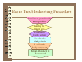
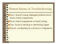
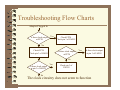
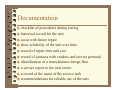
Troubleshooting Techniques
Copyright © 2004
D. L. Gould & Niagara College
Niagara College - Technology
Introduction
Trouble
● The project does not partially or completely
function under all relevant conditions.
Troubleshooting
●An interweaving process of systematic
analysis and testing.
Troubleshooting Tools
● Preliminary testing of the project
● Learning and using the basic electrical and
electronic rules
● Implementing basic Troubleshooting
Procedures
● Using the human senses
● Using troubleshooting guides & flow charts
● Repairing & documenting the test results and
recommendations.
Preliminary Testing
● Preventive maintenance before applying power.
● Confirmation of all component identification
● Visual inspection of the location and orientation
of all components
● Verification of all solder connections.
● Visual checks on all wire ends and insulation
● A wiring check on and off the printed circuit
Electrical/Electronic Rules
● Kirchoff’s Laws: Voltage drops across the loads in a
●
●
●
●
series circuit are equal to the applied voltage. Current
entering a junction will be equal to the current flowing out
of that same junction.
Ohm’s Law: A relationship among voltage, current, and
resistance. One volt applied to a circuit produces one amp
of current flow through one ohm of resistance.
Watt’s Law: A relationship among voltage, current, and
power. Electrical power in a circuit is equal to the product
of the current and voltage in that circuit.
Series Circuit: A circuit that has one path for current flow
Parallel Circuit: A Circuit that has two or more paths for
current to flow.
Basic Troubleshooting Procedure
Familiarize yourself with
unit operation
Identify the
trouble area
Localize the
faulty section
Localize the
faulty circuit
Localize the
faulty component
Repair, Document &
Recommend
Human Senses in Troubleshooting
● Eyes: frayed wiring, damaged printed circuit
traces, burnt components
● Nose: burnt components or burnt wiring.
● Ears: locate a missing or interfering signal
● Touch: overheating in a circuit or component.
Troubleshooting Flow Charts
Adapter Plugged In
Is there clock output
at FPT4
Yes
Check FPT4
Check pin 3 of LM555
No
Check FPT4
Check pin 3 of LM555
Is there clock output
at FPT4
Yes
Is there clock output
at pin 3 of LM555
No
Is there clock output
at pin 3 of LM555
Yes
Check pin 3 of
LM555
No
The clock circuitry does not seem to function
Documentation
● checklist of procedures during testing
● historical record for the unit
● assist with future repair
● show reliability of the unit over time
● record of repair time and cost
● record of contacts with vendors and service personal
● identification of a manufactures design flaw
● a service report to the unit owner
● a record of the name of the service tech
● recommendations for reliable use of the unit.
Summary
● When all else fails read the instructions !
● Basic electrical and electronic rules need to
be learned.
● Remember the basic six step troubleshooting
procedure
● Use your senses.
● Follow the service manual guides
● Document the fault.
Where to get more information
● Electronic Project Design and Fabrication Third
Edition
by Ronald A. Reis
● Troubleshooting Electronic Devices
by Joel Goldberg
● Troubleshooting & Equipment Care
● The Universal Troubleshooting Process