1
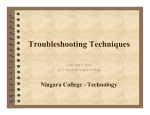
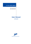
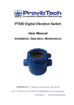
PT500 Electro-Mechanical Vibration Switches
PT500 Electro-Mechanical Vibration Switch
User Manual
Installation, Operation, Maintenance
ProvibTech, Inc.
11011 Brooklet Drive, Suite 300, Houston, Texas 77099, USA
Phone: +1-713-830-7601, Fax: +1-281-754-4972, Email: [email protected], Web: www.ProvibTech.com
PT500-USR-E-A-17
1
ProvibTech
Copy right ProvibTech, 2007
Phone: +1-713-830-7601 Fax: +1-413-793-8109 [email protected] , www.provibctech.com
1
PT500 Electro-Mechanical Vibration Switches
Table of Content
PT500 Electro-Mechanical Vibration Switch Introduction ........................................................................................ 3
PT500 Features ................................................................................................................................................... 3
Specification ....................................................................................................................................................... 3
Physical............................................................................................................................................................... 4
Order Information ............................................................................................................................................... 4
Installation .................................................................................................................................................................. 5
Mechanical Outline Drawings ............................................................................................................................ 5
Installation – Mechanical.................................................................................................................................... 6
Installation - Field-wiring Diagram .................................................................................................................... 6
Operation .................................................................................................................................................................... 8
Principle of electro-mechanical vibration switch................................................................................................ 8
Set-point adjustment ........................................................................................................................................... 9
Maintenance.............................................................................................................................................................. 10
Accessories ....................................................................................................................................................... 10
ProvibTech
Phone: +1-713-830-7601 Fax: +1-413-793-8109 [email protected] , www.provibctech.com
2
PT500 Electro-Mechanical Vibration Switches
PT500 Electro-Mechanical Vibration Switch Introduction
The PT 500 is an economical solution to provide basic
vibration protection for your rotating or reciprocating
machines. The PT 500 uses an inertia sensitive
mechanism which actuates internal micro-switch contacts
when the vibration level exceeds the adjustable setpoint.
The PT 500 start-up delay feature prevents the switch from
activating during the higher vibration levels present during
the start-up of the machine so that the setpoint may be
adjusted closer to the vibration levels present during
normal operation or running speed of the machine.
The PT 500 is your “one stop shopping” for all
Universal mounting
electro-mechanical vibration switch applications. The
9
Local and remote reset
unique design has all industry required environmental and
9
Start up delay
hazardous area approvals. The E-coat option is suitable
9
SPDT, (2) SPDT and gold plated contact options
for offshore and very corrosive environmental applications.
Universal mounting plate will mount in existing mounting
Specification
holes when replacing older mechanical vibration switches.
Function: Armature mechanism trips on
Applications include:
high vibration and operates snap action switch.
Vibration Range: See How to Select “C”
9
Fans
Frequency Range: 0 to 3600 rpm
9
Cooling Motor/Fans
Set Point Adjust: 0 to 100% of range. Internal set point
9
Fin Fans
adjustment.
9
Heat Exchangers
Local Reset: For field local reset of the switch
9
Engines
Remote reset with Start-up Delay: Applying reset coil
9
Reciprocating Compressors
voltage at start up holds mechanism from tripping delay
9
Centrifuges
about 3 seconds, after which the switch is automatically
9
Rock or Coal Crushers
activated.
Reset Coil Power Supply:
PT500 Features
95 ~ 250VAC@100mA, 50~60Hz or
20 ~ 30VDC @ 200mA
Wide operating temperature range of -40°C –
Temperature Limit: -40℃ to +100℃
100°C (-40°F – 212°F)
Enclosure: Casted Aluminum
9
All industry environmental ratings
Environmental Rating : IP65
9
Optional
9
9
NEMA(E-coat),IP65
environmental
Switch Contact(s) Rating:
rating
15A, 125VAC, 250VAC, 480VAC;1/8 HP 125VAC;
Hazardous area agency approvals CSA, ATEX,
1/4 HP 250VAC; 1/2A, 125VDC;1/4A, 250VDC
CE
Gold plated contact: 0.1A 125VAC;0.1A 30VDC
ProvibTech
Phone: +1-713-830-7601 Fax: +1-413-793-8109 [email protected] , www.provibctech.com
3
PT500 Electro-Mechanical Vibration Switches
Hazard Rating: See order information
B: Relay Contact
TR CU : 1Ex d IIC T4T6X
1Ex d llB+H2T4T6 X
№ ТС RU C-US.ГБ05.В.00476
NANIO CCVE
B = 1: SPDT
B = 2: (2)SPDT
ГОСТ 30852.0-2002 (МЭК 60079-0:1998), (кроме п. 27),
ГОСТ 30852.1-2002 (МЭК 60079-1:1998),
ГОСТ 30852.14-2002,
ГОСТ Р МЭК 60079-0-2011 (пп. 29.1-29.3, 29.11).
B = 3: SPDT (gold plated contact)
B = 4: (2) SPDT (gold plated contact)
C: Full Scale
C = 1: 5g
C = 2: 2g
Physical
C = 3: 10g
D: Reset Power with Start-up Inhibit; Local Reset
Temperature
Operation: -40oC ~ + 100oC (-40°F ~ +212°F)
Storage: -50oC ~ + 120oC (-58°F ~ +248°F)
Dimension
See attached drawing
Weight
PT500
1285g (2.8 lbs)
PT500-13
205g
(0.45 Ibs)
PT500-14
279g
(0.6 Ibs)
PT500-15(PT500-17)
440g
(0.97 Ibs)
PT500-20
112g
(0.25 Ibs)
D = 0: Local Reset only
D = 1: Remote Reset and Inhibit; Local Reset
D = 5: Remote Reset and Inhibit; No Local Reset
E: Conduit Entries/Mounting Plate or Mounting Stud
E = 1: 3/4" NPT, Mounting Plate PT500-13
E = 2: 3/4" NPT, Mounting Plate PT500-14
E = 4: M20×1.5, Mounting Plate PT500-14
E = 5: M20×1.5, Mounting Plate PT500-13
E = 6: 3/4" NPT, Mounting Stud 3/4" NPT
E = 7: M20×1.5, Mounting Stud M20×1.5
Order Information
PT500-ABC-DE
A: Hazardous Area Approvals
A = 0: CE Mark
A =1: Multiple Approvals (D=0,1)
CSA: Class l, Div 1, Groups B,C & D T4,T6
ATEX: II 2 G,Ex dⅡB+ H2T4T6
PCEC: Ex dⅡB+ H2T4/T6 Gb
CE Mark
A = 5: Multiple Approvals (D=5)
CSA: Class l, Div 1, Groups A, B, C & D ,T4,T6
ATEX: II 2 G,Ex dⅡC T4T6
PCEC: Ex dⅡC T4/T6 Gb
CE Mark
A = 6: Multiple approvals (D=0,1):
TR CU: 1Ex d llB+H2T4T6 X
CE Mark
A = 7: Multiple approvals (D=5):
TR CU: 1Ex d llС T4T6 X
CE Mark
ProvibTech
Phone: +1-713-830-7601 Fax: +1-413-793-8109 [email protected] , www.provibctech.com
4
PT500 Electro-Mechanical Vibration Switches
Installation
Mechanical Outline Drawings
165(6.5")
135(5.3")
8-R5(0.2")
8(0.31")
165(6.5")
135(5.3")
20(0.79")
8-R5(0.2")
φ108(4.25")
77.7(3.06")
88(3.46")
53.4(2.1")
Mounting
121(4.76")
Holes
3/4"NPT
or M20×1.5
Mounting
Holes
6(0.24")
25(0.98")
5(0.20")
6(0.24")
All dimensions in mm (inches)
PT500-13
PT500-14
PT500-15 (3/4” NPT)
PT500-17 (M20×1.5)
ProvibTech
Phone: +1-713-830-7601 Fax: +1-413-793-8109 [email protected] , www.provibctech.com
5
PT500 Electro-Mechanical Vibration Switches
Installation – Mechanical
PT500 has two different mounting plates and two different mounting studs. See figuration below. Be
aware of that PT500 will sense the vibration in the vertical axis reference to the mounting plate.
Installation - Field-wiring Diagram
Switches
Each switch is SPDT. There are three pin out:
COM:
Common.
NC:
Normally Closed. It is normally connected with the COM. In alarm status, it is
dis-connected from COM.
NO:
Normally Open. It is normally dis-connected with the COM. In alarm status, it is connected
from COM.
ProvibTech
Phone: +1-713-830-7601 Fax: +1-413-793-8109 [email protected] , www.provibctech.com
6
PT500 Electro-Mechanical Vibration Switches
Remote reset with start-up inhibit
Two sets of power supply can be used for this function.
High Voltage(95 ~ 250VAC@100mA, 50~60Hz or 95 ~ 120VDC@100mA): Connect to high
voltage pins. No polarity.
Low Voltage(20~30VDC@200mA): Connect to low voltage pins. No polarity.
Caution:
Never connect the high voltage power into low voltage connectors. It will destroy the reset
circuit!
COM
COM
NO
NO
NC
NC
High Valtage
(GREEN)
Low Valtage
(BLUE)
AC(95-250V)
COM
NO
NO
Relay 1
Shut down
DC(22-30V)
COM
Grounding
ProvibTech
Relay 2
Shut down
NC
NC
Reset Coil Power
High Valtage
Cable Entry
Reset Coil Power
Low Valtage
Phone: +1-713-830-7601 Fax: +1-413-793-8109 [email protected] , www.provibctech.com
7
PT500 Electro-Mechanical Vibration Switches
Operation
Principle of electro-mechanical vibration switch
The spring will hold the vibration plate into the bottom of the frame. Electronic switches are contacted
with the plate.
Support
Set-Point
Adjustment
Vibrating
Plate
Spring
Normal
Alarm
If vibration level overpasses the force exerted by the spring, the vibration plate will flip upward;
electronic switches will be switched on.
F(vibration)=m*a > F(spring) = z*D
Where F is the force; m is the effective mass of the vibration plate; a is the acceleration (vertical);
z is the spring coefficient; and D is the effective displacement of the spring.
The set-point adjustment screw will move the spring up and down. It will in turn change the vertical
component of the force generated by the spring. By adjust the set-point, vibration level is effectively
adjusted.
After the alarm, the spring will force the vibration plate in latching position until the vibration level
decrease to normal and reset is performed.
There are two ways to reset the switch. Local reset will mechanically push the vibration plate down to
normal position.
Remote reset/inhibit will also push the plate to normal position. In addition, it will hold the switch in
non-alarm situation until a 3 seconds delay. This is useful for machine start-up. It will avoid false
alarms.
ProvibTech
Phone: +1-713-830-7601 Fax: +1-413-793-8109 [email protected] , www.provibctech.com
8
PT500 Electro-Mechanical Vibration Switches
Set-point adjustment
9
Mount the switch on machine. Let the machine running.
9
Remove the switch cover. Disconnect any power. Wiring the switch.
9
Push (reset) the vibration plate down to normal position.
9
If the plate flips to alarm position after the reset, adjust the set-point screw clockwise until the
plate back to normal position.
9
Start the machine, when the machine has reached full speed, turn the set-point screw
anti-clockwise slowly till the vibration plate flip to alarm position. Remember the set-point screw
position.
9
Turn the set point clockwise 1g per 45 degree ( 1/8 turns) **. Reset the switch.
9
Mount the switch cover.
Set-Piont
Adjustment
To amplify the ALERT,screw the bolt
according to the arrow direction.
ProvibTech
Phone: +1-713-830-7601 Fax: +1-413-793-8109 [email protected] , www.provibctech.com
9
PT500 Electro-Mechanical Vibration Switches
Maintenance
Accessories
Mounting Plate and mounting studs:
165(6.5")
135(5.3")
165(6.5")
135(5.3")
8-R5(0.2")
8(0.31")
20(0.79")
8-R5(0.2")
φ108(4.25")
77.7(3.06")
88(3.46")
3/4"NPT
or M20×1.5
53.4(2.1")
Mounting
121(4.76")
Holes
Mounting
Holes
25(0.98")
5(0.20")
1
6(0.24")
6(0.24")
All dimensions in mm (inches)
PT500-13
PT500-14
PT500-15 (3/4” NPT)
PT500-17 (M20×1.5)
3/4” NPT seal
3/4” NPT cable feedthrough
Blank cover
Remote reset circuit
PT500-18
PT500-19
PT500-3
PT500-20
ProvibTech
Phone: +1-713-830-7601 Fax: +1-413-793-8109 [email protected] , www.provibctech.com
10