1
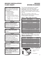
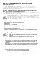
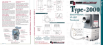
ER3000
Explosion Proof
Manual
www.tescom.com
ER3000 Explosion Proof MANUAL
This manual provides basic installation information and safety precautions for
the following Tescom ER3000 Pressure Controllers:
MODEL NO.
DESCRIPTION
ER3000EI-1
4-20 mAmp/1-5 VDC analog setpoint and feedback
FM Explosion Proof Packaging (Class I,
Division I, Groups B, C, & D)
CSA Explosion Proof Packaging (Class I,
Groups B, C & D, Type 4X)
ER3000EV-1
0 - 10 VDC analog setpoint and feedback
FM Explosion Proof Packaging (Class I,
Division I, Groups B, C, & D)
CSA Explosion Proof Packaging (Class I,
Groups B, C & D, Type 4X)
ER3000MI-1
4-20 mAmp/1-5 VDC analog setpoint and feedback
KEMA ATEX Explosion Proof Packaging (Eex d IIB
+ H2 T4 Hazardous Locations, Category II 2 G)
ER3000MV-1
0 - 10 VDC analog setpoint and feedback
KEMA ATEX Explosion Proof Packaging (Eex d IIB
+ H2 T4 Hazardous Locations, Category II 2 G)
ER3000GI-1
Same as ER3000EI-1 with the addition of 2
analog/digital inputs, 2 digital outputs and 1 analog
sensor output
ER3000GV-1
Same as ER3000EV-1 with the addition of 2
analog/digital inputs, 2 digital outputs and 1 analog
sensor output
ER3000NI-1
Same as ER3000MI-1 with the addition of 2
analog/digital inputs, 2 digital outputs and 1 analog
sensor output
ER3000NV-1
Same as ER3000MV-1 with the addition of 2
analog/digital inputs, 2 digital outputs and 1 analog
sensor output
ER3000P
Same as ER3000MI-1 with screw terminal strip
style and 2 additional analog inputs
ER3000H
Same as ER3000EI-1 with screw terminal strip
style and 2 additional analog inputs
1
TABLE OF CONTENTS
Introduction . . . . . . . . . . . . . . . . . . . . . . . . . . . . . . . . . . . . . . . . . . . . . . 3
Hazardous Locations Certifications . . . . . . . . . . . . . . . . . . . . . . . . . . 4
Specifications . . . . . . . . . . . . . . . . . . . . . . . . . . . . . . . . . . . . . . . . . . . . 5
Enclosure . . . . . . . . . . . . . . . . . . . . . . . . . . . . . . . . . . . . . . . . . . . . . . 5
Media . . . . . . . . . . . . . . . . . . . . . . . . . . . . . . . . . . . . . . . . . . . . . . . . . 5
Inlet Pressure . . . . . . . . . . . . . . . . . . . . . . . . . . . . . . . . . . . . . . . . . . . 5
Environment . . . . . . . . . . . . . . . . . . . . . . . . . . . . . . . . . . . . . . . . . . . . 5
Flow Rate . . . . . . . . . . . . . . . . . . . . . . . . . . . . . . . . . . . . . . . . . . . . . . 5
Power Requirement . . . . . . . . . . . . . . . . . . . . . . . . . . . . . . . . . . . . . . 5
RS485 Communication Interface . . . . . . . . . . . . . . . . . . . . . . . . . . . . 5
Accuracy . . . . . . . . . . . . . . . . . . . . . . . . . . . . . . . . . . . . . . . . . . . . . . . 5
Response Time . . . . . . . . . . . . . . . . . . . . . . . . . . . . . . . . . . . . . . . . . . 6
Ports . . . . . . . . . . . . . . . . . . . . . . . . . . . . . . . . . . . . . . . . . . . . . . . . . . 6
Weight . . . . . . . . . . . . . . . . . . . . . . . . . . . . . . . . . . . . . . . . . . . . . . . . . 6
External Analog Input Impedance . . . . . . . . . . . . . . . . . . . . . . . . . . . 6
Digital Outputs . . . . . . . . . . . . . . . . . . . . . . . . . . . . . . . . . . . . . . . . . . 6
Digital Inputs . . . . . . . . . . . . . . . . . . . . . . . . . . . . . . . . . . . . . . . . . . . . 6
Analog Output . . . . . . . . . . . . . . . . . . . . . . . . . . . . . . . . . . . . . . . . . . . 6
Sensor Update Rate . . . . . . . . . . . . . . . . . . . . . . . . . . . . . . . . . . . . . . 6
ER3000 Installation Flow Chart & ER3000 Wiring Diagram . . . . . . . 7
Safety, Installation, & Operation Precautions . . . . . . . . . . . . . . . . . . 8-10
Safety Precautions . . . . . . . . . . . . . . . . . . . . . . . . . . . . . . . . . . . . . . . 8-10
Installations . . . . . . . . . . . . . . . . . . . . . . . . . . . . . . . . . . . . . . . . . . . . . 10
Repair Service . . . . . . . . . . . . . . . . . . . . . . . . . . . . . . . . . . . . . . . . . . 10
Safe Component Selection . . . . . . . . . . . . . . . . . . . . . . . . . . . . . . . . . 11
Assembly/Installation/Wiring Drawings & Bills of Materials . . . . . . 11
2
Introduction
The ER3000 Series (Electronic Regulator) is a versatile 0 to 100 PSIG pressure
controller. It can be used in conjunction with any pneumatically actuated
regulator or valve to control pressure.
Setpoints can be provided via an analog input (4-20mA, 1-5V, or 0-10V), the
digital RS485 interface, or a downloaded profile.
The controller can be wired through a standard serial communication port using
an RS232 to RS485 adapter. This communication channel also provides for the
programming of a number of internal parameters, including PID tuning variables,
zero and span, mode of operation, limits, etc.
Feedback can be derived either from the ER3000’s internal temperature
compensated sensor or an external transducer (4-20mA, 1-5V, or 0-10V).
Four modes of operation are available:
1. Internal feedback mode makes the controller an I/P when analog
setpoints are used and uses the internal sensor as the source of
feedback.
2. External feedback mode uses an external sensor as the feedback.
3. Cascade mode creates a loop within a loop; the inner loop uses the
internal sensor for feedback and the outer loop uses the external
transducer for feedback.
4. Manual mode allows for direct control of the solenoid valves (used for
troubleshooting the system only).
3
Hazardous Locations Certifications
Factory Mutual (FM) Approval:
Explosion Proof
Identification No. 2Z0A0.AE
Class I, Division I, Groups B, C, and D
Enclosure type 4X
SPECIAL CONDITIONS FOR SAFE USE
– -20°C ≤ Tamb ≤ 60°C
– Do not remove cover while circuits are live
– Installation to be in accordance with the latest edition of National
Electrical Code
– Unused conduit entry must be closed with suitable blanking element
– Seal conduit within 18 inches
Canadian Standards Association (CSA)
Explosion proof
Certification No. LR 85614-4
Class I, Groups B, C, and D
Enclosure Type 4X
SPECIAL CONDITIONS FOR SAFE USE
– -20°C ≤ Tamb ≤ 60°C
– Do not remove cover while circuits are live
– Installation to be in accordance with the latest edition of Canadian
Electrical Code
– Rated 24 VDC, 350 mAmps
– Maximum working pressure: 110 psig
KEMA/Cenelec
Flameproof Certification
Certificate No. KEMA 03ATEX2365
ATEX Marking: EEx d IIB + H2T4
Category: II 2 G
Enclosure type IP65
SPECIAL CONDITIONS FOR SAFE USE
– -20°C ≤ Tamb ≤ 60°C
– Do not remove cover while circuits are live
– Installation to be in accordance with the applicable local
requirements
– The cable and conduit entry devices shall be of certified flameproof
types, suitable for the conditions of use and correctly installed
– Unused apertures shall be closed with certified flameproof blanking
elements
4
Specifications
Enclosure
NEMA 4X / IP65.
To prevent any interference from electromagnetic radiation, use rigid
metal conduit to enclose the wiring entering the ER3000. Two 1/2" NPT
wire ports have been provided for this purpose. If unused, properly seal
with a metal plug.
Media
The preferred media is clean, dry instrument grade air or nitrogen. Use
of an in-line 40-micron filter is highly recommended to prevent damage to
the solenoid valves.
Inlet Pressure
Minimum:
Maximum:
Typical:
Note: Response time
Outlet pressure + 1 PSIG
120 PSIG
110 PSIG
is affected by inlet pressure.
Environment
Temperature:
Pressure:
Humidity:
-20°C to 60°C (dry nitrogen supply gas)
5°C to 60°C (shop air)
28 - 32 inches Hg
To 100% R.H. (non-condensing) @ 0°C to 60°C
Flow Rate
Cv: 0.01
Note: The flow rate can be increased through the use of a booster
regulator.
Power Requirement
Voltage:
Current:
24 VDC (22 VDC to 28 VDC)
340mA maximum, 180mA nominal
RS485 Communication Interface
Networking:
Cable length:
Baud rate:
Up to 32 controllers on one network
4000 ft. maximum
9600
Accuracy
Room temp:
0.1% of span maximum
Temperature effects: 0.002%/°F of span maximum
Note: Accuracy is based on the user-provided external transducer when
used in external feedback mode.
5
Response Time
Rise Time:
257ms. - 10 PSIG to 90 PSIG
Fall Time:
552ms. - 90 PSIG to 10 PSIG
Note: Step response into dead-end system (1 cubic inch volume).
Ports
Conduit:
Pneumatic:
1/2" NPT
1/8" NPT - Inlet, exhaust and gauge ports
1/4" NPT - Controlled outlet port
Weight
40.6 oz. (1.15 kg)
External Analog Input Impedance
4-20mA:
1-5V:
0-10V:
250Ω
220KΩ - Single input pin to ground
1.7MΩ - Differential input
100KΩ
Digital Outputs
Current:
Voltage:
Type:
50 mA Continuous, 100 mA Instantaneous
5V - 28V
Open collector, grounded emitter
Digital Inputs
Voltage Range/Input Impedance:
4-20 mA: 250Ω
1-5V:
220KΩ - Single input pin to ground
1.7MΩ - Differential input
0-10V: 100KΩ
Type:
Level sensitive
Analog Output
4-20mA:
0.5% Accuracy
Sensor Update Rate
25ms:
6
Rate of sensor reading and processing task
ER3000 Installation
Flow Chart
Step 1: Select Voltage/Current
Jumper J5 (top board – see below
right for Figure 1) – Select Jumper
position* for:
1: Analog Setpoint
2: External Feedback
3: Auxiliary input #1
4: Auxiliary input #2
For all the above jumper positions:
• Jumper not installed: configured
for 1-5V.
• Jumper installed: configured for
4-20mA.
*Not on 0-10V models
Step 2: Plumb the external
regulator and transducer
Use safety information on pages 4-6
& 8-10 prior to pressurization and
operation of all equipment.
Step 3: Mount the ER3000
Four 8-32 UNC screw holes are
provided.
ER3000
Wiring Diagram
The following tables give the complete
wiring layout of the ER3000 wiring
assemblies, which are connected to the
J3 and J4 terminal blocks. Refer to the
tables to ensure proper wiring of external
devices.
Note: The (+) and the (-) refer to the
differential inputs. Both must be connected
for the system to work properly.
Table 1: Main Cable Assembly*
J3 Pins
1
2
3 4
5
6
7
8
9
10
11
12
Description
Color
+Setpoint Input
-Setpoint Input
+Feedback Input
-Feedback Input
-RS485 Network connection
+RS485 Network connection
+ 24 Volt DC Power
24 Volt Return, (Power Ground)
+5 Volt output (5mA max.)
Analog Signal Ground
Analog Signal Output
Analog Signal Ground
Brown
Red
Orange
Yellow*
Green
Blue
Violet
Gray
White
Black
Pink
Tan*
*The tan wire should be connected to the yellow wire
in systems with 4-20mA feedback.
Step 4: Electrical wiring
Connect ER3000 to a power supply,
transducer, and computer (if needed),
using the tables on this page.
Note: All electrical wiring must be
in accordance with applicable local
standards (see pages 4-6 & 8-10).
Step 5: Tune program (if using
a computer)
Download the Tune program onto
your computer.
Step 6: Read and follow the
safety sections on page 4-6
& 8-10 carefully prior to
pressurization and operation
of the system.
Table 2: Auxiliary Cable Assembly
(ER3000F/ER3000G)
J4 Pins
1
2
3 4
5
6
7
8
Description
Color
+Auxiliary Input #1
-Auxiliary Input #1
+Auxiliary Input #2
-Auxiliary Input #2
Analog Signal Ground
Analog Output Ground
Digital Output #1
Digital Output #2
Brown
Red
Orange
Yellow
Green
Black
Blue
White
Figure 1: Top Board
J3 & J4 Terminal
Blocks
J5 Jumpers
7
Safety, Installation, & Operation
Precautions
DO NOT ATTEMPT TO SELECT, INSTALL, USE, OR MAINTAIN THIS
CONTROLLER, OR ACCESSORY UNTIL YOU HAVE READ AND FULLY
UNDERSTOOD THESE INSTRUCTIONS.
BE SURE THIS INFORMATION REACHES THE OPERATOR AND STAYS
WITH THE PRODUCT AFTER INSTALLATION.
DO NOT PERMIT UNTRAINED PERSONS TO INSTALL, USE, OR MAINTAIN
THIS CONTROLLER, OR ACCESSORY.
IMPROPER SELECTION, IMPROPER INSTALLATION, IMPROPER
MAINTENANCE, MISUSE, OR ABUSE OF THIS CONTROLLER, OR
RELATED ACCESSORIES CAN CAUSE DEATH, SERIOUS INJURY,
AND/OR PROPERTY DAMAGE.
Possible consequences include but are not limited to:
•
•
•
•
•
•
•
High velocity fluid (gas or liquid) discharge
Electrocution
Parts ejected at high speed
Contact with fluids that may be hot, cold, toxic, or otherwise injurious
Explosion or burning of the fluid
Lines/hoses whipping dangerously
Damage or destruction to other components or equipment in the system
Safety Precautions
3.
4.
5.
6.
7.
8.
8
1. Read and understand the user’s manual before operating the
controller.
2. Inspect the controller, and accessories before each use.
Operate the unit only under specified environmental conditions.
Follow instructions in the manuals for proper wiring.
Never connect the controller, or accessories to a supply source having
a voltage greater than the maximum rated voltage of this controller, or
accessory.
Never connect the controller, or accessories to a supply source having a
pressure greater than the maximum rated pressure of this controller, or
accessory.
Never use anything but clean dry inert gases or air into the
electropneumatic controller.
Start up sequence for electropneumatic controllers is:
a. Feedback loop must be installed and operational.
b. Electrical power should be applied and system setpoint reduced to its
lowest pressure output before turning on the pneumatic supply to the
controller.
9. Refer to product label (modification specific) for maximum inlet pressures.
If this rated pressure cannot be found, contact your local Tescom
representative for the rated pressure prior to installation and use. Verify
the designed pressure rating of all equipment (e.g., supply lines, fittings,
connections, filters, valves, gauges, etc.) in your system. All must be
capable of handling the supply and operating pressure.
10. Clearly establish flow direction of the fluid before installation of controllers,
regulators, valves, and accessories. It is the responsibility of the user to
install the equipment in the correct direction.
11. Do not tighten fittings, gauges, or components in pressurized systems.
12. Never turn controller, regulator or valve body. Instead, hold the controller
body and turn fitting nut.
13. If a controller, regulator or valve leaks or malfunctions, take it out of service
immediately.
14. Do not modify equipment or add attachments not approved by the
manufacturer.
15. Apply pressure to the system gradually, avoiding a sudden surge of fluid or
pressure shock to the equipment in the system.
16. Regulators are not shut-off valves. Install a pressure relief device
downstream of the regulator to protect the process equipment from
operating pressure increases. Shut off the supply pressure when the
regulator is not in use.
17. Periodic inspection and scheduled maintenance of your equipment is
required for continued safe operation.
18. The frequency of servicing is the responsibility of the user based on the
application. Never allow problems or lack of maintenance to go unreported.
19. Read and follow precautions on compressed gas cylinder labels.
20. It is important that you analyze all aspects of your application and review all
available information concerning the product or system. Obtain, read, and
understand the Material Safety Data Sheet (MSDS) for each fluid used in
your system.
21. Oxygen service requires special expertise and knowledge of system design
and material compatibility in order to minimize the potential for death,
serious injury, and/or property damage.
22. Never use materials for controllers, regulators, valves, or accessories that
are not compatible with the fluids being used.
23. Users must test under normal operating conditions to determine suitability of
materials in an application.
24. Vent fluids to a safe environment, and in an area away from employees.
Be sure that venting and disposal methods are in accordance with
Federal, State, and Local requirements. Locate and construct vent lines
to prevent condensation or gas accumulation. Make sure the vent outlet
is not obstructed by rain, snow, ice, vegetation, insects, birds, etc. Do not
interconnect vent lines; use separate lines if more than one vent is needed.
9
25. Do not locate controllers, regulators, valves, or accessories using flammable
fluids near open flames or any other source of ignition. Use of Explosion
Proof controllers may be necessary to be in accordance with local electric
codes.
26. Some fluids, when burning, do not exhibit a visible flame. Use extreme
caution when inspecting and/or servicing systems using flammable fluids
to avoid death or serious injury to employees. Provide a device to warn
employees of these dangerous conditions.
27. Many gases can cause suffocation. Make certain the area is well ventilated.
Provide a device to warn employees of lack of oxygen.
28. Never use oil or grease on these controllers, regulators, valves, or
accessories. Oil and grease are easily ignited and may combine violently
with some fluids under pressure.
29. Have emergency equipment in the area if toxic or flammable fluids are
used.
30. Upstream filters are recommended for use with all fluids and gases.
31. Do not bleed system by loosening fittings.
32. Prevent icing of the equipment by removing excess moisture from the gas.
33. Always use proper thread lubricants and sealants on tapered pipe threads.
Installations
Inspect the controller, and accessories for physical damage and contamination.
Do not connect the controller, or accessory if you detect oil, grease, or damaged
parts. If the controller, or accessory is damaged, contact your local Tescom
representative to have the controller cleaned or repaired.
Make sure that the components and materials used in the fluid
handling system are compatible with the fluid and have the proper
pressure rating.
Make sure that the components used in the electronic system are
compatible with and have the proper voltage rating.
Repair Service
If a controller leaks or malfunctions, take it out of service immediately. You
must have instructions before doing any maintenance. Do not make any
repairs you do not understand. Have qualified personnel make repairs. Return
any equipment in need of service to your equipment supplier for evaluation
and prompt service. Equipment is restored to the original factory performance
specifications, if repairable. There are flat fee repair charges for each standard
model. The original equipment warranty applies after a complete overhaul.
10
Safe Component Selection
3.
4.
5.
6.
1. Consider the total system design when selecting a component to
ensure safe, trouble-free performance.
2. The user is responsible for assuring all safety and warning
requirements of the application are met through his/her own
analysis and testing.
Tescom may suggest material for use with specific media upon request.
Suggestions are based on technical compatibility resources through
associations and manufacturers. Tescom does NOT guarantee materials to
be compatible with specific media — THIS IS THE RESPONSIBILITY OF
THE USER!
Component function, adequate ratings, proper installation, operation, and
maintenance are the responsibilities of the system user.
The user is responsible to be in accordance with all the necessary
mechanical and electrical codes required for installation and operation of the
system. These requirements include but not limited to all explosion proof
controllers.
The user is responsible for the selection of the proper model number of the
controller that would meet the application’s possible hazardous environment
or conditions.
Do not modify equipment or add attachments not approved
by the manufacturer.
ASSEMBLY/INSTALLATION/WIRING DRAWINGS &
BILLS OF MATERIALS
Drawings and parts lists for your product may be obtained by calling the
number below. Tescom will provide these by fax or mail. Your local Tescom
representative can provide additional assistance.
Call (800) 447-1250 or email to [email protected] for assembly/
installation/wiring drawings & bills of materials. Be sure to have your
complete model number ready.
11
Tescom
Industrial Controls
Systems Group
12616 Industrial Boulevard
Elk River, Minnesota 55330-2491
Toll Free 800-447-1250
Tel
763-241-3238
Fax
763-241-3224
e-mail: [email protected]
www.tescom.com
Form No. 1960
Rev. 4/06
Printed 4/06
150
Printed in U.S.A.