1
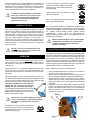
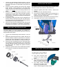
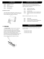
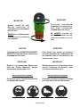
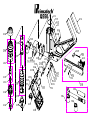
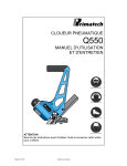
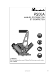
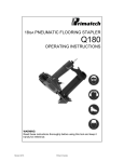
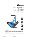
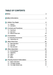
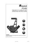
PNEUMATIC FLOORING NAILER Q550 OPERATING INSTRUCTIONS WARNING Read these instructions thoroughly before using this tool and keep it handy for reference. Revision 03/10 Printed in Canada 9. PRIMATECH PNEUMATIC NAILER Q550 10. 11. The pneumatic nailer Q550 is a professional precision tool specially developed for the installation of 3/8" to 3/4" solid and engineered hardwood flooring. It has been designed for easy maintenance where major components can be accessed within seconds without the need of any tool. Weighting only 8.7 pounds (4 kg), this ergonomically designed tool makes the installation of hardwood floor very easy, allowing the operator to set and nail the boards in the standing position. It uses standard L- type 18GA cleats available in lengths of 1¾" (45 mm), 1½" (38 mm) and 1¼" (32 mm). For best result, only PRIMATECH cleats should be used. Read carefully these instructions before operating this tool. It is important to understand warnings/cautions and the safety measures to ensure safe use of this tool. The Q550 is built around the Primpact valve engine, a breakthrough technology for pneumatic tools. Primpact main features are: • • • • short nose and compact valve design with an allaround striking surface high-speed action and few moving parts, for a powerful yet soft stroke and increased precision. reciprocal striking system that regulates the depth of penetration independently from the mallet impact finely threaded screw-in cartridge assembly Additional information is available directly from the manufacturer: 12. 13. 14. Never service or repair the tool, clear obstructions or make adjustments while the air supply hose is connected. Only compressed air should be used to power this tool ; do not exceed 110 psi (7.6 bar). Never use oxygen or any other compressed gas as a power source for this tool. Always wear OSHA-required Z-87 safety glasses with side shields. Always wear proper ear and feet protection while the air supply hose is connected. Always remove cleats from the feeder channel before servicing tool. DO NOT REMOVE OR ALTER SAFETY. NEVER DEPRESS THE SAFETY CONTACT WITH YOUR HANDS WHEN TOOL IS CONNECTED TO AIR SUPPLY. EXTREME CAUTION IS ADVISED WHEN USING THIS TOOL. CONNECTION & AIR SUPPLY SYSTEM To ensure maximum performance and efficiency, and also a minimum of care, the PRIMATECH pneumatic nailer requires clean, dry air. It is necessary to use a filter and a pressure regulator. This tool needs a detachable male coupler with 3/8" NPT male treads. The use of a 3/8" (1 cm) diameter air supply hose is recommended. A smaller hose or a hose longer than 50' (15 m) could cause a pressure drop when the tool is activated repeatedly. ALWAYS USE A FREE-FLOW CONNECTION FOR THE COMPRESSED AIR SUPPLY TO PREVENT THAT THE TOOL STAYS CHARGED AFTER DISCONNECTING THE AIR SUPPLY HOSE. UNLOAD TOOL BEFORE CONNECTING AIR TO PREVENT ACCIDENTAL DISCHARGE. 1135 Jeremie-Fortin, Quebec, QC Canada, G1J 1R8 Phone: Fax: email: web: 1 (800) 363-1962 or 1 (418) 522-7744 1 (418) 522-7466 [email protected] www.primatech.ca/support SAFETY MEASURES These important guidelines should always be followed to work safely with the PRIMATECH pneumatic nailer model Q550: 1. 2. 3. 4. 5. 6. 7. 8. Read these instructions thoroughly before using this tool and keep it handy for reference if necessary. Always keep hands, feet or other body parts away from the nail ejection area. Never aim the tool in any direction other than the working area. Always carry or manipulate the tool by its handle while the air supply hose is connected. Never hit the head cap of the actuator if the plastic base is not sitting perfectly on the working surface. Never leave the tool laying down on its side while the air supply hose is connected; the tool should always be left on the floor, standing on its plastic base. Do not alter or remove safety. Always disconnect the air supply hose when the tool is not in use or when move to another work area. AFTER MOVING TOOL TO A DIFFERENT WORK AREA, OR AFTER ANY MAINTENANCE TO THE TOOL, ALWAYS ENSURE PROPER OPERATION BY ACTUATING TOOL SEVERAL TIMES WITHOUT CLEATS OVER THE SUBFLOORING . Dirt, dust, and other particles in the air supply can cause sluggish operation or premature wear of many components of the tool. Drain water from the compressor tank regularly. The compressor start-stop limits should be set to deliver an air pressure of at least 100 psi (7 bar) at all time. Consult the compressor manual or dealer for instructions on how to make this adjustment. At 80 psi (5.5 bar) and 100 hits per minute, the tool consumes approximately 3.8 cu.ft (110 ) of air per minute at 70°F (21°C). Higher air pressure will increase the consumption of compressed air. The tool is designed to be operated with a compressed air pressure of 80 psi (5.5 bar). Occasionally, a higher pressure could be necessary, for example to use the tool with different species of harder wood. In these more difficult cases, the compressed air pressure can be increased up to 100 psi (7.0 bar). It is very important not to exceed this maximum pressure to prevent leaks, premature wear or damages to the tool. Check the compressed air supply hose before connecting to ensure that they are free from dirt or particles that can alter the performance of the tool. Pay special attention to any air leaks. Do not use a compressed air pressure higher than 110 psi (7.6 bar). Higher pressure can cause premature wear or damage to certain components. After assembly, check all the connections to prevent the leaks and to have maximum efficiency. TO PREVENT ACCIDENTAL DAMAGE TO THE FINISHED SURFACE OF THE INSTALLED FLOOR, REST THE TOOL ONTO THE SUBFLOORING WHEN CONNECTING AIR, LOADING TOOL WITH NAILS OR PERFORMING ANY MAINTENANCE TO THE TOOL. LOADING THE TOOL Insert a row of PRIMATECH's cleats inside the feeder channel and pull back on the plastic tab gently until it engages behind the cleats. To release, simply squeeze the tab with your thumb and index and allow the spring to recoil slowly. The clip must be released slowly to prevent damage. The Q550 uses standard Ltype 18GA cleats available in lengths of 1¾" (45 mm), 1½" (38 mm) and 1¼" (32 mm). Make sure that the proper type of cleats is used. Primatech's 18GA cleats are packaged into green color-coded boxes. For MAXIMUM PERFORMANCE, always use PRIMATECH cleats. USE ONLY THE TYPE OF CLEATS IDENTIFIED ON THE FEEDER CHANNEL. THE USE OF ANY OTHER TYPE OF CLEATS WILL DAMAGE THE TOOL. OPERATION Unload tool and rest it onto the subflooring, Connect the hose and cycle tool once or twice without nails. After loading the tool with PRIMATECH cleats, the PNEUMATIC NAILER model Q550 is ready for use. Only use the 2.5 lbs (1.1 kg) hammer supplied with the tool. The use of other type of hammers may affect performance. The rubber face of the hammer can be used with care to help position the boards. With the flooring firmly in place, position the tool onto the flooring, with the resting block Q-034 against the tongue. Apply downward pressure to ensure proper seating of the cleat. Strike the head cap Q-001 with the hammer to activate the tool, Use only the RUBBER FACE of the hammer to activate the tool. Using the steel end will damage the tool and void the warranty. If wood is slightly twisted, hitting the tool with more force will assist in pulling the board up snugly. NEVER strike the head cap when the tool is not sitting on the working surface. OPERATING THE TOOL WHEN THE SAFETY CONTACT IS NOT FULLY DEPRESSED WILL CAUSE PREMATURE WEAR OR DAMAGE TO THE DRIVING BLADE, PISTON AND CYLINDER. Eye protection is recommended and should be worn by the operator and other in working area. Accidental ejection of nails or wood debris could cause severe eye injury. In some environments, ear protection might be required, as working condition may include exposure to high noise levels which lead to hearing damage. Wearing safety boots and safety hat is also highly recommended. NOTE: All the personal protection equipments must meet national standards. Be it raw, factory finished or engineered, hardwood is a natural material subject to various factors, such as humidity, subflooring, installation procedure, type of tools, fasteners, etc. Installer should always ensure optimal surface pr epar ation, c om ply with all m anufactur er 's recommendations and conduct a pre-installation test prior beginning any installation. BEFORE STARTING AN INSTALLATION, FASTEN DOWN FEW BOARDS TO ASCERTAIN THAT YOU ARE USING THE RIGHT FASTENER AND THAT THE TOOL IS PROPERLY ADJUSTED. ADJUSTING FOR HARDWOOD THICKNESS The Q550 pneumatic nailer is fitted with a fully adjustable plastic base Q-033, designed to prevent contact with the top edge of the flooring. Since there is no standard among manufacturers about the dimensions of the tongue, it is important to adjust the nailer to fit the flooring prior any installation. The Q550 also features a resting block Q-034 which prevent damage to the top edge of the flooring by positioning the tool against the tongue, preventing the gate/foot assembly from contacting the board. Step 1: adjusting the base for flooring thickness: Using the supplied Allen wrench, loosen but do not remove screws (A); one on each side of the tool. With the tool in an upside down position, place a short piece of flooring against the gate/foot assembly (Q-029/Q-032). Engage the Allen wrench in knob (B) as shown; rotate to move the base up or down. Note that knob (B) has a rotation range of only about 1/2 turn. Do not apply force when a limit is reached. Adjust the height of the plastic base to obtain a small gap between the gate/foot assembly and the top side of the tongue of the sample board. A gap of 1/32", about half the thickness of the nail, should be adequate for most situations. Tighten both screws (A). Step 2: adjusting the resting block for the width of the tongue: Using the Allen wrench, loosen by about 1/2 turn n do not remove the two screws (C). With the short piece of flooring still against the gate/foot assembly, adjust the gap between the resting block and the tongue with screw (D). A small gap of 1/32", about half the thickness of the nail, should be adequate for most situations. Tighten both screws (C). Ensure that screw (D) is slightly tighten. Do not apply force on screw (D) once screws (C) are tighten. After completing the adjustment procedure, proceed with the installation of few boards. Carefully check for the proper positioning of the nail onto the board. Check again after few more rows to insure that all parts are secured in place. Tool may lose adjustment over time if this procedure is not strictly followed. BEFORE STARTING AN INSTALLATION, NAIL DOWN FEW BOARDS TO ASCERTAIN THAT YOU ARE USING THE RIGHT TOOL AND FASTENER. PREVENTIVE MAINTENANCE This tool requires minimal lubrication. Use only detergent-free oil such as Primatech P-090. Few drops of oil weekly in the air inlet is sufficient. Other types of lubricant may degrade the seals. Check periodically to make sure that all screws are tight. Pay particular attention to the two screws holding the feeder channel as well as the screws and nuts on the feeder channel assembly who might loosen up over time. Be careful not to strip the threads when tightening. The use of an medium strength adhesive sealant such as the Loctite 242 is recommended for those screws and nuts. MAINTENANCE & REPAIR Most adjustments to the tool can be made with the 3/16" and 5/32" Allen wrench supplied with the tool. These can be conveniently stored above the feeder channel Q-048. Disassembly of the tool must be done in a clean environment. Some parts can be easily damaged if disassembled with improper tools or by inadequate methods. Maintenance should only be performed by trained personnel. Use only genuine PRIMATECH replacement parts. TO PREVENT INJURY, ALWAYS DISCONNECT THE AIR SUPPLY HOSE WHEN SERVICING OR DISASSEMBLING THE TOOL. When servicing the tool, do not twist or force any parts. Damage may result from such abuse. If parts do not come loose easily, contact your PRIMATECH distributor for more information. When opening the tool for maintenance, always clean all components of dirt, grit, or particles. Inspect the tool carefully for broken parts or excessive wear, and replace if necessary. When ordering parts, be sure to specify the right part number, and also the tool serial number. NEVER apply threadlocker or adhesive onto cylinder or head threads. AFTER ANY MAINTENANCE TO THE TOOL, REMOVE ALL CLEATS BEFORE CONNECTING AIR AND ACTUATE THE TOOL REPEATEDLY OVER A PIECE OF WOOD OR SUBFLOORING TO INSURE PROPER OPERATION. ASSEMBLING THE VALVE All the components required to drive nails in and reset the tool are packed in a cartridge assembly which is simply inserted into the tool. This section describes how to assemble all the components together. However, it is usually not necessary to completely disassemble the valve. Refer to next section, "CLEANING THE VALVE" for more information on how to open the tool for regular maintenance. The following procedure assumes that the gate/foot assembly (Q-029/Q-032) along with the resting block Q-034 are already installed. Refer to the "Replacement Parts" document for a complete list and schematic of the tool. 1. 2. 3. 4. 5. 6. 7. It is usually not required to separate the head disk Q-001A from the head cap Q-001. If necessary, insert the head disk Q-001A firmly in place into the head cap Q-001. Align the inner shape of the head cap Q-001 with the shape of the head Q-006 and snap the cap in place. It is usually not required to remove the head cap from the head. Check the condition of all rings and seals on the actuator Q-042, actuator cap Q-044 and main valve Q-043. Lightly lubricate actuator Q-042 as shown and insert it into valve Q-043. Lightly lubricate the permanent seal of actuator cap Q-044 as shown. Do not lubricate the small o-ring (see part Q-044C on schematic). Insert the actuator cap as shown and forcibly snap it into the actuator Q-042 Insert the valve sub-assembly completely into the head Q-006. Check that the band-valve Q-018A is properly installed onto the main cylinder Q-018. Screw the cylinder Q-018 completely onto the head body Q-006 and tighten firmly by hand. Take care not do damage the threads. Pull down the valve Q-043 to sit it onto the cylinder. ALWAYS CHECK THAT THE CYLINDER IS COMPLETELY SCREW-ON THE HEAD BEFORE INSERTING THE ASSEMBLY INTO THE TOOL. THE CYLINDER WILL LOOSEN-UP WHEN THE CARTRIDGE IS TAKEN-OFF THE TOOL. ALWAYS PULL DOWN THE VALVE AGAINST THE CYLINDER BEFORE INSERTING THE HEAD ASSEMBLY. 8. Check that the piston sub-assembly, including rings and driving blade, is sliding easily into the cylinder Q-018. It should offer some resistance, but if it moves too easily, it may be required to replace the piston wear-ring Q-022A. 9. Insert the seal bushing Q-025B in the lower section of main body Q-006 and engage it onto the upper portion of the gate/foot assembly (Q-029/Q-032). A flat screwdriver can help location the seal bushing correctly. Use the wooden handle of the hammer to tap the seal bushing completely in place. It is usually not necessary to pull-out the seal bushing Q-025B for maintenance. 10. With the tool in the upright position, push the bumper Q-025A in place, indexed onto the seal bushing Q-025B and use the wooden handle to seat the bumper in position. 11. Insert the piston sub-assembly into the main body Q-016 and engage the driving blade Q-023 in the seal bushing opening. Depress the safety contact Q-062 to ensure that the driving blade has engaged the gate/foot assembly guiding channel. Complete 'cartridge' assembly 12. Loosen the lock P-616D and insert the whole head assembly into the main body Q-016; the main cylinder Q-018 engaging onto the piston assembly. Screw the head assembly completely. Take care not do damage the threads. Rotate the lock clockwise and tighten with the Allen key using moderate force. NEVER APPLY THREADLOCKER OR ADHESIVE ONTO CYLINDER OR HEAD THREADS. IT IS MOST IMPORTANT THAT THE MAIN CYLINDER BE FULLY SCREWED & TIGHTENED ONTO THE HEAD ASSEMBLY BEFORE BEING INSERTED INTO THE MAIN BODY. AFTER REASSEMBLY, ALWAYS ACTUATE THE TOOL REPEATEDLY WITHOUT CLEATS AGAINST A PIECE OF WOOD TO INSURE PROPER OPERATION. This tool features a head lock to maintain firmly in place the head assembly during operation. Before inserting the head assembly, ensure that the P-616D lock is free to swivel and rotate it away from the head opening. After inserting the head assembly in place, rotate the P-616D lock and tighten with the Allen key using moderate force. To remove the head assembly, simply unscrew the P-616D screw ¼ turn and rotate it counter-clockwise. CLEANING THE VALVE If the tool becomes sluggish or does not set the cleat, it may indicate excessive dirt, dust, other particles, or even water, in the head assembly, thereby impeding the cycling of the valve. The first step in troubleshooting is to clean up the head assembly. 1. 2. 3. 4. 5. Unscrew the head assembly Q-006 and take it out of the tool. The long arm of a Allen wrench may be inserted into one of hole at the base of head Q-006 to help unlock the assembly. Pull-out the piston assembly and unscrew the cylinder Q-018. Perform a visual inspection of the driving blade Q-023, the wear-ring Q-022A and the inner surface of the cylinder Q-018. Do not remove the driving blade from the piston. Pull-out the valve assembly Q-043 and perform a visual inspection of all rings. Check that the actuator assembly Q-042/Q-044 is sliding easily on valve Q-043. Clean and lubricate lightly. It is usually not necessary to take apart the actuator assembly. If necessary, actuator cap Q-044 may be unsnapped from actuator Q-042 by inserting the long arm of an Allen wrench through the hole on top of the actuator and using a hammer with moderate force to get the parts apart. Clean the inside wall of the head body Q-006 and lubricate lightly with a non-detergent oil. Check the o-ring Q-006A. It is generally not necessary to remove the head cap Q-001. INSTALLING THE SAFETY You shouldn't need to remove the safety stop mechanism unless the element Q-061 do not swivel or has a broken tip. a) b) c) d) e) Assemble together parts Q-061, Q-061A , Q-061C and Q-061D. Insert the short end of Q-061B as shown. Put two drops of adhesive sealant onto the thread area of Q-061C, near its cylindrical end. Make sure no sealant is retained on the end or exterior wall. Insert the assembly into the hole in the tool body as shown. Tight together with screw P-153A, holding Q-061C. REPLACING THE DRIVING BLADE The driving blade is not sold separately, but supplied as a complete subassembly with the piston Q-022. Never remove the driving blade from the piston. 1. 2. 3. 4. Unscrew the head assembly Q-006 and take it out of the tool. Pull-out the piston assembly from the cylinder. Remove any debris and assess condition of cylinder Q-018. If marked or grouged, use a fine sand paper to smooth out walls. The piston Q-022 must be allowed to move without restriction. Insert the piston sub-assembly into the main body Q-016 and engage the driving blade Q-023 in the seal bushing opening. Depress the safety contact Q-062 to ensure that the driving blade has engaged the gate/foot assembly guiding channel. Tighten the cylinder Q-018 onto the head Q-006 and follow the procedure to complete the assembly of the head. INSTALLING THE BASE ASSEMBLY The plastic base can be installed or removed without the need of a tool. a) b) c) First, insert connecting stem Q-061B to the safety contact Q-062. Lift the safety contact and fully slide-in the plastic base Q-033 onto the brackets Q-035A & B. The safety contact should simply drop into place. Insert the locking rod Q-062A until it snaps. It should engage the safety contact. TROUBLESHOOTING This section will help to diagnose common problems and will give suggestions on how to solve them. Consult our on-line Technical Support site at www.primatech.ca/support for updated documents and more tips. TO PREVENT INJURY, ALWAYS DISCONNECT THE AIR SUPPLY HOSE WHEN ADJUSTING, SERVICING OR DISASSEMBLING THE TOOL. (1) FIRST: CHECK THE COMPRESSED AIR SUPPLY Many of problems come from a faulty or inadequate compressed air supply system. Before attempting to repair the tool, the following points should be checked: a) check the pressure at the output of the compressor; adjust to 80-100 psi (5.5-7.0 bar) as required b) check the tank pressure of the compressor & adjust the start/stop limits c) check the air delivery system d) use fewer tools simultaneously; do not exceed the capacity of the compressor or of the delivery system e) drain water from the compressor (2) SECOND: CHECK FOR AIR LEAKS At rest, this tool should not have any air leak. Before attempting to repair the tool and replace parts, check the following: a) Check rings Q-006A, Q-016A, Q-042A, Q-043B and Q-043C; replace if necessary b) The top edge of main cylinder Q-018 should be free of dents. c) Clean & lubricate the head assembly; re-assemble the head assembly carefully d) Check interior of head Q-006 for scratches (3) TOOL DOES NOT DRIVE CLEATS a) Check that there are cleats in the feeder channel b) Make sure the feeder clip is engaged behind the cleats c) Check the front end of the feeder channel for burrs or damages d) Check the safety mechanism e) Check if the driver is stuck in down position (see 6 below) f) Check for obstruction in the cleat ejection area (4) CLEATS ARE NOT SET COMPLETELY a) First, verify air supply (see 1 above) b) Clean tool and lubricate tool; particularly the head assembly c) Increase air pressure when working with harder woods; do not exceed 110 psi (7.6 bar) d) Check the driving blade for broken end e) Check piston wear-ring Q-022A; replace if piston is sliding to easily f) Check seal bushing Q-025B g) Check the adjustment of the base and ensure the tool is well seated on the floor while ejecting (5) TOOL DOES NOT ACTIVATE a) Check the air supply b) Inspect the head assembly and check all seals; reassemble carefully (6) DRIVING BLADE DOES NOT RETURN a) Check for jammed cleat or obstruction b) Check gate/foot and end of feeder channel for damages or burrs. c) Check the driving blade Q-023 d) Inspect the head assembly and check all seals; clean & lubricate. e) Check band-valve Q-018A. f) Check that the bumper Q-025A and seal bushing Q-025B are in place. (7) BROKEN OR WORN DRIVING BLADE Replace the driving blade Q-023. Failure to follow the instructions carefully will result in repeated breakage of the driving blade. (8) POOR FEED OR TOOL JAMMING a) Make sure the feeder clip engages behind the cleats b) Check the gate/foot assembly for damages or wear c) Check the front end of the feeder channel for burrs or damages (9) OTHER PROBLEMS Contact Primatech: by phone by email 1 (800) 363-1962 1 (418) 522-7744 [email protected] consult our on-line Technical Support site at http://www.primatech.ca/support ACCESSORIES Q-033F Self-adhesive felt pad P-080 Hammer H-082 Double-head hammer P-084 White rubber cap P-090 Non detergent oil A-800 Extension Handle The A-800 extension handle allows to operate the tool at a higher or lower position. Il provides a better tool control, improve OTHER PRIMATECH NAILERS PRIMATECH offers a full line of professional tools for the installation of hardwood flooring. Standard models for 5/8" to 33/32" solid flooring (16-26 mm): H300 'Single Hit' manual nailer H330 'Multiple-Hits' manual nailer P240 pneumatic nailer P250A Primpact pneumatic nailer with adjustable base P250F Primpact pneumatic nailer with standard fixed base ease and stability when sliding the tool sideways. Models for solid flooring 3/8" to 5/8" (10-16 mm): Q500 manual nailer Q510 manual nailer with adjustable base Q550 Primpact pneumatic nailer with adjustable base R610 manual nailer for engineered flooring PRIMATECH CLEATS A-400 Prim-Jack The Prim-Jack floor tightening jack is designed to For best results with your Q550 pneumatic nailer, always use PRIMATECH cleats: hold flooring strips tight for nailing. It can straighten crooked or bowed flooring strips and hold in the nailing 1¾" (45 mm), 18GA L-type position. The Prim-Jack is designed as one tool that will 1½" (38 mm), 18GA L-type both push or pull the flooring strips tight. With its 1¼" (32 mm), 18GA L-type removable shoe you can efficiently position the jack on the floor or in the field of flooring without damage to the flooring, enabling hands-free operation for nailing. Q550 REPLACEMENT PARTS PIÈCES DE RECHANGE Grip Hammer White rubber cap Handle grip Head lock Head cap Head body Head o-rings Main body o-ring Main cylinder Band-valve Wear ring Piston / blade assembly Bumper & seal bushing Foot Gate Adjustable plastic base Resting block Bracket Brackets Cam axle Left cam Right cam Actuator u-cup seal Valve Actuator cap assembly Clip assembly Feeder channel assembly Safety anchor Connecting stem Spring Safety contact Locking rod H-083A P-080 P-084 P-154 P-616D Q-001 Q-006 Q-006A Q-016 Q-016A Q-018 Q-018A Q-022A Q-023 Q-025 Q-029 Q-032 Q-033 Q-034 Q-034A Q-035 A&B Q-036 Q-036A Q-036B Q-042 Q-042A Q-043 Q-044 Q-046 Q-048 Q-061 Q-061B Q-061D Q-062 Q-062A Gaine Marteau Caoutchouc du marteau Gaine Barrure de tête Chapeau Tête Joints torique de la tête Bâti Joint torique Cylindre Élastique Bague d'usure Piston & tige de poussée Pare-chocs & bague d'étanchéité Plaque Plaque guide Semelle ajustable Bloc d'appui Équerre Équerres Axe des cames Came gauche Came droit Déclencheur Joint rectangulaire Valve Couvercle du déclencheur Coulisseau Magasin assemblé Butoir Tige de connexion Ressort Palpeur de sécurité Tige de blocage 04/09 IMPORTANT IMPORTANT TOUJOURS RESSERRER FERMEMENT LE CYLINDRE SUR LA TÊTE AVANT D ' INTRODUIRE L'ASSEMBLAGE DANS L'OUTIL. ALWAYS BEFORE TIGHTEN BY HAND INSERTING OR TIGHTENING THE VALVE ASSEMBLY INTO THE TOOL. NE JAMAIS UTILISER DE SCELLANT OU ADHÉSIF SUR LES FILETS DU CYLINDRE OU DE LA TÊTE. NEVER APPLY THREAD SEALANT OR ADHESIVE ONTO CYLINDER OR HEAD THREADS. CAUTION ATTENTION TO PREVENT INJURY, ALWAYS DISCONNECT AIR SUPPLY WHEN ADJUSTING, SERVICING OR DISASSEMBLING THE TOOLS. POUR ÉVITER TOUT RISQUE DE BLESSURE, TOUJOURS DÉCONNECTER L’ALIMENTATION EN AIR COMPRIMÉ LORS DE L’ENTRETIENT OU DU DÉMONTAGE DE L’OUTIL. IMPORTANT IMPORTANT TO THE INSTRUCTIONS MANUAL AND READ THE "SAFETY MEASURES" SECTION BEFORE USING OR SERVICING TOOLS. RÉFÉRER À LA NOTICE D’UTILISATION ET LIRE LA SECTION "CONSIGNES DE SÉCURITÉ" AVANT D’UTILISER OU RÉPARER L’OUTIL. www.primatech.ca/support www.primatech.ca/support Consult our on-line Technical Support site for updated documents. Consultez notre site de soutien technique pour une mise à jour des documents. REFER Printed in Canada