1
INSTALLATION AND OPERATION
TO CONNECT:
1. Place cylinder in the location it will be used and secure to
cart, wall, work bench, etc.
ALWAYS handle cylinder with care. The cylinder is highly
pressurized and must not be dropped or subjected to excessive heat.
ALWAYS put the valve protection cap in place when moving cylinder or when cylinder is empty. Place valve protection cap in a place where it can be easily located.
ALWAYS wear eye protection and NEVER stand directly in
front of cylinder valve outlet when opening.
2. Inspect cylinder valve for oil, grease or damage. DO NOT
use cylinder if any of these conditions are present. Inform
your gas supplier immediately.
3. For an instant, open cylinder valve slightly and close. This
will blow out any contaminants that may have collected in
the valve outlet.
4. Inspect regulator/flowmeter for oil, grease or damage.
Special attention should be given to plastic tube to make
sure there are no cracks. Regulator/flowmeter must be
cleaned or repaired if any of these conditions are present.
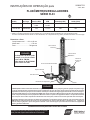
5. Attach regulator/flowmeter to cylinder valve. Align unit so
that the flowmeter tube is vertical and then tighten connection nut using a wrench.
NOTE: Inner flowtube will move downward slightly when
regulator/flowmeter is pressurized. This is normal.
6. Make sure flow control valve on regulator/flowmeter is
closed.
7. Stand so that cylinder valve is between you and regulator/
flowmeter. Open cylinder valve slowly. This will prevent
damage to gauge and critical components. When gauge
pointer stops moving, open cylinder valve fully.
NEVER stand directly in front or behind regulator/flowmeter when opening cylinder valve. ALWAYS stand so that
cylinder valve is between you and regulator/flowmeter.
NOTE: Inner flowtube will move downward slightly when
regulator/flowmeter is pressurized. This is normal.
8. Attach hose to regulator/flowmeter outlet and to downstream equipment. Tighten connection nuts with a wrench.
LEAK TESTING THE SYSTEM
1. With downstream equipment shut off (dead-ended), open
flow control valve 1/2 turn.
2. Apply Leak Test Solution such as P/N 998771 (227 gram
container) to all connections, vent holes and joints.
3. If a leak is detected anywhere in the system, it must be
corrected before operation can begin.
4. If a leak is detected in the regulator/flowmeter, it must be
removed from service and repaired.
0558007753
07/2007
Printed in U.S.A.
TO REGULATE FLOW:
Flow is controlled by adjusting flow control valve until desired flow is indicated by the ball float in the flowmeter tube.
Always take flow reading across the TOP of ball.
TO STOP WORK:
If work is to be stopped for more than a half-hour, or when
regulator/flowmeter is to be disconnected from cylinder, proceed as follows:
1. Close cylinder valve.
2. Open the flow control valve and all valves downstream to
release gas in regulator/flowmeter and hose.
3. When gauge indicates zero pressure and ball drops to
bottom of tube, close flow control valve.
NOTE: Inner flowtube will move upward when all pressure is released. This is normal.
4. Regulator/flowmeter may now be removed from cylinder.
INLET FILTER MAINTENANCE
This regulator/flowmeter is equipped with a porous metal
inlet filter, P/N 71Z33, pressed into the inlet nipple. No regulator/flowmeter should be connected to a cylinder or station
valve unless it contains this filter. The filter may be replaced
if it appears clogged. To remove filter, insert a No. 1 "EZYOUT" or a No. 6 woodscrew (about 51mm long) into filter
and pull out. Carefully press a new filter into nipple with a
6mm round metal rod.
NEVER alter relief device in any way. Blocking or tampering with relief device could cause regulator/flowmeter to
explode.
BURSTING DISC RELIEF DEVICE
A bursting disc relief device is contained in the top of the
flowtube. It is designed and intended for the protection of the
regulator/flowmeter only and not for hose or downstream
equipment. If gas escapes through relief device, immediately close cylinder valve and remove regulator/flowmeter
from service for repair. Do not use if this condition is present.
REPAIR SERVICE
If gas is escaping from relief device or a leak is detected, the
regulator/flowmeter should be returned to the nearest ESAB
distributor or to ESAB Remanufacturing Center, Ebenezer
Road, Florence, SC, 29501 for repair.
If you have your own properly equipped and staffed repair
facility, repair parts information for this regulator/flowmeter
(F-15-176) is available on request from the nearest distributor or any regional sales office.
ACCESSORY:
CO2 Heater, P/N 950578 - Recommended if CO2 regulator is
expected to operate at high flows or duty cycles. The heater
connects between regulator/flowmeter and cylinder permitting the CO2 to flow without "freezing up" the regulator/flowmeter. It requires a standard electrical extension cord with 3prong connections for 115V AC power.